JP6357178B2 - Heat exchanger and manufacturing method thereof - Google Patents
Heat exchanger and manufacturing method thereof Download PDFInfo
- Publication number
- JP6357178B2 JP6357178B2 JP2016024232A JP2016024232A JP6357178B2 JP 6357178 B2 JP6357178 B2 JP 6357178B2 JP 2016024232 A JP2016024232 A JP 2016024232A JP 2016024232 A JP2016024232 A JP 2016024232A JP 6357178 B2 JP6357178 B2 JP 6357178B2
- Authority
- JP
- Japan
- Prior art keywords
- heat
- heat transfer
- tubes
- connection
- heat exchanger
- Prior art date
- Legal status (The legal status is an assumption and is not a legal conclusion. Google has not performed a legal analysis and makes no representation as to the accuracy of the status listed.)
- Active
Links
Images


Classifications
-
- B—PERFORMING OPERATIONS; TRANSPORTING
- B23—MACHINE TOOLS; METAL-WORKING NOT OTHERWISE PROVIDED FOR
- B23K—SOLDERING OR UNSOLDERING; WELDING; CLADDING OR PLATING BY SOLDERING OR WELDING; CUTTING BY APPLYING HEAT LOCALLY, e.g. FLAME CUTTING; WORKING BY LASER BEAM
- B23K1/00—Soldering, e.g. brazing, or unsoldering
- B23K1/0008—Soldering, e.g. brazing, or unsoldering specially adapted for particular articles or work
- B23K1/0012—Brazing heat exchangers
-
- B—PERFORMING OPERATIONS; TRANSPORTING
- B23—MACHINE TOOLS; METAL-WORKING NOT OTHERWISE PROVIDED FOR
- B23K—SOLDERING OR UNSOLDERING; WELDING; CLADDING OR PLATING BY SOLDERING OR WELDING; CUTTING BY APPLYING HEAT LOCALLY, e.g. FLAME CUTTING; WORKING BY LASER BEAM
- B23K1/00—Soldering, e.g. brazing, or unsoldering
- B23K1/19—Soldering, e.g. brazing, or unsoldering taking account of the properties of the materials to be soldered
-
- B—PERFORMING OPERATIONS; TRANSPORTING
- B23—MACHINE TOOLS; METAL-WORKING NOT OTHERWISE PROVIDED FOR
- B23K—SOLDERING OR UNSOLDERING; WELDING; CLADDING OR PLATING BY SOLDERING OR WELDING; CUTTING BY APPLYING HEAT LOCALLY, e.g. FLAME CUTTING; WORKING BY LASER BEAM
- B23K1/00—Soldering, e.g. brazing, or unsoldering
- B23K1/002—Soldering by means of induction heating
-
- B—PERFORMING OPERATIONS; TRANSPORTING
- B23—MACHINE TOOLS; METAL-WORKING NOT OTHERWISE PROVIDED FOR
- B23K—SOLDERING OR UNSOLDERING; WELDING; CLADDING OR PLATING BY SOLDERING OR WELDING; CUTTING BY APPLYING HEAT LOCALLY, e.g. FLAME CUTTING; WORKING BY LASER BEAM
- B23K1/00—Soldering, e.g. brazing, or unsoldering
- B23K1/14—Soldering, e.g. brazing, or unsoldering specially adapted for soldering seams
-
- B—PERFORMING OPERATIONS; TRANSPORTING
- B23—MACHINE TOOLS; METAL-WORKING NOT OTHERWISE PROVIDED FOR
- B23K—SOLDERING OR UNSOLDERING; WELDING; CLADDING OR PLATING BY SOLDERING OR WELDING; CUTTING BY APPLYING HEAT LOCALLY, e.g. FLAME CUTTING; WORKING BY LASER BEAM
- B23K31/00—Processes relevant to this subclass, specially adapted for particular articles or purposes, but not covered by only one of the preceding main groups
- B23K31/02—Processes relevant to this subclass, specially adapted for particular articles or purposes, but not covered by only one of the preceding main groups relating to soldering or welding
-
- B—PERFORMING OPERATIONS; TRANSPORTING
- B23—MACHINE TOOLS; METAL-WORKING NOT OTHERWISE PROVIDED FOR
- B23K—SOLDERING OR UNSOLDERING; WELDING; CLADDING OR PLATING BY SOLDERING OR WELDING; CUTTING BY APPLYING HEAT LOCALLY, e.g. FLAME CUTTING; WORKING BY LASER BEAM
- B23K35/00—Rods, electrodes, materials, or media, for use in soldering, welding, or cutting
- B23K35/02—Rods, electrodes, materials, or media, for use in soldering, welding, or cutting characterised by mechanical features, e.g. shape
- B23K35/0222—Rods, electrodes, materials, or media, for use in soldering, welding, or cutting characterised by mechanical features, e.g. shape for use in soldering, brazing
-
- F—MECHANICAL ENGINEERING; LIGHTING; HEATING; WEAPONS; BLASTING
- F25—REFRIGERATION OR COOLING; COMBINED HEATING AND REFRIGERATION SYSTEMS; HEAT PUMP SYSTEMS; MANUFACTURE OR STORAGE OF ICE; LIQUEFACTION SOLIDIFICATION OF GASES
- F25B—REFRIGERATION MACHINES, PLANTS OR SYSTEMS; COMBINED HEATING AND REFRIGERATION SYSTEMS; HEAT PUMP SYSTEMS
- F25B39/00—Evaporators; Condensers
-
- F—MECHANICAL ENGINEERING; LIGHTING; HEATING; WEAPONS; BLASTING
- F28—HEAT EXCHANGE IN GENERAL
- F28D—HEAT-EXCHANGE APPARATUS, NOT PROVIDED FOR IN ANOTHER SUBCLASS, IN WHICH THE HEAT-EXCHANGE MEDIA DO NOT COME INTO DIRECT CONTACT
- F28D1/00—Heat-exchange apparatus having stationary conduit assemblies for one heat-exchange medium only, the media being in contact with different sides of the conduit wall, in which the other heat-exchange medium is a large body of fluid, e.g. domestic or motor car radiators
- F28D1/02—Heat-exchange apparatus having stationary conduit assemblies for one heat-exchange medium only, the media being in contact with different sides of the conduit wall, in which the other heat-exchange medium is a large body of fluid, e.g. domestic or motor car radiators with heat-exchange conduits immersed in the body of fluid
- F28D1/04—Heat-exchange apparatus having stationary conduit assemblies for one heat-exchange medium only, the media being in contact with different sides of the conduit wall, in which the other heat-exchange medium is a large body of fluid, e.g. domestic or motor car radiators with heat-exchange conduits immersed in the body of fluid with tubular conduits
- F28D1/047—Heat-exchange apparatus having stationary conduit assemblies for one heat-exchange medium only, the media being in contact with different sides of the conduit wall, in which the other heat-exchange medium is a large body of fluid, e.g. domestic or motor car radiators with heat-exchange conduits immersed in the body of fluid with tubular conduits the conduits being bent, e.g. in a serpentine or zig-zag
- F28D1/0477—Heat-exchange apparatus having stationary conduit assemblies for one heat-exchange medium only, the media being in contact with different sides of the conduit wall, in which the other heat-exchange medium is a large body of fluid, e.g. domestic or motor car radiators with heat-exchange conduits immersed in the body of fluid with tubular conduits the conduits being bent, e.g. in a serpentine or zig-zag the conduits being bent in a serpentine or zig-zag
-
- F—MECHANICAL ENGINEERING; LIGHTING; HEATING; WEAPONS; BLASTING
- F28—HEAT EXCHANGE IN GENERAL
- F28F—DETAILS OF HEAT-EXCHANGE AND HEAT-TRANSFER APPARATUS, OF GENERAL APPLICATION
- F28F21/00—Constructions of heat-exchange apparatus characterised by the selection of particular materials
- F28F21/08—Constructions of heat-exchange apparatus characterised by the selection of particular materials of metal
- F28F21/081—Heat exchange elements made from metals or metal alloys
- F28F21/084—Heat exchange elements made from metals or metal alloys from aluminium or aluminium alloys
-
- F—MECHANICAL ENGINEERING; LIGHTING; HEATING; WEAPONS; BLASTING
- F28—HEAT EXCHANGE IN GENERAL
- F28F—DETAILS OF HEAT-EXCHANGE AND HEAT-TRANSFER APPARATUS, OF GENERAL APPLICATION
- F28F21/00—Constructions of heat-exchange apparatus characterised by the selection of particular materials
- F28F21/08—Constructions of heat-exchange apparatus characterised by the selection of particular materials of metal
- F28F21/081—Heat exchange elements made from metals or metal alloys
- F28F21/085—Heat exchange elements made from metals or metal alloys from copper or copper alloys
-
- F—MECHANICAL ENGINEERING; LIGHTING; HEATING; WEAPONS; BLASTING
- F28—HEAT EXCHANGE IN GENERAL
- F28F—DETAILS OF HEAT-EXCHANGE AND HEAT-TRANSFER APPARATUS, OF GENERAL APPLICATION
- F28F9/00—Casings; Header boxes; Auxiliary supports for elements; Auxiliary members within casings
- F28F9/26—Arrangements for connecting different sections of heat-exchange elements, e.g. of radiators
-
- B—PERFORMING OPERATIONS; TRANSPORTING
- B23—MACHINE TOOLS; METAL-WORKING NOT OTHERWISE PROVIDED FOR
- B23K—SOLDERING OR UNSOLDERING; WELDING; CLADDING OR PLATING BY SOLDERING OR WELDING; CUTTING BY APPLYING HEAT LOCALLY, e.g. FLAME CUTTING; WORKING BY LASER BEAM
- B23K2101/00—Articles made by soldering, welding or cutting
- B23K2101/04—Tubular or hollow articles
- B23K2101/06—Tubes
-
- B—PERFORMING OPERATIONS; TRANSPORTING
- B23—MACHINE TOOLS; METAL-WORKING NOT OTHERWISE PROVIDED FOR
- B23K—SOLDERING OR UNSOLDERING; WELDING; CLADDING OR PLATING BY SOLDERING OR WELDING; CUTTING BY APPLYING HEAT LOCALLY, e.g. FLAME CUTTING; WORKING BY LASER BEAM
- B23K2101/00—Articles made by soldering, welding or cutting
- B23K2101/04—Tubular or hollow articles
- B23K2101/14—Heat exchangers
-
- B—PERFORMING OPERATIONS; TRANSPORTING
- B23—MACHINE TOOLS; METAL-WORKING NOT OTHERWISE PROVIDED FOR
- B23K—SOLDERING OR UNSOLDERING; WELDING; CLADDING OR PLATING BY SOLDERING OR WELDING; CUTTING BY APPLYING HEAT LOCALLY, e.g. FLAME CUTTING; WORKING BY LASER BEAM
- B23K2103/00—Materials to be soldered, welded or cut
- B23K2103/08—Non-ferrous metals or alloys
- B23K2103/10—Aluminium or alloys thereof
-
- B—PERFORMING OPERATIONS; TRANSPORTING
- B23—MACHINE TOOLS; METAL-WORKING NOT OTHERWISE PROVIDED FOR
- B23K—SOLDERING OR UNSOLDERING; WELDING; CLADDING OR PLATING BY SOLDERING OR WELDING; CUTTING BY APPLYING HEAT LOCALLY, e.g. FLAME CUTTING; WORKING BY LASER BEAM
- B23K2103/00—Materials to be soldered, welded or cut
- B23K2103/08—Non-ferrous metals or alloys
- B23K2103/12—Copper or alloys thereof
-
- F—MECHANICAL ENGINEERING; LIGHTING; HEATING; WEAPONS; BLASTING
- F28—HEAT EXCHANGE IN GENERAL
- F28F—DETAILS OF HEAT-EXCHANGE AND HEAT-TRANSFER APPARATUS, OF GENERAL APPLICATION
- F28F2275/00—Fastening; Joining
- F28F2275/04—Fastening; Joining by brazing
-
- F—MECHANICAL ENGINEERING; LIGHTING; HEATING; WEAPONS; BLASTING
- F28—HEAT EXCHANGE IN GENERAL
- F28F—DETAILS OF HEAT-EXCHANGE AND HEAT-TRANSFER APPARATUS, OF GENERAL APPLICATION
- F28F2275/00—Fastening; Joining
- F28F2275/04—Fastening; Joining by brazing
- F28F2275/045—Fastening; Joining by brazing with particular processing steps, e.g. by allowing displacement of parts during brazing or by using a reservoir for storing brazing material
Landscapes
- Engineering & Computer Science (AREA)
- Mechanical Engineering (AREA)
- Physics & Mathematics (AREA)
- Thermal Sciences (AREA)
- General Engineering & Computer Science (AREA)
- Chemical & Material Sciences (AREA)
- Materials Engineering (AREA)
- Heat-Exchange Devices With Radiators And Conduit Assemblies (AREA)
- Details Of Heat-Exchange And Heat-Transfer (AREA)
Description
本発明は、伝熱管と接続管とがろう付け接合された熱交換器、およびその製造方法に関する。 The present invention relates to a heat exchanger in which a heat transfer tube and a connection tube are brazed and joined, and a method for manufacturing the same.
従来、クロスフィンチューブ熱交換器は銅製の伝熱管で構成され、伝熱管はラインバーナ設備等を用いリン銅ろうで部分的にろう付されていた。近年は材料費低減のために、伝熱管にアルミ管を用い始めており、Al−Siろうを用いてろう付されているが、アルミ管の場合は母材とろう材の融点が近いために、母材を溶融させずにろう付することが難しい。 Conventionally, the cross fin tube heat exchanger is composed of a copper heat transfer tube, and the heat transfer tube is partially brazed with phosphorous copper brazing using a line burner facility or the like. In recent years, in order to reduce material costs, aluminum tubes have begun to be used for heat transfer tubes, and brazing has been performed using Al-Si brazing, but in the case of aluminum tubes, the melting point of the base material and brazing material is close, It is difficult to braze the base material without melting it.
また、クロスフィンチューブ熱交換器では様々な形状の接続管が用いられるので、例えばラインバーナで均一に加熱したとしても、各接続管の熱容量が互いに異なっていたり、各接続管に対するバーナの火炎の当たり方が互いに異なるのでろう付部温度がバラツキを持つ。 In addition, the cross fin tube heat exchanger uses connecting pipes of various shapes. For example, even when heated uniformly by a line burner, the heat capacities of the connecting pipes differ from one another, Since the ways of contact are different, the brazing part temperature varies.
アルミ製の熱交換器をラインバーナ等でろう付する際には、この温度バラツキのために容易にろう付ができないことが大きな問題になる。 When brazing an aluminum heat exchanger with a line burner or the like, a major problem is that brazing cannot be easily performed due to this temperature variation.
特に、伝熱管が熱交換器の奥行き方向に3列以上配置されている場合、中央列の伝熱管では火炎の当たり方が両端の列の伝熱管に比べて弱くなるため、ろう付部温度のバラツキが顕著になる。 In particular, when the heat transfer tubes are arranged in three or more rows in the depth direction of the heat exchanger, the flame contact is weaker in the central heat transfer tubes than in the heat transfer tubes in both ends. The variation becomes remarkable.
そのため、特許文献1では、ZnまたはZn−Alの様な低融点ろうを用いる方法が提案されている。 Therefore, Patent Document 1 proposes a method using a low melting point solder such as Zn or Zn—Al.
特許文献1の従来技術では、ろう材の電位が母材よりも大幅に低く優先腐食するので、ろう付部を被覆する必要がある。具体的には、被覆材として、熱収縮チューブや塗料が用いられている。 In the prior art of Patent Document 1, the potential of the brazing material is significantly lower than that of the base metal and preferential corrosion occurs, so that it is necessary to cover the brazing portion. Specifically, a heat-shrinkable tube or paint is used as the covering material.
上記特許文献1の従来技術において、被覆材としてろう付部に塗料を塗る方法は、ろう付後のフラックス残渣を事前に除去する工程が必要なため、大幅に工数が増える問題がある。 In the prior art of Patent Document 1 described above, the method of applying a paint to a brazing part as a coating material has a problem that the number of man-hours is significantly increased because a step of removing the flux residue after brazing is required in advance.
また、被覆材として熱収縮チューブを用いる方法は、Uベンド形状の接続管に対してはろう付け後の接続管の被覆には用いることができず、適用は限定的である。 In addition, the method using a heat shrinkable tube as a covering material cannot be used for covering a connection pipe after brazing for a U-bend connection pipe, and its application is limited.
本発明は上記点に鑑みて、伝熱管と接続管とのろう付け接合品質が高い熱交換器、およびその製造方法を提供することを目的とする。 An object of this invention is to provide the heat exchanger with the high brazing joining quality of a heat exchanger tube and a connection pipe, and its manufacturing method in view of the said point.
上記目的を達成するため、請求項1に記載の発明では、
熱媒体が流れ、互いに並んで配置された複数のアルミニウム製の伝熱管(11)と、
熱媒体が流れ、伝熱管(11)の端部にろう付け接合された複数のアルミニウム製の接続管(12、13)と、
複数の接続管(12、13)のうち少なくとも2つの接続管(12、13)の少なくとも一部に熱伝導可能に接触するように配置され、熱伝導体で形成された均熱化手段(21、22)とを備え、
均熱化手段(21、22)および複数の接続管(12、13)は互いにろう付け接合されており、
複数の伝熱管(11)と複数の接続管(12、13)とを接合しているろう材は、均熱化手段(21、22)と複数の接続管(12、13)とを接合しているろう材よりも低融点であることを特徴とする。
In order to achieve the above object, in the invention described in claim 1,
A plurality of aluminum heat transfer tubes (11) arranged such that the heat medium flows and is arranged side by side;
A plurality of aluminum connecting tubes (12, 13) in which the heat medium flows and brazed to the end of the heat transfer tube (11);
Heat equalizing means (21) formed of a heat conductor, arranged so as to contact at least part of at least two of the plurality of connection pipes (12, 13) so as to be capable of conducting heat. 22) ,
The soaking means (21, 22) and the plurality of connecting pipes (12, 13) are brazed to each other,
The brazing material joining the plurality of heat transfer tubes (11) and the plurality of connection tubes (12, 13) joins the heat equalizing means (21, 22) and the plurality of connection tubes (12, 13). wherein the low-melting der Rukoto than the brazing material is.
これによると、熱交換器の製造工程において伝熱管(11)と接続管(12、13)とを加熱によってろう付けする際に、接続管(12、13)同士が均熱化手段(21、22)を介して熱伝導するので、接続管(12、13)相互間で昇温にバラツキが生じることを抑制できる。 According to this, when brazing the heat transfer tubes (11) and the connection tubes (12, 13) by heating in the manufacturing process of the heat exchanger, the connection tubes (12, 13) are connected to the temperature-equalizing means (21, 22) Since heat conduction is performed via 22), it is possible to suppress variations in temperature rise between the connecting pipes (12, 13).
そのため、各接続管(12、13)から接合部(16)への熱伝導バラツキを抑制できるので、伝熱管(11)と接続管(12、13)とのろう付けを均熱化できる。したがって、伝熱管(11)と接続管(12、13)とのろう付け接合品質が高い熱交換器を提供できる。 Therefore, variation in heat conduction from each connecting pipe (12, 13) to the joint (16) can be suppressed, so that the brazing between the heat transfer pipe (11) and the connecting pipe (12, 13) can be equalized. Therefore, a heat exchanger with high brazing joint quality between the heat transfer tube (11) and the connection tubes (12, 13) can be provided.
上記目的を達成するため、請求項5に記載の発明では、
熱媒体が流れ、互いに並んで配置されたアルミニウム製の複数の伝熱管(11)と、
熱媒体が流れ、複数の伝熱管(11)の端部に接合されたアルミニウム製の複数の接続管(12、13)とを備える熱交換器の製造方法であって、
複数の接続管(12、13)のうち少なくとも2つの接続管(12、13)の少なくとも一部に、熱伝導体で形成された均熱化手段(21、22)を熱伝導可能に接触するように配置し、且つ均熱化手段(21、22)および複数の接続管(12、13)を互いにろう付け接合した状態で、複数の伝熱管(11)と複数の接続管(12、13)とをろう付け接合することを含み、
複数の伝熱管(11)と複数の接続管(12、13)とを接合するろう材として、均熱化手段(21、22)と複数の接続管(12、13)とを接合するろう材よりも低融点であるものを用いることを特徴とする。
In order to achieve the above object, in the invention described in claim 5 ,
A plurality of aluminum heat transfer tubes (11) arranged such that the heat medium flows and is arranged side by side;
A heat exchanger flows, and a method of manufacturing a heat exchanger comprising a plurality of aluminum connection pipes (12, 13) joined to ends of a plurality of heat transfer pipes (11),
A temperature-equalizing means (21, 22) formed of a heat conductor is brought into contact with at least a part of at least two of the plurality of connection pipes (12, 13) so as to conduct heat. And the heat equalizing means (21, 22) and the plurality of connecting pipes (12, 13) are brazed and joined to each other , and the plurality of heat transfer pipes (11) and the plurality of connecting pipes (12, 13) and only contains that brazing,
As a brazing material for joining the plurality of heat transfer tubes (11) and the plurality of connection tubes (12, 13), a brazing material for joining the heat equalizing means (21, 22) and the plurality of connection tubes (12, 13). What has a lower melting point than that is used .
これによると、上記した請求項1に記載の発明と同様の作用効果を奏することができる。
なお、この欄および特許請求の範囲で記載した各手段の括弧内の符号は、後述する実施形態に記載の具体的手段との対応関係を示すものである。
According to this, there can exist an effect similar to invention of Claim 1 mentioned above.
In addition, the code | symbol in the bracket | parenthesis of each means described in this column and the claim shows the correspondence with the specific means as described in embodiment mentioned later.
以下、実施形態について図に基づいて説明する。以下の各実施形態相互において、互いに同一もしくは均等である部分には、図中、同一符号を付してある。 Hereinafter, embodiments will be described with reference to the drawings. In the following embodiments, the same or equivalent parts are denoted by the same reference numerals in the drawings.
(第1実施形態)
まず、ろう付け接合によって製造された熱交換器10を図1〜図4に基づいて説明する。熱交換器10は、冷凍サイクルの冷媒と、空気とを熱交換させる冷凍サイクル用熱交換器である。
(First embodiment)
First, the
図中、矢印Wは、熱交換器10の幅方向を示している。図中、矢印Dは、熱交換器10の奥行き方向を示している。図中、矢印Hは、熱交換器10の高さ方向を示している。
In the drawing, an arrow W indicates the width direction of the
熱交換器10は、多数本の伝熱管11と、多数本の接続管12、13と、多数枚のフィン14と、サイドプレート17とを備えている。熱交換器10は、多数本の管状の伝熱管11が多数枚の板状のフィン14に差し込まれたクロスフィンチューブ型熱交換器である。
The
伝熱管11は、その内部を流れる冷媒と、伝熱管11の外部を流れる空気とを熱交換させる熱交換部材である。伝熱管11は、熱交換器10の高さ方向Hに直線状に延びている。多数本の伝熱管11は、熱交換器10の幅方向Wに並んで配置されている。すなわち、伝熱管11の並び方向は、熱交換器10の幅方向Wと一致している。
The
伝熱管11は、熱交換器10の奥行き方向Dにも複数列、配置されている。伝熱管11の外部を流れる空気は、熱交換器10の奥行き方向Dに流れる。
The
多数本の接続管12、13はチューブ用接続管12とタンク用接続管13とに大別される。チューブ用接続管12は、ヘアピン状に屈曲した形状を有しており、2本の伝熱管11の一端部同士を接続させている。
The multiple connecting
タンク用接続管13は、略直線状に延びた形状を有しており、図2に示すように、伝熱管11の一端部を冷媒タンク15に接続させている。冷媒タンク15は、複数本の伝熱管11に冷媒を分配する分配タンク、または複数本の伝熱管11からの冷媒が集合する集合タンクである。
The
多数枚のフィン14は、伝熱管11と空気との伝熱面積を増大させて空気と冷媒との熱交換を促進する伝熱促進部材である。フィン14は、板状に形成されたプレートフィンである。伝熱管11およびフィン14は、冷媒と空気とを熱交換させるコア部18を構成している。
The
多数枚のフィン14は、熱交換器10の高さ方向H(換言すれば伝熱管11の長手方向)に互いに積層されている。多数枚のフィン14には、多数本の伝熱管11が串刺し状に貫通している。伝熱管11は機械拡管されていてフィン14と密着している。
The
伝熱管11およびフィン14は、熱交換器10のコア部18を構成している。サイドプレート17は、コア部18を補強する補強部材である。
The
伝熱管11、接続管12、13、フィン14およびサイドプレート17の材質は、アルミニウム合金である。伝熱管11が拡管されることによって、伝熱管11、フィン14およびサイドプレート17が密着接合される。ろう材が加熱されて溶かされることによって、伝熱管11および接続管12、13がろう付け接合される。
The material of the
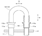
図3に示すように伝熱管11の端部には口拡部11aおよびフレア部11bが形成されている。口拡部11aは、伝熱管11の端部開口部が拡径されることによって形成されている。フレア部11bは、口拡部11aがさらにフレア加工されることによって形成されている。伝熱管11の口拡部11aには、接続管12、13の先端が挿入されている。伝熱管11と接続管12、13の嵌合隙間がろう付け接合されることによって、冷媒流路が形成されている。
As shown in FIG. 3, an
伝熱管11と接続管12、13との接合部16は、熱交換器10の幅方向Wに多数個並んでいる。接合部16は、熱交換器10の奥行き方向Dにも複数列、配置されている。これらの接合部16は、熱交換器10の高さ方向Hにおける位置が互いに同じになっている。
A large number of
図4に示すように、チューブ用接続管12は、熱交換器10の幅方向Wに対して平行に配置された短尺の接続管12Aと、熱交換器10の幅方向Wに対して斜めに配置された短尺の接続管12Bと、長尺の接続管12Cとが混在している。タンク用接続管13は、冷媒の出入口配管である。
As shown in FIG. 4, the
次に、熱交換器10の製造方法を説明する。まず、各フィン14およびサイドプレート17に伝熱管11が挿通される図示しない貫通孔を形成する。そして、各フィン14を互いに等間隔に配置した後、貫通孔に伝熱管11を挿通する。
Next, a method for manufacturing the
この後、伝熱管10を拡管する拡管工程を行う。具体的には、伝熱管11の内径よりも径が大きい図示しない拡管子を伝熱管11内に挿通し、拡管子により伝熱管11を機械的に拡管する。伝熱管11を拡管することで、各フィン14およびサイドプレート17と伝熱管11とを密着させて接合する。この後、伝熱管11の端部に口拡部11aおよびフレア部11bを形成する。これにより、図5に示すように、熱交換器10のコア部18が製造される。
Then, the pipe expansion process which expands the
また、接続管12、13に均熱部材21を組み付ける組付工程を行う。例えば、接続管12、13と均熱部材21とをAl−Si系のろう材でろう付け接合する。接続管12、13と均熱部材21とを溶接、カシメ等によって固定してもよい。これにより、図6に示すように、接続管12、13と均熱部材21とを有する接続管組付体19が製造される。
Further, an assembling step for assembling the
接続管12、13のうち図3中で波線を付した部位、すなわち接続管12、13との接合予定部16の近傍部位には、弗化セシウム系を含む非腐食性フラックスとAl−Cu−Si三元素系共晶組成近傍のろう材、またはその成分にZnを添加したAl−Cu−Si−Zn系のろう材を適宜塗布する。
In the connecting
Al−Cu−Si系のろう材は、固相線温度510℃、液相線温度540℃程度に成分調整されており、Al−Si系の固相線温度577℃に対して大幅に低温化されている。この温度域でろう付するためにフラックスは420℃の低温から活性を有する。 The Al—Cu—Si brazing material is adjusted to have a solidus temperature of about 510 ° C. and a liquidus temperature of about 540 ° C., which is significantly lower than the Al—Si based solidus temperature of 577 ° C. Has been. In order to braze in this temperature range, the flux is active from a low temperature of 420 ° C.
均熱部材21は、伝熱管11と接続管12、13とのろう付けを均熱化する均熱化手段である。均熱部材21は、例えばアルミニウムで形成されている。
The soaking
拡管工程および組付工程の後、加熱接合工程を行う。加熱接合工程では、コア部18の伝熱管11に接続管組付体19の接続管12、13を加熱によって接合する。具体的には、図7、図8、図9に示すように、伝熱管11に接続管12、13を仮組み付けした後、伝熱管11と接続管12、13との接合予定部16をラインバーナ30によって局部加熱する。ラインバーナ30は、接合予定部16を、熱交換器10の奥行き方向Dの外側から加熱する。
After the tube expansion process and the assembly process, a heat bonding process is performed. In the heat joining step, the connecting
これにより、伝熱管11と接続管12、13との接合予定部16が550℃程度に局部加熱されるので、接続管12、13のうち図3中で波線を付した部位、すなわち接合予定部16の近傍部位に塗布されたろう材が溶融されて伝熱管11のフレア部11bを介して伝熱管11と接続管12、13の嵌合隙間に流れ込むので、伝熱管11と接続管12、13とがろう付け接合される。
Thereby, since the joining
本実施形態では、接続管12、13の形状が互いに異なっているので、接続管12、13の熱容量も互いに異なっている。そのため、均熱部材21が設けられていない場合、各ろう付け部(換言すれば、伝熱管11と接続管12、13の嵌合部)の温度が不均一となり、ろう廻り不足や母材溶融が発生する。
In this embodiment, since the shapes of the connecting
この点、本実施形態では、均熱部材21が設けられているので、接続管12、13の形状および熱容量が互いに異なっていても、均熱部材21の熱伝導の効果でろう付け部の温度バラツキを大幅に低減できるので、母材の溶融やろうの溶融不足を生じさせることなく、多数のろう付け部をラインバーナ30でろう付することができる。
In this respect, in the present embodiment, since the
すなわち、接続管12、13同士が均熱部材21を介して熱伝導するので、接続管12、13相互間の昇温バラツキが抑制される。そのため、伝熱管11と接続管12、13とのろう付けが均熱化されるので、ろう付け品質が高くなる。
That is, since the connecting
また、接続管12、13と伝熱管11とのろう付けにAl−Cu−Si三元素系共晶組成近傍の低融点ろう材、または、その成分にZnを添加したAl−Cu−Si−Zn系の低融点ろう材を用いているので、アルミ母材とろう材との融点差が拡大して、ろう付が容易になる。
In addition, a low melting point brazing material in the vicinity of an Al—Cu—Si three-element eutectic composition for brazing between the connecting
ろう材の組成を適切に選定することによってアルミ母材との自然電位差を小さくできるので、ろう材が優先腐食することを防止できる。 By appropriately selecting the composition of the brazing material, the natural potential difference with the aluminum base material can be reduced, so that the preferential corrosion of the brazing material can be prevented.
さらに、均熱部材21と接続管12、13とを高融点のAl−Si系のろう材で接合しているので、接続管12、13と伝熱管11とを低融点ろう材でろう付する際に二次溶解することを抑制できる。
Furthermore, since the
図10に示す変形例では、伝熱管11が熱交換器10の奥行き方向Dにも3列以上配置されている。この変形例では、熱交換器10の奥行き方向Dにおける中央列の伝熱管11では火炎の当たり方が両端の列の伝熱管11に比べて弱くなるが、均熱部材21による伝熱の効果、およびAl−Cu−Siの三元素系ろう材の採用によるろう付温度範囲の拡大の効果で、3列以上の全ての列を同時にラインバーナろう付することが容易になる。
In the modification shown in FIG. 10, the
本実施形態では、接続管12、13と伝熱管11とのろう付けにAl−Cu−Siの三元素系を用いているが、接続管12、13の形状差が小さい場合には、Al−Si系ろう材を用いてもよい。
In the present embodiment, a three-element system of Al—Cu—Si is used for brazing the
本実施形態では、均熱部材21は、熱伝導体で形成されており、複数の接続管12、13のうち少なくとも2つの接続管12、13の少なくとも一部に熱伝導可能に接触するように配置されている。
In the present embodiment, the
これによると、熱交換器の製造工程において伝熱管11と接続管12、13とを加熱によってろう付けする際に、接続管12、13同士が均熱部材21を介して熱伝導するので、接続管12、13相互間で昇温にバラツキが生じることを抑制できる。
According to this, when the
そのため、各接続管12、13から接合部16への熱伝導バラツキを抑制できるので、伝熱管11と接続管12、13とのろう付けを均熱化できる。したがって、伝熱管11と接続管12、13とのろう付け接合品質が高い熱交換器を提供できる。
Therefore, variation in heat conduction from the
図10のように複数の伝熱管11が3列以上配置されている熱交換器においても伝熱管11と接続管12、13とのろう付けを均熱化して、高いろう付け接合品質を得ることができる。
Even in a heat exchanger in which a plurality of
本実施形態では、均熱部材21および複数の接続管12、13は互いにろう付け接合されている。複数の伝熱管11と複数の接続管12、13とを接合しているろう材は、均熱部材21と複数の接続管12、13とを接合しているろう材よりも低融点である。
In the present embodiment, the
これにより、接続管12、13と伝熱管11とをろう付接合する際に、均熱部材21と複数の接続管12、13とを接合しているろう材が二次溶解することを抑制できる。
Thereby, when the
本実施形態では、複数の伝熱管11と複数の接続管12、13とを接合しているろう材は、Al−Cu−Si系またはAl−Cu−Si−Zn系である。これによると、複数の伝熱管11と複数の接続管12、13とを接合しているろう材の融点が低いので、アルミニウム製の伝熱管11および接続管12、13とろう材との融点差が拡大する。そのため、伝熱管11と接続管12、13とのろう付が容易である。
In the present embodiment, the brazing material joining the plurality of
本実施形態では、均熱部材21および複数の接続管12、13は、互いに機械的に接触している。これにより、接続管12、13と伝熱管11とを低融点ろう材でろう付する際に均熱部材21と複数の接続管12、13とを確実に接触させて確実に熱伝導させることができる。
In the present embodiment, the
本実施形態では、複数の接続管12、13のうち少なくとも2つの接続管12、13の少なくとも一部に、熱伝導体で形成された均熱部材21を熱伝導可能に接触するように配置した状態で、複数の伝熱管11と複数の接続管12、13とをろう付け接合する。
In the present embodiment, a
これによると、熱交換器の製造工程において伝熱管11と接続管12、13とを加熱によってろう付けする際に、接続管12、13同士が均熱部材21を介して熱伝導するので、接続管12、13相互間で昇温にバラツキが生じることを抑制できる。
According to this, when the
そのため、各接続管12、13から接合部16への熱伝導バラツキを抑制できるので、伝熱管11と接続管12、13とのろう付けを均熱化できる。したがって、伝熱管と接続管とのろう付け接合品質が高い熱交換器の製造方法を提供できる。
Therefore, variation in heat conduction from the
本実施形態では、フィン14と複数の伝熱管11とを組み付けてコア部18を製造し、均熱部材21と複数の接続管12、13とを組み付けて接続管組付体19を製造し、コア部18と接続管組付体19とを組み付けて複数の伝熱管11と複数の接続管12、13とをろう付け接合する。
In this embodiment, the
これにより、複数の伝熱管11と複数の接続管12、13とをろう付け接合する際に、複数の接続管12、13に均熱部材21を熱伝導可能に確実に接触させることができる。
Accordingly, when the plurality of
(第2実施形態)
上記実施形態では、伝熱管11に接続管12、13をバーナ加熱によって接合するが、本実施形態では、伝熱管11に接続管12、13を高周波誘導加熱によって接合する。
(Second Embodiment)
In the said embodiment, although the
具体的には、上記実施形態と同様に拡管工程を行って熱交換器10のコア部18を形成するとともに組付工程を行って接続管組付体19を形成した後、高周波誘導加熱工程を行う。
Specifically, the tube expansion process is performed to form the
高周波誘導加熱工程では、伝熱管11と接続管12、13との接合予定部16を高周波誘導加熱によって局部加熱する。これにより、伝熱管11と接続管12、13とがろう付け接合される。
In the high frequency induction heating process, the
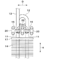
高周波誘導加熱工程の詳細を説明する。まず、図11、図12に示すように、接合予定部16の側方に高周波誘導加熱用のコイル20を配置するとともに、コイル20の上方に均熱部材21を配置する。
Details of the high-frequency induction heating process will be described. First, as shown in FIGS. 11 and 12, the
コイル20の配置の仕方の例を図13に示す。図13(a)の例では、コイル20を、伝熱管11の両側方および伝熱管11同士の間に、熱交換器10の幅方向W(図13(a))の紙面垂直方向)に差し込む。
An example of how to arrange the
図13(b)〜(d)の例のように、図13(a)の例に対してコイル20を挿入しない箇所があってもよい。
Like the example of FIG.13 (b)-(d), there may be a location which does not insert the
均熱部材21は、伝熱管11と接続管12、13とのろう付けを均熱化する均熱化手段である。均熱部材21は、磁束の通過を抑制する磁性体である。均熱部材21は、熱伝導体で形成された熱伝導部材である。均熱部材21は、例えばアルミニウムで形成されている。
The soaking
均熱部材21を、接続管12、13のうち接合予定部16から最も離れた部位とコイル20との間に、ろう付け、溶接または治具を用いて仮固定する。均熱部材21を、高周波誘導加熱工程の前に予め仮固定しておいてもよい。
The
均熱部材21は、熱交換器10の幅方向Wに延びる板状の部材である。均熱部材21には、接続管12、13が貫通する孔21aが形成されている。均熱部材21のうち孔21aの周縁部は、接続管12、13の外周面に接触している。
The soaking
コイル20および均熱部材21を上記位置に配置した状態でコイル20に電流を流す。これにより発生する磁束によって、接合予定部16が高周波誘導加熱されてろう材が溶ける。
A current is passed through the
このとき、均熱部材21によって、磁束による昇温バラツキを抑制することができる。その理由を以下に説明する。
At this time, the temperature-uniforming
高周波誘導加熱では、磁束密度が高い部位が多く加熱される。そのため、均熱部材21を用いない場合、磁束密度および熱容量によって全体の温度が決まる。磁束密度は、コイル20の位置と、磁束が触れる配管との距離によって決まる。
In high frequency induction heating, many parts with high magnetic flux density are heated. Therefore, when the soaking
各接続管12、13がUベント高さ違いやL字曲げの部位違い等のように互いに異なる形状になっていたり、各接続管12、13の設置向きが互いに異なっていたりすると、各接続管12、13とコイル20との距離が互いに異なることとなるため、各接続管12、13の熱容量が互いに同じでも接続管12、13相互間で昇温バラツキが発生し、ろう付部相互間の温度バラツキが大きくなってしまう。
If the connecting
この点、本実施形態では、磁性体である均熱部材21のシールド効果により、磁束の通過が抑制される。そのため、接続管12、13のうちコイル20に対して均熱部材21よりも離れた部位の形状が互いに異なっていても、接続管12、13のうちコイル20に対して均熱部材21よりも近い部位の形状とコイル20からの位置とが均一であれば、磁束による昇温バラツキを抑制することができる。
In this regard, in the present embodiment, the passage of magnetic flux is suppressed by the shielding effect of the
さらに、接続管12、13同士が均熱部材21を介して熱伝導するので、接続管12、13相互間の昇温バラツキが一層抑制される。そのため、伝熱管11と接続管12、13とのろう付けが一層均熱化されるので、ろう付け品質が一層高くなる。
Furthermore, since the connecting
図14の二点鎖線に示すように、均熱部材21を用いない比較例では各接合予定部16の温度バラツキが約140℃である。これに対し、図14の実線に示すように、均熱部材21を用いる本実施形態では、各接合予定部16の温度バラツキが約45℃になり、比較例に対して温度バラツキが約100℃も低減される。
As shown by the two-dot chain line in FIG. 14, in the comparative example in which the soaking
本実施形態では、均熱部材21は、高周波誘導加熱によって接続管12、13にろう付けされる。すなわち、本実施形態では、均熱部材21は、熱交換器10の構成部品である。
In the present embodiment, the
均熱部材21を、高周波誘導加熱後、接続管12、13から取り外すようにしてもよい。すなわち、均熱部材21は、熱交換器10の製造工程で用いられる治具であってもよい。
The soaking
本実施形態では、コイル20を接合予定部16の側方に配置するとともに、均熱部材21、22を接続管12、13のうち接合予定部16から最も離れた部位とコイル20との間に配置した状態で、コイル20に電流を流すことによって、伝熱管11と接続管12、13とを接合予定部16で高周波誘導加熱によってろう付けする。
In this embodiment, while arrange | positioning the
これによると、高周波誘導加熱時に均熱部材21、22が磁束の通過を抑制することによって、接続管12、13のうちコイル20に対して均熱部材21よりも離れた部位の磁束密度を低下させて当該部位の昇温を抑制できる。そのため、接続管12、13毎に形状が違っても接続管12、13相互間で昇温にバラツキが生じることを抑制できる。
According to this, when the soaking
したがって、各接続管12、13から各接合予定部16への熱伝導バラツキを抑制できるので、伝熱管11と接続管12、13とのろう付けを均熱化でき、ひいては熱交換器10における伝熱管11と接続管12、13とのろう付け接合品質を高くできる。
Therefore, variation in heat conduction from each connecting
本実施形態では、均熱部材21、22を、接続管12、13の少なくとも一部に熱伝導可能に接触させる。
In the present embodiment, the
これにより、接続管12、13同士が均熱部材21を介して熱伝導するので、接続管12、13相互間の昇温バラツキを一層抑制できる。そのため、伝熱管11と接続管12、13とのろう付けを一層均熱化できるので、伝熱管11と接続管12、13とのろう付け品質を一層高くできる。
Thereby, since the
本実施形態では、均熱部材21、22として、伝熱管11の並び方向Wに延びる部材を用いる。これにより、一度の高周波誘導加熱によって、多数の接合予定部16をろう付け接合できる。
In the present embodiment, as the soaking
(第3実施形態)
上記実施形態では、均熱部材21は、伝熱管11の並び方向Wに延びる板状の部材であるが、本実施形態では、図15、図16に示すように、均熱部材22は、伝熱管11同士の間に嵌まり込むブロック状の部材である。
(Third embodiment)
In the above embodiment, the
均熱部材22は、磁束を集中させて磁束の通過を抑制する磁性体である。磁束通過抑制部材22は、例えばアルミニウムで形成されている。
The
均熱部材22を、接続管12、13のうち接合予定部16から最も離れた部位とコイル20との間に、ろう付け、溶接または治具を用いて仮固定する。均熱部材21を、高周波誘導加熱工程の前に予め仮固定しておいてもよい。均熱部材22の縁部は、接続管12、13の外周面に接触している。
The
本実施形態のように、均熱部材22として、伝熱管11同士の間に嵌まり込む部材を用いても、上記実施形態と同様の作用効果を奏することができる。
Even if a member that fits between the
(第4実施形態)
本実施形態では、図17に示すように、板状の均熱部材21の端部が延長され且つコイル20と逆方向に曲げられている。これにより、均熱部材21の端部への磁束集中を低減できるとともに均熱部材21の端部の熱容量を増加できるので、伝熱管11と接続管12、13とのろう付けを一層均熱化できる。
(Fourth embodiment)
In the present embodiment, as shown in FIG. 17, the end of the plate-shaped
(第5実施形態)
本実施形態では、図18に示すように、板状の均熱部材21が、両端列の伝熱管11の近傍には設けられず、中央列の伝熱管11の近傍のみに設けられる。
(Fifth embodiment)
In the present embodiment, as shown in FIG. 18, the plate-shaped
これによると、中央列の伝熱管11の近傍に設けられた均熱部材21が誘導加熱されて発熱するので、発熱量の少ない中央列の伝熱管11を、発熱量の多い両端列の伝熱管11と同程度の温度にすることができる。その結果、伝熱管11と接続管12、13とのろう付けを一層均熱化できる。
According to this, since the
(第6実施形態)
本実施形態では、図19に示すように、板状の均熱部材21が屈曲した形状を有しており、均熱部材21の中央側の部位が両端側の部位と比較してコイル20の近くに位置している。
(Sixth embodiment)
In this embodiment, as shown in FIG. 19, the plate-shaped
均熱部材21のうち中央側の部位では両端側の部位と比較して磁束密度が高くなって発熱量が多くなるので、発熱量の少ない中央列の伝熱管11への伝熱量が多くなる。これにより、発熱量の少ない中央列の伝熱管11を、発熱量の多い両端列の伝熱管11と同程度の温度にすることができるので、伝熱管11と接続管12、13とのろう付けを一層均熱化できる。
Since the magnetic flux density is higher in the central part of the
(第7実施形態)
本実施形態では、図20に示すように、サイドプレート17の両端が接続管12、13側に曲げられている。製造上の誤差等の理由により、サイドプレート17の組み付け位置にバラツキが生じるので、最短列の伝熱管11とサイドプレート17の曲げ部との間の距離にもバラツキが生じる。最短列の伝熱管11とサイドプレート17の曲げ部との間の距離が長いと最端列の伝熱管11では磁束密度が高くなるので高温になる。
(Seventh embodiment)
In the present embodiment, as shown in FIG. 20, both ends of the
そこで、本実施形態では、均熱部材21の端部が、サイドプレート17の曲げ位置とコイル20との間に曲げられた形状になっている。これにより、均熱部材21の曲げ部が誘導加熱されるので、サイドプレート17の影響を排除でき、安定した均熱性が得られる。
Therefore, in the present embodiment, the end portion of the soaking
(第8実施形態)
本実施形態では、伝熱管11の肉厚が互いに異なっている。図21の例では、右方側の2本の伝熱管11の肉厚が、左方側の2本の伝熱管11の肉厚よりも薄くなっている。
(Eighth embodiment)
In the present embodiment, the
板状の均熱部材21は屈曲した形状を有しており、均熱部材21のうち薄肉の伝熱管11側の部位は、厚肉の伝熱管11側の部位と比較してコイル20から離されている。
The plate-shaped
均熱部材21のうち薄肉の伝熱管11側の部位は、厚肉の伝熱管11側の部位と比較して磁束密度が小さくなって発熱量が少なくなる。そのため、熱容量の小さい薄肉の伝熱管11と、熱容量の大きい厚肉の伝熱管11とで温度を均一化できるので、伝熱管11と接続管12、13とのろう付けを一層均熱化できる。
The part of the
(第9実施形態)
本実施形態では、伝熱管11の肉厚が互いに異なっている。図22の例では、右方側の2本の伝熱管11の肉厚が、左方側の2本の伝熱管11の肉厚よりも薄くなっている。
(Ninth embodiment)
In the present embodiment, the
板状の均熱部材21のうち薄肉の伝熱管11側の部位は、折り返されて2重になっている。板状の均熱部材21のうち厚肉の伝熱管11側の部位は、折り返されておらず1重になっている。
A portion of the plate-shaped
均熱部材21のうち、薄肉の伝熱管11側の部位は、厚肉の伝熱管11側の部位と比較して熱容量が大きくなって温度上昇量が少なくなる。そのため、熱容量の小さい薄肉の伝熱管11と、熱容量の大きい厚肉の伝熱管11とで温度を均一化できるので、伝熱管11と接続管12、13とのろう付けを一層均熱化できる。
Of the
薄肉の伝熱管11側では板状の均熱部材21が2枚重ねになっていて、厚肉の伝熱管11側では板状の均熱部材21が1枚のみになっていても、図22の例と同様の作用効果を得ることができる。
Even if the plate-shaped
板状の均熱部材21の板厚が部位毎に異なっていて、均熱部材21のうち薄肉の伝熱管11側の部位の板厚が、厚肉の伝熱管11側の部位の板厚よりも大きくなっていても、図22の例と同様の作用効果を得ることができる。
The plate thickness of the plate-shaped
(他の実施形態)
上記実施形態を適宜組み合わせ可能である。上記実施形態を例えば以下のように種々変形可能である。
(Other embodiments)
The above embodiments can be combined as appropriate. The above embodiment can be variously modified as follows, for example.
(1)上記第2実施形態では、均熱部材21のうち孔21aの周縁部は、接続管12、13の外周面に接触しているが、孔21aの周縁部は、接続管12、13の外周面に接触していなくてもよい。
(1) In the said 2nd Embodiment, although the peripheral part of the hole 21a is contacting the outer peripheral surface of the connecting
この場合、各接合予定部16の温度バラツキが約70℃になり、均熱部材21を用いない比較例に対して温度バラツキが約70℃低減される。
In this case, the temperature variation of each joining scheduled
(2)上記実施形態では、熱交換器10は、冷凍サイクルの冷媒と、空気とを熱交換させる冷凍サイクル用熱交換器であるが、熱交換器10は、種々の熱媒体同士を熱交換させる種々の熱交換器であってもよい。
(2) In the above embodiment, the
(3)上記第1実施形態では、伝熱管11と接続管12、13とをラインバーナ30によってろう付け接合し、上記第2実施形態では、伝熱管11と接続管12、13とを高周波誘導加熱によってろう付け接合するが、マルチバーナ、赤外加熱、マイクロ波加熱等の加熱方法を用いて伝熱管11と接続管12、13とをろう付け接合してもよい。
(3) In the first embodiment, the
この場合、上記実施形態の均熱部材21、22と同様の熱伝導部材を接続管12、13の少なくとも一部に熱伝導可能に接触させれば、接続管12、13同士が均熱部材21を介して熱伝導するので、接続管12、13相互間の昇温バラツキを抑制できる。そのため、伝熱管11と接続管12、13とのろう付けを均熱化できるので、伝熱管11と接続管12、13とのろう付け品質を高くできる。
In this case, if the heat conduction member similar to the
伝熱管11と接続管12、13とをトーチろう付けによって接合してもよい。この場合、上記実施形態の均熱部材21、22と同様の熱伝導部材を接続管12、13の少なくとも一部に熱伝導可能に接触させれば、プレヒーティング効果が得られるので、隣接する接合部を連続的にろう付け接合する際に効率的にろう付け接合できる。
The
11 伝熱管
12 チューブ用接続管(接続管)
13 タンク用接続管(接続管)
16 接合部
21 均熱部材(均熱化手段)
11
13 Connection pipe for tank (connection pipe)
16
Claims (6)
前記熱媒体が流れ、前記複数の伝熱管(11)の端部にろう付け接合されたアルミニウム製の複数の接続管(12、13)と、
前記複数の接続管(12、13)のうち少なくとも2つの前記接続管(12、13)の少なくとも一部に熱伝導可能に接触するように配置され、熱伝導体で形成された均熱化手段(21、22)とを備え、
前記均熱化手段(21、22)および前記複数の接続管(12、13)は互いにろう付け接合されており、
前記複数の伝熱管(11)と前記複数の接続管(12、13)とを接合しているろう材は、前記均熱化手段(21、22)と前記複数の接続管(12、13)とを接合しているろう材よりも低融点であることを特徴とする熱交換器。 A plurality of aluminum heat transfer tubes (11) arranged such that the heat medium flows and is arranged side by side;
A plurality of aluminum connecting pipes (12, 13) through which the heat medium flows and brazed to ends of the plurality of heat transfer pipes (11);
A temperature-equalizing means that is arranged to be in contact with at least a part of at least two of the plurality of connection pipes (12, 13) so as to be able to conduct heat and is formed of a heat conductor. (21, 22) and equipped with a,
The soaking means (21, 22) and the plurality of connecting pipes (12, 13) are brazed to each other,
The brazing material joining the plurality of heat transfer tubes (11) and the plurality of connection tubes (12, 13) includes the heat equalizing means (21, 22) and the plurality of connection tubes (12, 13). A heat exchanger characterized by having a lower melting point than the brazing filler metal .
前記熱媒体が流れ、前記複数の伝熱管(11)の端部に接合されたアルミニウム製の複数の接続管(12、13)とを備える熱交換器の製造方法であって、
前記複数の接続管(12、13)のうち少なくとも2つの前記接続管(12、13)の少なくとも一部に、熱伝導体で形成された均熱化手段(21、22)を熱伝導可能に接触するように配置し、且つ前記均熱化手段(21、22)および前記複数の接続管(12、13)を互いにろう付け接合した状態で、前記複数の伝熱管(11)と前記複数の接続管(12、13)とをろう付け接合することを含み、
前記複数の伝熱管(11)と前記複数の接続管(12、13)とを接合するろう材として、前記均熱化手段(21、22)と前記複数の接続管(12、13)とを接合するろう材よりも低融点であるものを用いる熱交換器の製造方法。 A plurality of aluminum heat transfer tubes (11) arranged such that the heat medium flows and is arranged side by side;
A heat exchanger manufacturing method comprising: a plurality of aluminum connecting pipes (12, 13) joined to ends of the plurality of heat transfer pipes (11) through which the heat medium flows;
Heat equalization means (21, 22) formed of a heat conductor can be conducted to at least a part of at least two of the plurality of connection pipes (12, 13). The plurality of heat transfer tubes (11) and the plurality of the heat transfer tubes (11, 22) and the plurality of connection tubes (12, 13) are brazed and joined to each other. It looks including that of the connecting pipe and (12, 13) brazed,
As a brazing material for joining the plurality of heat transfer tubes (11) and the plurality of connection tubes (12, 13), the heat-equalizing means (21, 22) and the plurality of connection tubes (12, 13). A method of manufacturing a heat exchanger using a material having a melting point lower than that of the brazing filler metal .
前記均熱化手段(21、22)と前記複数の接続管(12、13)とを組み付けて接続管組付体(19)を製造し、
前記コア部(18)と前記接続管組付体(19)とを組み付けて前記複数の伝熱管(11)と前記複数の接続管(12、13)とをろう付け接合することを特徴とする請求項5に記載の熱交換器の製造方法。 The core (18) is manufactured by assembling the fins (14) that increase the heat transfer area and promote heat exchange and the plurality of heat transfer tubes (11),
Assembling the soaking means (21, 22) and the plurality of connecting pipes (12, 13) to produce a connecting pipe assembly (19),
The core portion (18) and the connection pipe assembly (19) are assembled to braze and join the plurality of heat transfer tubes (11) and the plurality of connection tubes (12, 13). The manufacturing method of the heat exchanger of Claim 5 .
Priority Applications (3)
| Application Number | Priority Date | Filing Date | Title |
|---|---|---|---|
| PCT/JP2016/071974 WO2017018438A1 (en) | 2015-07-30 | 2016-07-27 | Heat exchanger and method for producing same |
| DE112016003449.0T DE112016003449T5 (en) | 2015-07-30 | 2016-07-27 | Heat exchanger and method for producing the same |
| US15/747,486 US11007592B2 (en) | 2015-07-30 | 2016-07-27 | Heat exchanger and method for producing same |
Applications Claiming Priority (2)
| Application Number | Priority Date | Filing Date | Title |
|---|---|---|---|
| JP2015150574 | 2015-07-30 | ||
| JP2015150574 | 2015-07-30 |
Publications (3)
| Publication Number | Publication Date |
|---|---|
| JP2017032261A JP2017032261A (en) | 2017-02-09 |
| JP2017032261A5 JP2017032261A5 (en) | 2017-09-07 |
| JP6357178B2 true JP6357178B2 (en) | 2018-07-11 |
Family
ID=57988521
Family Applications (1)
| Application Number | Title | Priority Date | Filing Date |
|---|---|---|---|
| JP2016024232A Active JP6357178B2 (en) | 2015-07-30 | 2016-02-11 | Heat exchanger and manufacturing method thereof |
Country Status (3)
| Country | Link |
|---|---|
| US (1) | US11007592B2 (en) |
| JP (1) | JP6357178B2 (en) |
| DE (1) | DE112016003449T5 (en) |
Families Citing this family (5)
| Publication number | Priority date | Publication date | Assignee | Title |
|---|---|---|---|---|
| US20190107343A1 (en) * | 2017-10-09 | 2019-04-11 | Hamilton Sundstrand Corporation | Functionally graded composite polymer for heat exchanger |
| DE202020100401U1 (en) * | 2019-01-29 | 2020-02-07 | Faiveley Transport Leipzig Gmbh & Co. Kg | Heat exchanger for flammable refrigerants |
| DE102020203502A1 (en) * | 2020-03-18 | 2021-09-23 | Mahle International Gmbh | Method for manufacturing a heat exchanger |
| IT202100020570A1 (en) * | 2021-07-30 | 2023-01-30 | Imat Spa | HIGH PERFORMANCE HEAT EXCHANGER MODULE |
| WO2024053318A1 (en) * | 2022-09-06 | 2024-03-14 | 株式会社Afrex | Finless heat exchanger, and cooling system employing same |
Family Cites Families (44)
| Publication number | Priority date | Publication date | Assignee | Title |
|---|---|---|---|---|
| US230694A (en) * | 1880-08-03 | de la vergne | ||
| US1840495A (en) * | 1930-01-28 | 1932-01-12 | Cherry Burrell Corp | Heat exchange device |
| US1931467A (en) * | 1932-09-12 | 1933-10-17 | Young Radiator Co | Radiator |
| US2177995A (en) * | 1937-04-05 | 1939-10-31 | Young Radiator Co | Method of brazing and welding tubes |
| US2267315A (en) * | 1939-02-15 | 1941-12-23 | B F Sturtevant Co | Method of making heat exchange units |
| US2301433A (en) * | 1940-06-27 | 1942-11-10 | John J Nesbitt Inc | Water type cooling or heating surface |
| US3877518A (en) * | 1971-03-19 | 1975-04-15 | Moshe Y Dreksler | Heat exchange coil |
| US3833986A (en) * | 1973-06-04 | 1974-09-10 | Sundstrand Heat Transfer Inc | Method of making heat exchanger |
| US3849854A (en) * | 1973-09-24 | 1974-11-26 | Emhart Corp | Method for making evaporator or condenser unit |
| US4053014A (en) * | 1975-05-23 | 1977-10-11 | Westinghouse Electric Corporation | Finned tube coil |
| US3945554A (en) * | 1975-06-12 | 1976-03-23 | Fedders Corporation | Ultrasonic soldering process |
| US4054239A (en) * | 1976-03-31 | 1977-10-18 | Carrier Corporation | Process for fabricating a heat exchanger |
| US4050881A (en) * | 1976-03-31 | 1977-09-27 | Carrier Corporation | Remote heating process |
| US4186474A (en) * | 1976-06-07 | 1980-02-05 | Westinghouse Electric Corp. | Method of making heat exchanger coil |
| US4089368A (en) * | 1976-12-22 | 1978-05-16 | Carrier Corporation | Flow divider for evaporator coil |
| US4196923A (en) * | 1977-11-25 | 1980-04-08 | Carrier Corporation | Adhesive bonding of aluminum coils |
| US4210199A (en) * | 1978-06-14 | 1980-07-01 | Doucette Industries, Inc. | Heat exchange system |
| DE3126030C2 (en) * | 1981-07-02 | 1983-04-14 | Süddeutsche Kühlerfabrik Julius Fr. Behr GmbH & Co KG, 7000 Stuttgart | Pipe connection for a heat exchanger with a large number of individual parts to be connected to one another |
| US4676305A (en) * | 1985-02-11 | 1987-06-30 | Doty F David | Microtube-strip heat exchanger |
| DE3900697A1 (en) * | 1989-01-12 | 1990-07-19 | Draegerwerk Ag | VALVELESS PUMP |
| US4995453A (en) * | 1989-07-05 | 1991-02-26 | Signet Systems, Inc. | Multiple tube diameter heat exchanger circuit |
| US5158134A (en) * | 1990-11-01 | 1992-10-27 | Lennox Industries Inc. | Fully floating tube bundle |
| FR2673275B1 (en) * | 1991-02-26 | 1994-01-07 | Valeo Thermique Moteur | DEVICE FOR CONNECTING A HEAT EXCHANGER, OF THE COIL TYPE, TO A FLUID CIRCULATION TUBING. |
| US5211221A (en) * | 1991-11-26 | 1993-05-18 | Mccord Heat Transfer | Method and apparatus for joining coolant tubes of a heat exchanger |
| US5219023A (en) * | 1992-03-09 | 1993-06-15 | General Motors Corporation | Three row condenser with high efficiency flow path |
| US5617992A (en) * | 1994-06-06 | 1997-04-08 | Ford Motor Company | Soldering strip and method of using |
| JP2001062587A (en) | 1999-08-27 | 2001-03-13 | Mitsubishi Heavy Ind Ltd | Low melting point aluminum alloy brazing filler material |
| JP2001334388A (en) | 2000-05-22 | 2001-12-04 | Kawasaki Steel Corp | Flux-containing wire and method of manufacturing the same |
| US6705391B1 (en) * | 2001-10-19 | 2004-03-16 | Scott Jay Lewin | Heat exchanger |
| BR0106577B1 (en) * | 2001-12-04 | 2010-05-04 | evaporator for refrigeration systems. | |
| KR20030058079A (en) * | 2001-12-29 | 2003-07-07 | 주식회사 엘지이아이 | Assembly method of heat exchanger |
| US7028764B2 (en) * | 2002-03-01 | 2006-04-18 | Ti Group Automotives Systems, Llc | Refrigeration evaporator |
| JP2007018157A (en) | 2005-07-06 | 2007-01-25 | Canon Inc | Image processor |
| JP4728897B2 (en) | 2006-07-14 | 2011-07-20 | 株式会社コベルコ マテリアル銅管 | Return bend and fin-and-tube heat exchangers |
| JP5107641B2 (en) * | 2007-09-14 | 2012-12-26 | 株式会社ティラド | Manufacturing method of heat exchanger |
| US8118085B2 (en) * | 2008-02-06 | 2012-02-21 | Leprino Foods Company | Heat exchanger |
| JP2011025249A (en) | 2009-07-21 | 2011-02-10 | Seidensha Electronics Co Ltd | Method and apparatus for high-frequency induction heating brazing |
| JP2011174640A (en) * | 2010-02-24 | 2011-09-08 | Mitsubishi Heavy Ind Ltd | Heat exchanger |
| JP5511778B2 (en) * | 2011-12-16 | 2014-06-04 | 株式会社デンソー | Manufacturing method of heat exchanger, and heat exchanger manufactured by the manufacturing method |
| JP2014153006A (en) * | 2013-02-11 | 2014-08-25 | Denso Corp | Heat exchanger and method of manufacturing the same |
| JP6326753B2 (en) * | 2013-09-26 | 2018-05-23 | 株式会社富士通ゼネラル | Heat exchanger |
| JP2015078789A (en) | 2013-10-16 | 2015-04-23 | 三菱電機株式会社 | Heat exchanger and air conditioning device including heat exchanger |
| US20160231072A1 (en) * | 2014-08-20 | 2016-08-11 | Honeywell International Inc. | Mixed material tubular heat exchanger |
| JP6762719B2 (en) | 2016-01-08 | 2020-09-30 | 株式会社デンソーエアクール | How to make a heat exchanger |
-
2016
- 2016-02-11 JP JP2016024232A patent/JP6357178B2/en active Active
- 2016-07-27 US US15/747,486 patent/US11007592B2/en active Active
- 2016-07-27 DE DE112016003449.0T patent/DE112016003449T5/en active Pending
Also Published As
| Publication number | Publication date |
|---|---|
| US20180214963A1 (en) | 2018-08-02 |
| US11007592B2 (en) | 2021-05-18 |
| JP2017032261A (en) | 2017-02-09 |
| DE112016003449T5 (en) | 2018-04-12 |
Similar Documents
| Publication | Publication Date | Title |
|---|---|---|
| JP6357178B2 (en) | Heat exchanger and manufacturing method thereof | |
| WO2017018438A1 (en) | Heat exchanger and method for producing same | |
| US6006430A (en) | Aluminum heat exchanger | |
| CN102581423A (en) | Jig assembly for brazing heat exchanger and method of manufacturing heat exchanger using same | |
| JP2005118826A (en) | Brazing method | |
| JP2015090266A (en) | Heat exchanger and method of producing the same | |
| JP2008260049A (en) | Heat exchanger and its manufacturing method | |
| JP2012102948A (en) | Tube for heat exchanger | |
| US20200318911A1 (en) | Heat exchangers having brazed tube-to-fin joints and methods of producing the same | |
| JP2004020174A (en) | Flat radiating fin, heat exchanger using it, and its manufacturing method | |
| JP2017032261A5 (en) | ||
| JP6754663B2 (en) | Heat exchanger and combustion equipment equipped with it | |
| JP2016097434A (en) | Tube for heat exchanger and its manufacturing method | |
| JP6326753B2 (en) | Heat exchanger | |
| JP2007144496A (en) | Joint structure and its manufacturing method | |
| JP2012000643A (en) | Joining method of aluminum pipe and copper pipe, joining structure and heat exchanger having the joining structure | |
| JP4606230B2 (en) | Heat exchanger | |
| KR20070108078A (en) | Transition assembly and method of connecting to a heat exchanger | |
| JP6432753B2 (en) | Heat exchanger and heat exchanger manufacturing method | |
| JP5633206B2 (en) | Joining method and joining structure of aluminum tube and copper tube, and heat exchanger having this joining structure | |
| KR20140094126A (en) | A heat exchanger and a method for manufacturing the same | |
| JP2005028412A (en) | Brazing method | |
| JP2010185636A (en) | Heat exchanger | |
| JP2005331176A (en) | Heat exchanger | |
| JP2016061461A (en) | Heat exchanger and method of manufacturing heat exchanger |
Legal Events
| Date | Code | Title | Description |
|---|---|---|---|
| A521 | Request for written amendment filed |
Free format text: JAPANESE INTERMEDIATE CODE: A523 Effective date: 20170710 |
|
| A711 | Notification of change in applicant |
Free format text: JAPANESE INTERMEDIATE CODE: A711 Effective date: 20170710 |
|
| A621 | Written request for application examination |
Free format text: JAPANESE INTERMEDIATE CODE: A621 Effective date: 20170711 |
|
| A521 | Request for written amendment filed |
Free format text: JAPANESE INTERMEDIATE CODE: A821 Effective date: 20170710 |
|
| TRDD | Decision of grant or rejection written | ||
| A01 | Written decision to grant a patent or to grant a registration (utility model) |
Free format text: JAPANESE INTERMEDIATE CODE: A01 Effective date: 20180605 |
|
| A61 | First payment of annual fees (during grant procedure) |
Free format text: JAPANESE INTERMEDIATE CODE: A61 Effective date: 20180615 |
|
| R150 | Certificate of patent or registration of utility model |
Ref document number: 6357178 Country of ref document: JP Free format text: JAPANESE INTERMEDIATE CODE: R150 |
|
| R250 | Receipt of annual fees |
Free format text: JAPANESE INTERMEDIATE CODE: R250 |
|
| R250 | Receipt of annual fees |
Free format text: JAPANESE INTERMEDIATE CODE: R250 |
|
| R250 | Receipt of annual fees |
Free format text: JAPANESE INTERMEDIATE CODE: R250 |