EP0190413B1 - Apparat zum Entfernen von Stickoxiden - Google Patents
Apparat zum Entfernen von Stickoxiden Download PDFInfo
- Publication number
- EP0190413B1 EP0190413B1 EP85114318A EP85114318A EP0190413B1 EP 0190413 B1 EP0190413 B1 EP 0190413B1 EP 85114318 A EP85114318 A EP 85114318A EP 85114318 A EP85114318 A EP 85114318A EP 0190413 B1 EP0190413 B1 EP 0190413B1
- Authority
- EP
- European Patent Office
- Prior art keywords
- reactor
- catalyst
- bracket
- flue gas
- test pieces
- Prior art date
- Legal status (The legal status is an assumption and is not a legal conclusion. Google has not performed a legal analysis and makes no representation as to the accuracy of the status listed.)
- Expired - Lifetime
Links
- MWUXSHHQAYIFBG-UHFFFAOYSA-N nitrogen oxide Inorganic materials O=[N] MWUXSHHQAYIFBG-UHFFFAOYSA-N 0.000 title claims description 24
- 239000003054 catalyst Substances 0.000 claims abstract description 103
- UGFAIRIUMAVXCW-UHFFFAOYSA-N Carbon monoxide Chemical compound [O+]#[C-] UGFAIRIUMAVXCW-UHFFFAOYSA-N 0.000 claims abstract description 32
- 239000003546 flue gas Substances 0.000 claims abstract description 32
- QGZKDVFQNNGYKY-UHFFFAOYSA-N Ammonia Chemical compound N QGZKDVFQNNGYKY-UHFFFAOYSA-N 0.000 claims abstract description 16
- 238000002347 injection Methods 0.000 claims abstract description 8
- 239000007924 injection Substances 0.000 claims abstract description 8
- 229910021529 ammonia Inorganic materials 0.000 claims abstract description 6
- 238000007789 sealing Methods 0.000 claims description 9
- 230000001939 inductive effect Effects 0.000 claims description 2
- 238000011144 upstream manufacturing Methods 0.000 claims 1
- 230000006866 deterioration Effects 0.000 abstract description 9
- 238000005070 sampling Methods 0.000 abstract description 7
- 238000002485 combustion reaction Methods 0.000 description 11
- 239000007789 gas Substances 0.000 description 10
- 239000003245 coal Substances 0.000 description 4
- 239000000446 fuel Substances 0.000 description 4
- 229910000069 nitrogen hydride Inorganic materials 0.000 description 4
- 239000008188 pellet Substances 0.000 description 4
- TVZRAEYQIKYCPH-UHFFFAOYSA-N 3-(trimethylsilyl)propane-1-sulfonic acid Chemical compound C[Si](C)(C)CCCS(O)(=O)=O TVZRAEYQIKYCPH-UHFFFAOYSA-N 0.000 description 3
- 238000006243 chemical reaction Methods 0.000 description 3
- 230000000694 effects Effects 0.000 description 3
- XLYOFNOQVPJJNP-UHFFFAOYSA-N water Substances O XLYOFNOQVPJJNP-UHFFFAOYSA-N 0.000 description 3
- 230000002542 deteriorative effect Effects 0.000 description 2
- 238000010586 diagram Methods 0.000 description 2
- 239000012717 electrostatic precipitator Substances 0.000 description 2
- 239000000295 fuel oil Substances 0.000 description 2
- 238000000034 method Methods 0.000 description 2
- 238000012544 monitoring process Methods 0.000 description 2
- 239000003208 petroleum Substances 0.000 description 2
- AKEJUJNQAAGONA-UHFFFAOYSA-N sulfur trioxide Inorganic materials O=S(=O)=O AKEJUJNQAAGONA-UHFFFAOYSA-N 0.000 description 2
- 229910000831 Steel Inorganic materials 0.000 description 1
- 229910052783 alkali metal Inorganic materials 0.000 description 1
- 150000001340 alkali metals Chemical class 0.000 description 1
- QVGXLLKOCUKJST-UHFFFAOYSA-N atomic oxygen Chemical compound [O] QVGXLLKOCUKJST-UHFFFAOYSA-N 0.000 description 1
- 238000010531 catalytic reduction reaction Methods 0.000 description 1
- 239000003638 chemical reducing agent Substances 0.000 description 1
- 239000000567 combustion gas Substances 0.000 description 1
- 238000010276 construction Methods 0.000 description 1
- 230000003111 delayed effect Effects 0.000 description 1
- 238000001514 detection method Methods 0.000 description 1
- 238000007599 discharging Methods 0.000 description 1
- 238000001035 drying Methods 0.000 description 1
- 238000003912 environmental pollution Methods 0.000 description 1
- 239000011810 insulating material Substances 0.000 description 1
- 239000001301 oxygen Substances 0.000 description 1
- 229910052760 oxygen Inorganic materials 0.000 description 1
- 238000010248 power generation Methods 0.000 description 1
- 238000011084 recovery Methods 0.000 description 1
- 238000004064 recycling Methods 0.000 description 1
- 230000001172 regenerating effect Effects 0.000 description 1
- 238000004904 shortening Methods 0.000 description 1
- 239000010959 steel Substances 0.000 description 1
- 239000011800 void material Substances 0.000 description 1
- 239000002918 waste heat Substances 0.000 description 1
- 239000002699 waste material Substances 0.000 description 1
- 230000003442 weekly effect Effects 0.000 description 1
Images
Classifications
-
- B—PERFORMING OPERATIONS; TRANSPORTING
- B01—PHYSICAL OR CHEMICAL PROCESSES OR APPARATUS IN GENERAL
- B01D—SEPARATION
- B01D53/00—Separation of gases or vapours; Recovering vapours of volatile solvents from gases; Chemical or biological purification of waste gases, e.g. engine exhaust gases, smoke, fumes, flue gases, aerosols
- B01D53/34—Chemical or biological purification of waste gases
- B01D53/74—General processes for purification of waste gases; Apparatus or devices specially adapted therefor
- B01D53/86—Catalytic processes
- B01D53/8621—Removing nitrogen compounds
- B01D53/8625—Nitrogen oxides
- B01D53/8631—Processes characterised by a specific device
Definitions
- This invention relates to an apparatus for removing nitrogen oxides from a combustion flue gas discharged from boilers, industrial furnaces, gas turbines, and combustion facility for treating wastes.
- Nitrogen oxides will be hereinafter referred to merely as NOx.
- coal as fuel has poor combustibility as compared with petroleum fuel, and NOx and uncombusted matters are liable to be emitted into the flue gas from coal-fired boilers.
- NOx and uncombusted matters are liable to be emitted into the flue gas from coal-fired boilers.
- slow coal combustion has been carried out by dividing the combustion flame into sections, or recycling the flue gas, conducting the combustion at two stages or removing Nox within the furnace before emission to the outside.
- the boilers are operated not always under a full load, but variable load of 75%, 50% or 25% full load, or the boiler operation is discontinued, for example, according to the so called Daily Start-Stop schedule (which will be hereinafter referred to merely "DSS schedule”) or the so called Weekly Start-Stop schedule (which will be hereinafter referred to merely as "WSS schedule"). That is, the coal-fired power plants operatable under such intermediate load have been in keen demand.
- DSS schedule Daily Start-Stop schedule
- WSS schedule Weekly Start-Stop schedule
- a combination of a gas turbine of good start-up characteristics with a waste heat recovery boiler i.e. the so called combined plant, is now going to be constructed to meet the power generation underthe intermediate load besides the coal-fired boilers, and is to be operated only in the day time from Monday through to Friday according to the DSS or WSS schedule to meet the large power demand, and the operation is stopped at night or on Saturday or Sunday or holidays.
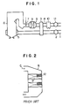
- the amount of NOx increases owing to the poor combustibility of the coal fuel itself, and also in the gas turbine plants, a large amount of NOx is contained in the flue gas, as in the coal-fired boilers, owing to a large amount of oxygen used and combustion at a higher temperature. That is, an apparatus for removing NOx, for example, as shown in Fig. 1, is usually installed in the power plant.
- Air for combustion in an air duct 1 is pressurized by a forcing draft fan (FDF) 2, heated by an air preheater 3 through heat exchange with the flue gas passing through a flue gas duct 4, and then supplied to a boiler 6 from a wind box (W/B) 5.
- FDF forcing draft fan
- W/B wind box
- the combustion flue gas from the boiler 6 is passed through the flue gas duct 4, subjected to NOx removal by NH 3 injected from a NH 3 injection tube 7 while the removal of NOx is accelerated by a catalyst 9 in an NOx removal reactor 8, provided at the downstream side of the NH 3 injection tube 7, and passed through the air preheater (A/H) 3 and an electrostatic precipitator (EP) 10 after the removal of NOx from the flue gas, pressurized by an inducing draft fan (IDF) 11 and vented to the atmosphere.
- A/H air preheater
- EP electrostatic precipitator
- Reaction temperature range for the NOx removal reactor 8 in the apparatus somewhat depends on the species of catalyst 9, but the temperature range of highest NOx removal efficiency is a relatively high and very narrqw, such as 300° to 400°C.
- the flue gas temperature widely fluctuates, depending on changes in the load, and often fails to fall within the said applicable reaction temperature range of catalyst 9.
- Deteriorating components such as alkali metals, etc. dissolved in the steam or water leaked from the tubes flow into the NOx removal reactor 8 through the flue gas duct 4 and deteriorate the catalyst 9.
- the activity of the catalyst used in the reactor is gradually lowered with time, as the operation of boiler 6 is continued, and thus it is necessary to provide a means for monitoring the activity of catalyst 9 to determine the timing of exchanging the catalyst 9 or regenerating the catalyst 9.
- the performance of catalyst 9 is lowered by a sudden accident, etc. in the boiler 6, as described above, it is important to investigate causes to lower the catalyst performance and take an immediate measure to cope with the causes. In any case, it is a key to investigate the performance of catalyst 9 itself. It is the ordinary expedient to sample the catalyst 9 periodically or when required to monitor or detect the deterioration in performance of catalyst 9.
- the catalyst 9 is usually packed in catalyst packages of integrated structure in the reactor 8 so that no clearances may be formed between the catalyst packages to prevent a gas leakage therebetween.
- the catalyst 9 is provided at a plurality of stages to facilitate exchanging of catalyst 9 in the case of catalyst deterioration.
- the flue gas passes through such a plurality of stages of the catalyst 9 at an equal flow rate, but since the catalyst-deteriorating components contained in the flue gas are adsorbed onto the catalyst 9 to some degree, the influence of the flue gas properties on the catalyst activity differs between the catalyst stage near the inlet of the reactor and that near the outlet of the reactor 8, and thus the degree of catalyst deterioration differs from one catalyst stage to another in the reactor 8. If detailed data how the catalyst deterioration is distributed throughout the reactor 8 are available, the catalyst performance can be economically controlled by exchanging only the deteriorated catalyst, etc.
- catalyst test pieces 12 for sampling must be provided at so many positions throughout the reactor 8, complicating the structure of reactor 8 and consuming much labor and time in taking out the so many distributed catalyst test pieces 12 from the catalyst packages for the sampling.
- catalyst must be filled into the sampled spaces to prevent a gas flow disturbance and maintain the performance.
- a larger amount of catalyst must be made ready for operation. Such a measure is actually quite impossible.
- An object of the present invention is to provide an apparatus for removing NOx which can overcome the problems of the prior art, that is, which can monitor deterioration of catalyst even during the operation and can take out catalyst test pieces without discontinuing the operation of the apparatus.
- the object of the present invention can be achieved by an apparatus for removing nitrogen oxides from a flue gas, which comprises an ammonia injection tube in a flue gas duct, a nitrogen oxide removal reactor containing a catalyst at the downstream side of the ammonia injection tube, and catalyst test pieces, characterized in that a bracket en-casing said catalyst test pieces is provided in the reactor and fixed to the reactor in a detachable mannerfrom the outside of the reactor.
- the downstream side of the reactor is open to the atmosphere and a sealing pipe is provided for injecting air into the reactor around the bracket support positions when the bracket is isolated from the reactor, the sealing pipe being open at the position at which the reactor supports the bracket.
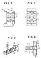
- Figs. 3 and 4 one embodiment of the present invention in a vertical flow type, NOx removal reactor is shown.
- the catalyst 9 and catalyst test pieces 12 are provided as separated from one another in the reactor 8 and the catalyst test pieces 12 are inserted into brackets 13.
- One end of the bracket 13 is positioned inside the reactor 8 to cross the flue gas stream at the right angle thereto.
- the bracket is shown in a perspective view, where the bracket 13 comprises a flange 14 and 4 L-shaped steel bars 15 supported by the flange 14 at one end so that the flue gas G can freely pass through the bracket 13.
- the bracket 13 is fixed in a detachable manner to the outer casing 16 of the reactor 8 by means of the flange 14.
- the bracket 13 is withdrawn outwardly from the reactor 8 by disengaging bolts and nuts at the flange 14, and the catalyst test pieces 12 are taken out of the withdrawn bracket 13.
- the catalyst test pieces 12 shown in Figs. 5 and 6 are of a plate type having a size of, for example, 100 mm x 100 mm.
- the size, species and shape of the catalyst are not particularly limited.
- numeral 18 is an inner casing and 19 is a heat-insulating material.
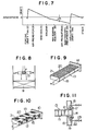
- Fig. 7 shows a draft pressure drop characteristic diagram of the individual units, plotted in relation to the draft on the ordinate and the positions of the individual units in an equilibrium draft system in a boiler plant on the abscissa.
- the position at the NOx removal reactor 8 is provided as lower in pressure (in minus pressure) only by L1P, than the atmospheric pressure (zero).
- the deterioration of catalyst 9 can be monitored by means of catalyst test pieces 12 by withdrawing the bracket 13 from the NOx removal reactor 8 even during the operation of the boiler plant, and thus the catalyst test piece 12 can be taken out from the withdrawn bracket for sampling while continuing NOx removal by the catalyst 9 in the NOx removal reactor 8.
- bracket 13 according to the present invention can be also applied to a honeycomb type catalyst, a pellet type catalyst by modifying the shape of catalyst test piece 12.
- Pressure drop on the catalyst test piece shown in Fig. 8 depends on the void ratio s of catalyst test piece 12 in the gas flow direction, the length m of catalyst test piece 12 in the gas flow direction, etc., but the pressure drop LP can be made smaller by shortening the length of catalyst test piece 12.
- the present invention is well applicable even to the honeycomb type catalyst and the pellet type catalyst which are generally considered to have a large pressure drop AP.
- Fig. 9 shows an application of the present invention to the honeycomb type catalyst and Fig. 10 that to the pellet type catalyst.
- catalyst test pieces 12 are placed in a case 21 enclosed with wire nettings 20.
- Fig. 11 is a side view of another embodiment of Fig. 6, where numerals 10 to 19 correspond to the same members as shown in Fig. 6, and numeral 22 is sealing pipes and 23 valves.
- Figs. 3 to 10 applications of the present invention to a boiler plant based on the equilibrium draft system are shown, whereas in Fig. 11 an application of the present invention to a boiler plant based on the forced draft system where drafting is carried out only with FDF 2 without using IDF 11 of Fig. 1 is shown. That is, in a boiler 6 drafted only with FDF 2, the position at which the NOx removal reactor 8 is located has a higher pressure than the atmospheric pressure.
- sealing air is injected to the bracket support positions from the sealing pipes 22 by opening the valves 23 in the sealing pipes 22.
- the flue gas can be prevented from discharging from the reactor by the sealing air injected around the bracket support positions.
- the catalyst can be monitored by withdrawing the bracket 13 and taking out the catalyst test piece 12 from the withdrawn bracket 13.
- deterioration of catalyst can be monitored during the operation of a boiler plant and sampling of catalyst can be carried out through catalyst test pieces without discontinuing the operation of an apparatus for removing NOx by providing brackets casing the catalyst test pieces in an NOx removal reactor.
Landscapes
- Engineering & Computer Science (AREA)
- Chemical & Material Sciences (AREA)
- Environmental & Geological Engineering (AREA)
- General Chemical & Material Sciences (AREA)
- Biomedical Technology (AREA)
- Analytical Chemistry (AREA)
- Health & Medical Sciences (AREA)
- Oil, Petroleum & Natural Gas (AREA)
- Chemical Kinetics & Catalysis (AREA)
- Exhaust Gas Treatment By Means Of Catalyst (AREA)
- Treating Waste Gases (AREA)
- Solid-Sorbent Or Filter-Aiding Compositions (AREA)
- Investigating Or Analyzing Non-Biological Materials By The Use Of Chemical Means (AREA)
Claims (8)
Priority Applications (1)
| Application Number | Priority Date | Filing Date | Title |
|---|---|---|---|
| AT85114318T ATE54837T1 (de) | 1984-11-12 | 1985-11-11 | Apparat zum entfernen von stickoxiden. |
Applications Claiming Priority (2)
| Application Number | Priority Date | Filing Date | Title |
|---|---|---|---|
| JP236824/84 | 1984-11-12 | ||
| JP59236824A JPH0615015B2 (ja) | 1984-11-12 | 1984-11-12 | 触媒サンプリング装置 |
Publications (3)
| Publication Number | Publication Date |
|---|---|
| EP0190413A2 EP0190413A2 (de) | 1986-08-13 |
| EP0190413A3 EP0190413A3 (en) | 1988-01-07 |
| EP0190413B1 true EP0190413B1 (de) | 1990-07-25 |
Family
ID=17006324
Family Applications (1)
| Application Number | Title | Priority Date | Filing Date |
|---|---|---|---|
| EP85114318A Expired - Lifetime EP0190413B1 (de) | 1984-11-12 | 1985-11-11 | Apparat zum Entfernen von Stickoxiden |
Country Status (5)
| Country | Link |
|---|---|
| US (1) | US4726935A (de) |
| EP (1) | EP0190413B1 (de) |
| JP (1) | JPH0615015B2 (de) |
| AT (1) | ATE54837T1 (de) |
| DE (1) | DE3578897D1 (de) |
Families Citing this family (14)
| Publication number | Priority date | Publication date | Assignee | Title |
|---|---|---|---|---|
| JP2637119B2 (ja) * | 1987-11-12 | 1997-08-06 | バブコツク日立株式会社 | 脱硝反応装置 |
| US5120516A (en) * | 1990-01-08 | 1992-06-09 | Physical Sciences, Inc. | Process for removing nox emissions from combustion effluents |
| US5213780A (en) * | 1991-06-04 | 1993-05-25 | Research-Cottrell, Inc. | Method for nitrogen oxide reduction and flue gas reheating |
| AU5897100A (en) * | 1999-08-10 | 2001-03-05 | Alstom Power Inc. | Method for controlling the catalytic treatment of flue gas |
| AU7869100A (en) * | 1999-10-08 | 2001-04-23 | Huntsman Petrochemical Corporation | In-situ process probes |
| US20020044886A1 (en) * | 2000-10-16 | 2002-04-18 | William Larco | Vaporization system having blower positioned in reduced temperature zone |
| US20020159923A1 (en) * | 2001-02-26 | 2002-10-31 | Platvoet Erwin M.J. | Gas phase reactor and process for reducing nitrogen oxide in a gas stream |
| US6663839B2 (en) | 2001-02-26 | 2003-12-16 | Abb Lummus Global Inc. | Radial flow gas phase reactor and method for reducing the nitrogen oxide content of a gas |
| US6706246B2 (en) | 2001-02-26 | 2004-03-16 | Abb Lummus Global Inc. | System and method for the selective catalytic reduction of nitrogen oxide in a gas stream |
| US6821490B2 (en) * | 2001-02-26 | 2004-11-23 | Abb Lummus Global Inc. | Parallel flow gas phase reactor and method for reducing the nitrogen oxide content of a gas |
| JP3935417B2 (ja) * | 2002-11-01 | 2007-06-20 | 中国電力株式会社 | 脱硝触媒管理方法および脱硝触媒管理装置 |
| FR2946547B1 (fr) * | 2009-06-10 | 2012-09-21 | Inst Francais Du Petrole | Systeme de rigidification des plateaux d'une colonne multi-etagee de grand diametre. |
| US10634029B2 (en) * | 2016-08-23 | 2020-04-28 | General Electric Technology Gmbh | Mobile selective catalyst reduction system |
| CN109613170A (zh) * | 2018-12-29 | 2019-04-12 | 浙江浙能兰溪发电有限责任公司 | 一种脱硝催化剂性能监测装置 |
Family Cites Families (11)
| Publication number | Priority date | Publication date | Assignee | Title |
|---|---|---|---|---|
| US2753246A (en) * | 1951-06-30 | 1956-07-03 | Standard Oil Co | Continuous carbon-on-catalyst analyzer |
| US2873248A (en) * | 1953-09-03 | 1959-02-10 | Exxon Research Engineering Co | Method of controlling oxidation state of hydroforming catalysts |
| US3787183A (en) * | 1972-02-09 | 1974-01-22 | Catalyst Services Inc | Method of analyzing catalyst action |
| JPS5154073A (de) * | 1974-11-06 | 1976-05-12 | Sumitomo Chemical Co | |
| DE2512410C3 (de) * | 1975-03-21 | 1985-04-18 | Didier Engineering Gmbh, 4300 Essen | Verfahren zur Entfernung von Stickoxiden und Anlage zur Durchführung des Verfahrens |
| JPS5824174B2 (ja) * | 1977-08-31 | 1983-05-19 | 三菱重工業株式会社 | 排ガス処理法 |
| JPS54103775A (en) * | 1978-02-03 | 1979-08-15 | Nippon Steel Corp | Contact reactor |
| JPS556042U (de) * | 1978-06-27 | 1980-01-16 | ||
| JPS562600A (en) * | 1979-06-21 | 1981-01-12 | Hitachi Cable | Exchanging port structure of operation member in shielding box |
| SU927293A1 (ru) * | 1980-09-08 | 1982-05-15 | За витель ::.; I | Реактор |
| DE3337793A1 (de) * | 1983-10-18 | 1985-05-02 | L. & C. Steinmüller GmbH, 5270 Gummersbach | Verfahren zur regelung der zugabemenge an reduktionsmittel bei der katalytischen reduktion von in rauchgasen enthaltenem no(pfeil abwaerts)x(pfeil abwaerts) |
-
1984
- 1984-11-12 JP JP59236824A patent/JPH0615015B2/ja not_active Expired - Lifetime
-
1985
- 1985-11-08 US US06/798,243 patent/US4726935A/en not_active Expired - Lifetime
- 1985-11-11 DE DE8585114318T patent/DE3578897D1/de not_active Expired - Lifetime
- 1985-11-11 AT AT85114318T patent/ATE54837T1/de not_active IP Right Cessation
- 1985-11-11 EP EP85114318A patent/EP0190413B1/de not_active Expired - Lifetime
Also Published As
| Publication number | Publication date |
|---|---|
| ATE54837T1 (de) | 1990-08-15 |
| EP0190413A2 (de) | 1986-08-13 |
| JPH0615015B2 (ja) | 1994-03-02 |
| DE3578897D1 (de) | 1990-08-30 |
| US4726935A (en) | 1988-02-23 |
| EP0190413A3 (en) | 1988-01-07 |
| JPS61114717A (ja) | 1986-06-02 |
Similar Documents
| Publication | Publication Date | Title |
|---|---|---|
| EP0190413B1 (de) | Apparat zum Entfernen von Stickoxiden | |
| US4353207A (en) | Apparatus for removing NOx and for providing better plant efficiency in simple cycle combustion turbine plants | |
| RU2149312C1 (ru) | Усовершенствования в сжигании и утилизации топливных газов | |
| US5078973A (en) | Apparatus for treating flue gas | |
| CN101109742B (zh) | 分仓式脱硝催化剂测试分析方法 | |
| US5286458A (en) | Injection type non-catalyst denitrogen oxide process control system | |
| GB2082084A (en) | Apparatus for recovering heat energy and removing nox in combined cycle plants | |
| CN102042605A (zh) | 回转式空气预热器分侧热清灰方法 | |
| US5673634A (en) | Incineration plant with heat exchanger | |
| KR100597961B1 (ko) | 고정원에서 발생되는 이산화질소 가시매연 저감방법 | |
| JPS5828514B2 (ja) | ユウガイブツシツガンユウリヨウノスクナイハイガスオ タイキチユウヘドウシユツスルホウホウ オヨビ ソウチ | |
| EP1565250B1 (de) | Abgasbehandlungssystem | |
| EP0189917B1 (de) | Vorrichtung zur Behandlung von Rauchgas | |
| KR20220118317A (ko) | 동작 동안 교체 가능한 촉매 유닛을 갖는 반응기 및 촉매 유닛을 교체하는 방법 | |
| CN219848972U (zh) | 带直燃热解析的分仓式scr脱硝装置 | |
| KR19980032281A (ko) | 회전 재생식 열교환기에 의한 배기 가스 처리 장치 | |
| CN111992026B (zh) | 实现在线切换的脱硝双反应器排布方法及系统 | |
| CN210645755U (zh) | 一种活性焦快速排料结构及活性焦排料系统 | |
| KR0170083B1 (ko) | 고온집진기의 가열 탈진장치 | |
| JPS591645A (ja) | 銅製錬転炉用排熱回収装置 | |
| CN223691080U (zh) | 热分解硫酸氢铵后的空预器三防解决系统 | |
| CN211586033U (zh) | 一种锅炉烟气脱硝装置 | |
| JP3480542B2 (ja) | ガスタービン用脱硝装置 | |
| JP3408845B2 (ja) | 排ガス浄化装置とその運転方法 | |
| JPH0811171B2 (ja) | アンモニアの注入量制御装置 |
Legal Events
| Date | Code | Title | Description |
|---|---|---|---|
| PUAI | Public reference made under article 153(3) epc to a published international application that has entered the european phase |
Free format text: ORIGINAL CODE: 0009012 |
|
| AK | Designated contracting states |
Kind code of ref document: A2 Designated state(s): AT DE GB IT |
|
| PUAL | Search report despatched |
Free format text: ORIGINAL CODE: 0009013 |
|
| AK | Designated contracting states |
Kind code of ref document: A3 Designated state(s): AT DE GB IT |
|
| 17P | Request for examination filed |
Effective date: 19880502 |
|
| 17Q | First examination report despatched |
Effective date: 19890123 |
|
| GRAA | (expected) grant |
Free format text: ORIGINAL CODE: 0009210 |
|
| AK | Designated contracting states |
Kind code of ref document: B1 Designated state(s): AT DE GB IT |
|
| REF | Corresponds to: |
Ref document number: 54837 Country of ref document: AT Date of ref document: 19900815 Kind code of ref document: T |
|
| ITF | It: translation for a ep patent filed | ||
| REF | Corresponds to: |
Ref document number: 3578897 Country of ref document: DE Date of ref document: 19900830 |
|
| PLBE | No opposition filed within time limit |
Free format text: ORIGINAL CODE: 0009261 |
|
| STAA | Information on the status of an ep patent application or granted ep patent |
Free format text: STATUS: NO OPPOSITION FILED WITHIN TIME LIMIT |
|
| 26N | No opposition filed | ||
| ITTA | It: last paid annual fee | ||
| REG | Reference to a national code |
Ref country code: GB Ref legal event code: IF02 |
|
| PGFP | Annual fee paid to national office [announced via postgrant information from national office to epo] |
Ref country code: AT Payment date: 20040929 Year of fee payment: 20 |
|
| PGFP | Annual fee paid to national office [announced via postgrant information from national office to epo] |
Ref country code: GB Payment date: 20041110 Year of fee payment: 20 |
|
| PGFP | Annual fee paid to national office [announced via postgrant information from national office to epo] |
Ref country code: DE Payment date: 20050127 Year of fee payment: 20 |
|
| PG25 | Lapsed in a contracting state [announced via postgrant information from national office to epo] |
Ref country code: GB Free format text: LAPSE BECAUSE OF EXPIRATION OF PROTECTION Effective date: 20051110 |
|
| REG | Reference to a national code |
Ref country code: GB Ref legal event code: PE20 |