EP0190401A2 - Dispositif de sécurité pour un outil entrainé par un moteur - Google Patents
Dispositif de sécurité pour un outil entrainé par un moteur Download PDFInfo
- Publication number
- EP0190401A2 EP0190401A2 EP85113500A EP85113500A EP0190401A2 EP 0190401 A2 EP0190401 A2 EP 0190401A2 EP 85113500 A EP85113500 A EP 85113500A EP 85113500 A EP85113500 A EP 85113500A EP 0190401 A2 EP0190401 A2 EP 0190401A2
- Authority
- EP
- European Patent Office
- Prior art keywords
- relay
- safety device
- motor
- safety
- circuit
- Prior art date
- Legal status (The legal status is an assumption and is not a legal conclusion. Google has not performed a legal analysis and makes no representation as to the accuracy of the status listed.)
- Granted
Links
- 208000027418 Wounds and injury Diseases 0.000 abstract 1
- 230000006378 damage Effects 0.000 abstract 1
- 208000014674 injury Diseases 0.000 abstract 1
- 239000003990 capacitor Substances 0.000 description 4
- 238000010586 diagram Methods 0.000 description 4
- 230000001419 dependent effect Effects 0.000 description 2
- 238000011109 contamination Methods 0.000 description 1
- 238000010304 firing Methods 0.000 description 1
Images


Classifications
-
- H—ELECTRICITY
- H02—GENERATION; CONVERSION OR DISTRIBUTION OF ELECTRIC POWER
- H02H—EMERGENCY PROTECTIVE CIRCUIT ARRANGEMENTS
- H02H7/00—Emergency protective circuit arrangements specially adapted for specific types of electric machines or apparatus or for sectionalised protection of cable or line systems, and effecting automatic switching in the event of an undesired change from normal working conditions
- H02H7/08—Emergency protective circuit arrangements specially adapted for specific types of electric machines or apparatus or for sectionalised protection of cable or line systems, and effecting automatic switching in the event of an undesired change from normal working conditions for dynamo-electric motors
- H02H7/093—Emergency protective circuit arrangements specially adapted for specific types of electric machines or apparatus or for sectionalised protection of cable or line systems, and effecting automatic switching in the event of an undesired change from normal working conditions for dynamo-electric motors against increase beyond, or decrease below, a predetermined level of rotational speed
Definitions
- the invention relates to a safety device for an electromotive tool, in particular a hand tool, according to the preamble of claim 1.
- Known power tools are switched on and off via a main switch.
- the motor is controlled via control electronics that control their actual values, e.g. B. receives from a tachometer generator. If the control electronics fail, the speed of the motor may increase to an unacceptable extent. This means that e.g. B. with angle grinders, the speed can become so high that the grinding wheel bursts. Therefore, the demand was made that the engine is switched off in the event of failure of the control electronics.
- centrifugal switch as already described in DE-PS 638 928, offers a solution for this.
- this type of engine speed-dependent shutdown is very complex and therefore very expensive due to the mechanical parts. This arrangement is also very susceptible to contamination. B. on the functional accuracy.
- the solution found is characterized in that a relay is arranged parallel to the motor, which acts on the power supply to the motor via a relay contact.
- the relay is controlled by a tachometer generator and a safety circuit connected to it.
- the safety circuit consists of a resonant circuit for the tachometer generator, a rectifier, a threshold switch, an ignition amplifier and a power unit.
- the pulse coming from the power section excites the relay, which then is held on the one hand and on the other hand cuts the power supply to the motor.
- the self-holding of the relay continues until the main switch is interrupted.
- Another advantageous solution is obtained by arranging the safety circuit in series with the main switch.
- the relay is activated via the main switch and thus enables the power supply for the motor. If the set maximum value for the speed is reached, in this case a thyristor, which is arranged in parallel to the relay, conducts the current past the relay so that the relay drops out and the power supply to the motor is interrupted, despite the main switch being switched on.
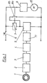
- a first embodiment of the safety device is shown schematically.
- the tachometer generator 1 provides an analog signal for the actual rotation Number of motor 10. This signal is converted via the resonant circuit 2 and the converter 3 into a direct current signal and meets a threshold switch 4. If the value selected by the threshold switch 4 is exceeded, the power unit 5 receives a signal via the ignition amplifier 11.
- Das Power section 5, here for example a triac then no longer blocks the passage to the relay 7 lying in series, so that the relay 7 can pick up and interrupt the power supply to the motor 10 via the relay contact 8a. So that the motor 10 does not start again when the speed falls below the set speed, not only the relay contact 8a but also the relay contact 8b is actuated when the relay 7 is pulled up. With the relay contact 8b, the power section 5 is bridged, so that the relay 7 remains locked until the main switch 6 is opened.
- Fig. 2 shows the embodiment of Fig.1.
- the inductance L and the capacitor C1 form the resonant circuit 2.
- the resonance frequency of the resonant circuit can be determined by the choice of the capacitor C1.
- the steep rise in resonance of the tacho voltage around the switch-off point / favors the switching behavior of the subsequent threshold switch 4.
- the induced tacho voltage is rectified in converter 3 and can be set via the voltage divider R1 and R2.
- the resistance value that is set at resistor R1 is used to eliminate motor leakage.
- the measure for the threshold voltage is indicated by the Zener diode D2.
- the subsequent amplifier circuit which is formed by the transistor T2, the resistors R5 and R6 and the capacitor C3, ignites the triac 5 when the threshold value is reached.
- FIG. 3 A second embodiment is shown in FIG. 3.
- the safety device here consists of the same elements as in the aforementioned example.
- the switch-off signal Via a tachometer generator 21, a resonant circuit 22, a rectifier 23 and an adjustable threshold switch 24, the switch-off signal reaches an ignition amplifier 31 which, however, gives a signal to a thyristor 25 when the permissible speed is exceeded.
- the thyristor 25 becomes conductive, the potential at the parallel relay 27 drops and the relay contact 28 opens.
- the power supply to the motor 30 is interrupted.
- the current flow through the main switch 26 now runs through the thyristor 25.
- the load circuit remains interrupted until the main switch 26 is switched on again.
- FIG. 4 shows the embodiment according to FIG. 3 in a discrete structure and differs from that in FIG. 2 Embodiment shown in that the amplifier circuit 31 consists of the transistor T2, the resistors R6 and R7 and the capacitor C3, which supplies the firing pulse for the thyristor 25.
- the thyristor 25 can be replaced by a transistor circuit with which the power supply for the relay 27 can be short-circuited.
- the circuits shown in the two exemplary embodiments of the safety device represent an inexpensive, functionally reliable and easy-to-implement addition to existing control electronics 9, 29 in the power tool.
Landscapes
- Finish Polishing, Edge Sharpening, And Grinding By Specific Grinding Devices (AREA)
- Ignition Installations For Internal Combustion Engines (AREA)
- Protection Of Generators And Motors (AREA)
- Control Of Electric Motors In General (AREA)
- Control Of Direct Current Motors (AREA)
Applications Claiming Priority (2)
| Application Number | Priority Date | Filing Date | Title |
|---|---|---|---|
| DE3504074A DE3504074C2 (de) | 1985-02-07 | 1985-02-07 | Sicherheitseinrichtung für ein elektromotorisch angetriebenes Werkzeug |
| DE3504074 | 1985-02-07 |
Publications (3)
| Publication Number | Publication Date |
|---|---|
| EP0190401A2 true EP0190401A2 (fr) | 1986-08-13 |
| EP0190401A3 EP0190401A3 (en) | 1987-08-19 |
| EP0190401B1 EP0190401B1 (fr) | 1990-02-28 |
Family
ID=6261847
Family Applications (1)
| Application Number | Title | Priority Date | Filing Date |
|---|---|---|---|
| EP85113500A Expired - Lifetime EP0190401B1 (fr) | 1985-02-07 | 1985-10-24 | Dispositif de sécurité pour un outil entrainé par un moteur |
Country Status (4)
| Country | Link |
|---|---|
| US (1) | US4847721A (fr) |
| EP (1) | EP0190401B1 (fr) |
| JP (1) | JPS61182758A (fr) |
| DE (1) | DE3504074C2 (fr) |
Cited By (2)
| Publication number | Priority date | Publication date | Assignee | Title |
|---|---|---|---|---|
| GB2237156A (en) * | 1989-10-17 | 1991-04-24 | Samsung Electronics Co Ltd | Control apparatus for food processing apparatus |
| DE4021560A1 (de) * | 1990-07-06 | 1992-01-16 | Telefunken Electronic Gmbh | Elektrisches werkzeug mit motorantrieb |
Families Citing this family (11)
| Publication number | Priority date | Publication date | Assignee | Title |
|---|---|---|---|---|
| DE3520099A1 (de) * | 1985-06-05 | 1986-12-11 | C. & E. Fein Gmbh & Co, 7000 Stuttgart | Sicherheitseinrichtung fuer ein elektromotorisch angetriebenes werkzeug |
| DE3937446A1 (de) * | 1989-11-10 | 1991-05-16 | Peter Neef | Verfahren und vorrichtung zur erweiterung einer stillstands-schutzfunktion fuer elektromotoren |
| DE4132208C1 (fr) * | 1991-09-27 | 1993-02-04 | Fraunhofer-Gesellschaft Zur Foerderung Der Angewandten Forschung Ev, 8000 Muenchen, De | |
| JPH07274571A (ja) * | 1994-03-30 | 1995-10-20 | Matsushita Electric Ind Co Ltd | 回転センサー付直流モータ |
| US5744921A (en) * | 1996-05-02 | 1998-04-28 | Siemens Electric Limited | Control circuit for five-phase brushless DC motor |
| US7075195B2 (en) * | 2002-01-14 | 2006-07-11 | Safestart System, Llc | Electrical safety lockout mechanism for power tools and other hazardous machinery |
| CA2530341A1 (fr) * | 2004-12-15 | 2006-06-15 | David Chandler Paul | Scie arasante |
| US10369718B2 (en) | 2004-12-15 | 2019-08-06 | Canis Major Tool Company Llc | Flush cut saw |
| BR102012027771A2 (pt) * | 2012-10-29 | 2014-06-24 | Delphi Tech Inc | Sistema e método para controle de um motor elétrico |
| US9555554B2 (en) | 2013-05-06 | 2017-01-31 | Milwaukee Electric Tool Corporation | Oscillating multi-tool system |
| EP3299127A1 (fr) | 2016-06-24 | 2018-03-28 | Black & Decker Inc. | Schéma de commande de fonctionnement d'outil électrique sans fil sur la base de la température de la batterie |
Citations (2)
| Publication number | Priority date | Publication date | Assignee | Title |
|---|---|---|---|---|
| US2818535A (en) * | 1955-08-01 | 1957-12-31 | Westinghouse Electric Corp | Safety control circuits for electric motors |
| US4020404A (en) * | 1974-04-24 | 1977-04-26 | Richard Wilke | System for controlling motor speed |
Family Cites Families (11)
| Publication number | Priority date | Publication date | Assignee | Title |
|---|---|---|---|---|
| DE1248782B (fr) * | ||||
| DE638928C (de) * | 1934-11-16 | 1936-11-25 | Fein C & E | Fliehkraftschalter, insbesondere fuer Elektromotoren, mit in axialer Richtung schwingendem Fliehkoerper |
| US3284668A (en) * | 1963-10-28 | 1966-11-08 | Bendix Corp | Electronic speed sensor |
| FR1557850A (fr) * | 1968-01-02 | 1969-02-21 | ||
| US3958164A (en) * | 1974-12-10 | 1976-05-18 | Bethlehem Steel Corporation | Protective panel circuit |
| US4161681A (en) * | 1977-03-17 | 1979-07-17 | General Electric Company | Prime mover, method of operating such and circuit |
| US4196462A (en) * | 1978-05-30 | 1980-04-01 | General Electric Company | Protective control circuit for induction motors |
| JPS56109854U (fr) * | 1980-01-19 | 1981-08-25 | ||
| US4412158A (en) * | 1980-02-21 | 1983-10-25 | Black & Decker Inc. | Speed control circuit for an electric power tool |
| JPS5717018A (en) * | 1980-07-07 | 1982-01-28 | Richo Denshi Kogyo Kk | Method and device for preventing runaway of machine tool |
| DE3520099A1 (de) * | 1985-06-05 | 1986-12-11 | C. & E. Fein Gmbh & Co, 7000 Stuttgart | Sicherheitseinrichtung fuer ein elektromotorisch angetriebenes werkzeug |
-
1985
- 1985-02-07 DE DE3504074A patent/DE3504074C2/de not_active Expired - Fee Related
- 1985-10-24 EP EP85113500A patent/EP0190401B1/fr not_active Expired - Lifetime
- 1985-12-27 JP JP60299624A patent/JPS61182758A/ja active Granted
-
1987
- 1987-08-12 US US07/086,190 patent/US4847721A/en not_active Expired - Fee Related
Patent Citations (2)
| Publication number | Priority date | Publication date | Assignee | Title |
|---|---|---|---|---|
| US2818535A (en) * | 1955-08-01 | 1957-12-31 | Westinghouse Electric Corp | Safety control circuits for electric motors |
| US4020404A (en) * | 1974-04-24 | 1977-04-26 | Richard Wilke | System for controlling motor speed |
Cited By (3)
| Publication number | Priority date | Publication date | Assignee | Title |
|---|---|---|---|---|
| GB2237156A (en) * | 1989-10-17 | 1991-04-24 | Samsung Electronics Co Ltd | Control apparatus for food processing apparatus |
| GB2237156B (en) * | 1989-10-17 | 1993-09-08 | Samsung Electronics Co Ltd | Improvements relating to food processing apparatus |
| DE4021560A1 (de) * | 1990-07-06 | 1992-01-16 | Telefunken Electronic Gmbh | Elektrisches werkzeug mit motorantrieb |
Also Published As
| Publication number | Publication date |
|---|---|
| DE3504074A1 (de) | 1986-08-07 |
| DE3504074C2 (de) | 1993-10-21 |
| EP0190401A3 (en) | 1987-08-19 |
| JPH0543456B2 (fr) | 1993-07-01 |
| US4847721A (en) | 1989-07-11 |
| EP0190401B1 (fr) | 1990-02-28 |
| JPS61182758A (ja) | 1986-08-15 |
Similar Documents
| Publication | Publication Date | Title |
|---|---|---|
| EP0190401A2 (fr) | Dispositif de sécurité pour un outil entrainé par un moteur | |
| DE2047586C3 (de) | Zündanlage für Brennkraftmaschinen | |
| DE3900780A1 (de) | Schutzeinrichtung fuer den anlasser eines motors | |
| DE59541T1 (de) | Schutzsystem fuer eine automatische werkzeugwechselvorrichtung. | |
| EP0048793B1 (fr) | Suppresseur de démarrage d'appareils électriques après une panne de courant | |
| EP0562063B1 (fr) | Systeme de commande pour la pompe de carburant electrique d'un moteur a combustion interne | |
| EP0205730B1 (fr) | Dispositif de sécurité pour un outil commandé par un moteur électrique | |
| DE2340214A1 (de) | Zuendanordnung fuer brennkraftmaschine | |
| EP0391065A3 (fr) | Dispositif de distribution pour élever une tension d'alimentation | |
| DE2458068A1 (de) | Batterieladesystem fuer kraftfahrzeug | |
| DE2453979A1 (de) | Spannungswandler, insbesondere fuer elektrofahrzeuge | |
| DE2952791A1 (de) | Einrichtung zum schutz gegen ueberspannungen | |
| DE69809985T2 (de) | Elektronisch gesteuerter Anlasser für Kraftfahrzeug | |
| CH626199A5 (fr) | ||
| DE2825830A1 (de) | Zuendeinrichtung fuer brennkraftmaschinen | |
| EP0141166A2 (fr) | Agencement de commutation pour outils électriques | |
| DE3206187A1 (de) | Anlassvorrichtung | |
| DE3428898A1 (de) | Elektrische sicherheitseinrichtung fuer ein deichselgefuehrt verfahrbares staplerfahrzeug | |
| DE69811193T2 (de) | Verbesserungen an Steuervorrichtungen für Anlasser von Kraftfahrzeugen | |
| DE2546987A1 (de) | Einrichtung zum regeln der fahrgeschwindigkeit eines kraftfahrzeuges | |
| DE2415138C3 (de) | Anordnung zur Drehzahlsteuerung eines Universalmotors | |
| DE4019914C2 (fr) | ||
| DE2351106C3 (de) | AnIaB- und Schutzeinrichtung für einen Gleichstrommotor | |
| DE2557669A1 (de) | Schaltungsanordnung zum einschalten einer elektrischen kraftstoffoerderpumpe | |
| DE2155223A1 (de) | Anordnung zur drehzahlbegrenzung von brennkraftmaschinen |
Legal Events
| Date | Code | Title | Description |
|---|---|---|---|
| PUAI | Public reference made under article 153(3) epc to a published international application that has entered the european phase |
Free format text: ORIGINAL CODE: 0009012 |
|
| AK | Designated contracting states |
Kind code of ref document: A2 Designated state(s): FR GB IT NL SE |
|
| PUAL | Search report despatched |
Free format text: ORIGINAL CODE: 0009013 |
|
| AK | Designated contracting states |
Kind code of ref document: A3 Designated state(s): FR GB IT NL SE |
|
| 17P | Request for examination filed |
Effective date: 19870727 |
|
| 17Q | First examination report despatched |
Effective date: 19881215 |
|
| GRAA | (expected) grant |
Free format text: ORIGINAL CODE: 0009210 |
|
| AK | Designated contracting states |
Kind code of ref document: B1 Designated state(s): FR GB IT NL SE |
|
| ITF | It: translation for a ep patent filed | ||
| ET | Fr: translation filed | ||
| GBT | Gb: translation of ep patent filed (gb section 77(6)(a)/1977) | ||
| PLBE | No opposition filed within time limit |
Free format text: ORIGINAL CODE: 0009261 |
|
| STAA | Information on the status of an ep patent application or granted ep patent |
Free format text: STATUS: NO OPPOSITION FILED WITHIN TIME LIMIT |
|
| 26N | No opposition filed | ||
| ITTA | It: last paid annual fee | ||
| PGFP | Annual fee paid to national office [announced via postgrant information from national office to epo] |
Ref country code: SE Payment date: 19940614 Year of fee payment: 10 |
|
| PGFP | Annual fee paid to national office [announced via postgrant information from national office to epo] |
Ref country code: FR Payment date: 19940922 Year of fee payment: 10 |
|
| PGFP | Annual fee paid to national office [announced via postgrant information from national office to epo] |
Ref country code: GB Payment date: 19941014 Year of fee payment: 10 |
|
| PGFP | Annual fee paid to national office [announced via postgrant information from national office to epo] |
Ref country code: NL Payment date: 19941031 Year of fee payment: 10 |
|
| EAL | Se: european patent in force in sweden |
Ref document number: 85113500.4 |
|
| PG25 | Lapsed in a contracting state [announced via postgrant information from national office to epo] |
Ref country code: GB Effective date: 19951024 |
|
| PG25 | Lapsed in a contracting state [announced via postgrant information from national office to epo] |
Ref country code: SE Effective date: 19951025 |
|
| PG25 | Lapsed in a contracting state [announced via postgrant information from national office to epo] |
Ref country code: NL Effective date: 19960501 |
|
| GBPC | Gb: european patent ceased through non-payment of renewal fee |
Effective date: 19951024 |
|
| PG25 | Lapsed in a contracting state [announced via postgrant information from national office to epo] |
Ref country code: FR Effective date: 19960628 |
|
| EUG | Se: european patent has lapsed |
Ref document number: 85113500.4 |
|
| NLV4 | Nl: lapsed or anulled due to non-payment of the annual fee |
Effective date: 19960501 |
|
| REG | Reference to a national code |
Ref country code: FR Ref legal event code: ST |