EP0190019A2 - Procédé et dispositif de manipulation de fluides - Google Patents
Procédé et dispositif de manipulation de fluides Download PDFInfo
- Publication number
- EP0190019A2 EP0190019A2 EP86300487A EP86300487A EP0190019A2 EP 0190019 A2 EP0190019 A2 EP 0190019A2 EP 86300487 A EP86300487 A EP 86300487A EP 86300487 A EP86300487 A EP 86300487A EP 0190019 A2 EP0190019 A2 EP 0190019A2
- Authority
- EP
- European Patent Office
- Prior art keywords
- support
- fluid
- sheet
- sample
- fluorescent
- Prior art date
- Legal status (The legal status is an assumption and is not a legal conclusion. Google has not performed a legal analysis and makes no representation as to the accuracy of the status listed.)
- Granted
Links
- 239000012530 fluid Substances 0.000 title claims abstract description 114
- 238000000034 method Methods 0.000 title claims description 19
- 238000002156 mixing Methods 0.000 claims description 22
- 238000013019 agitation Methods 0.000 claims description 3
- 238000000151 deposition Methods 0.000 claims 1
- 230000000694 effects Effects 0.000 claims 1
- 230000007723 transport mechanism Effects 0.000 abstract 1
- 239000002245 particle Substances 0.000 description 63
- 239000000523 sample Substances 0.000 description 63
- 210000003743 erythrocyte Anatomy 0.000 description 21
- 239000003153 chemical reaction reagent Substances 0.000 description 19
- 239000000427 antigen Substances 0.000 description 18
- 102000036639 antigens Human genes 0.000 description 18
- 108091007433 antigens Proteins 0.000 description 18
- 239000012491 analyte Substances 0.000 description 16
- 239000003446 ligand Substances 0.000 description 15
- 238000004458 analytical method Methods 0.000 description 13
- 210000004027 cell Anatomy 0.000 description 12
- 239000000835 fiber Substances 0.000 description 12
- 230000027455 binding Effects 0.000 description 11
- 230000007246 mechanism Effects 0.000 description 11
- 239000011324 bead Substances 0.000 description 10
- 239000000463 material Substances 0.000 description 10
- 238000004220 aggregation Methods 0.000 description 9
- 230000002776 aggregation Effects 0.000 description 9
- 239000013307 optical fiber Substances 0.000 description 9
- 230000005284 excitation Effects 0.000 description 7
- 239000002609 medium Substances 0.000 description 7
- 239000000243 solution Substances 0.000 description 7
- 238000001514 detection method Methods 0.000 description 6
- 210000004369 blood Anatomy 0.000 description 5
- 239000008280 blood Substances 0.000 description 5
- 239000003610 charcoal Substances 0.000 description 5
- 238000006243 chemical reaction Methods 0.000 description 5
- 239000000126 substance Substances 0.000 description 5
- 239000007788 liquid Substances 0.000 description 4
- 238000012360 testing method Methods 0.000 description 4
- 102000004856 Lectins Human genes 0.000 description 3
- 108090001090 Lectins Proteins 0.000 description 3
- 238000003556 assay Methods 0.000 description 3
- 238000011067 equilibration Methods 0.000 description 3
- 239000002523 lectin Substances 0.000 description 3
- 238000005259 measurement Methods 0.000 description 3
- 239000000203 mixture Substances 0.000 description 3
- 210000002966 serum Anatomy 0.000 description 3
- -1 urine Substances 0.000 description 3
- OALHHIHQOFIMEF-UHFFFAOYSA-N 3',6'-dihydroxy-2',4',5',7'-tetraiodo-3h-spiro[2-benzofuran-1,9'-xanthene]-3-one Chemical compound O1C(=O)C2=CC=CC=C2C21C1=CC(I)=C(O)C(I)=C1OC1=C(I)C(O)=C(I)C=C21 OALHHIHQOFIMEF-UHFFFAOYSA-N 0.000 description 2
- 238000010521 absorption reaction Methods 0.000 description 2
- 230000004323 axial length Effects 0.000 description 2
- 230000015572 biosynthetic process Effects 0.000 description 2
- 210000001124 body fluid Anatomy 0.000 description 2
- 239000010839 body fluid Substances 0.000 description 2
- 150000001875 compounds Chemical class 0.000 description 2
- 230000003247 decreasing effect Effects 0.000 description 2
- 238000009826 distribution Methods 0.000 description 2
- 238000005755 formation reaction Methods 0.000 description 2
- 239000007789 gas Substances 0.000 description 2
- 229920000126 latex Polymers 0.000 description 2
- 239000004816 latex Substances 0.000 description 2
- 238000012986 modification Methods 0.000 description 2
- 230000004048 modification Effects 0.000 description 2
- 230000003287 optical effect Effects 0.000 description 2
- 239000004033 plastic Substances 0.000 description 2
- 229920003023 plastic Polymers 0.000 description 2
- 229920002379 silicone rubber Polymers 0.000 description 2
- 239000004945 silicone rubber Substances 0.000 description 2
- 238000010561 standard procedure Methods 0.000 description 2
- 239000000758 substrate Substances 0.000 description 2
- 238000012546 transfer Methods 0.000 description 2
- VTRBOZNMGVDGHY-UHFFFAOYSA-N 6-(4-methylanilino)naphthalene-2-sulfonic acid Chemical compound C1=CC(C)=CC=C1NC1=CC=C(C=C(C=C2)S(O)(=O)=O)C2=C1 VTRBOZNMGVDGHY-UHFFFAOYSA-N 0.000 description 1
- CJIJXIFQYOPWTF-UHFFFAOYSA-N 7-hydroxycoumarin Natural products O1C(=O)C=CC2=CC(O)=CC=C21 CJIJXIFQYOPWTF-UHFFFAOYSA-N 0.000 description 1
- LEZXIGBHPBULCL-UHFFFAOYSA-N 9-phenyl-9h-xanthene-3,6-diamine Chemical compound C12=CC=C(N)C=C2OC2=CC(N)=CC=C2C1C1=CC=CC=C1 LEZXIGBHPBULCL-UHFFFAOYSA-N 0.000 description 1
- 241000894006 Bacteria Species 0.000 description 1
- 229910052693 Europium Inorganic materials 0.000 description 1
- 239000004793 Polystyrene Substances 0.000 description 1
- 239000002174 Styrene-butadiene Substances 0.000 description 1
- 229910052771 Terbium Inorganic materials 0.000 description 1
- 230000009471 action Effects 0.000 description 1
- 230000004520 agglutination Effects 0.000 description 1
- 125000003277 amino group Chemical group 0.000 description 1
- 238000013459 approach Methods 0.000 description 1
- 239000007864 aqueous solution Substances 0.000 description 1
- 238000000149 argon plasma sintering Methods 0.000 description 1
- 239000012911 assay medium Substances 0.000 description 1
- ZYGHJZDHTFUPRJ-UHFFFAOYSA-N benzo-alpha-pyrone Natural products C1=CC=C2OC(=O)C=CC2=C1 ZYGHJZDHTFUPRJ-UHFFFAOYSA-N 0.000 description 1
- 230000008033 biological extinction Effects 0.000 description 1
- 210000000601 blood cell Anatomy 0.000 description 1
- MTAZNLWOLGHBHU-UHFFFAOYSA-N butadiene-styrene rubber Chemical compound C=CC=C.C=CC1=CC=CC=C1 MTAZNLWOLGHBHU-UHFFFAOYSA-N 0.000 description 1
- 230000001413 cellular effect Effects 0.000 description 1
- 238000005119 centrifugation Methods 0.000 description 1
- 230000008859 change Effects 0.000 description 1
- 239000003795 chemical substances by application Substances 0.000 description 1
- 238000005253 cladding Methods 0.000 description 1
- 238000004140 cleaning Methods 0.000 description 1
- 238000010276 construction Methods 0.000 description 1
- 238000007796 conventional method Methods 0.000 description 1
- 235000001671 coumarin Nutrition 0.000 description 1
- 150000004775 coumarins Chemical class 0.000 description 1
- 238000010586 diagram Methods 0.000 description 1
- 230000004069 differentiation Effects 0.000 description 1
- 229920001971 elastomer Polymers 0.000 description 1
- 239000000806 elastomer Substances 0.000 description 1
- 230000005670 electromagnetic radiation Effects 0.000 description 1
- 239000007850 fluorescent dye Substances 0.000 description 1
- 238000007421 fluorometric assay Methods 0.000 description 1
- 239000011521 glass Substances 0.000 description 1
- 230000002401 inhibitory effect Effects 0.000 description 1
- 229920000592 inorganic polymer Polymers 0.000 description 1
- 230000001678 irradiating effect Effects 0.000 description 1
- 239000006249 magnetic particle Substances 0.000 description 1
- 229910052751 metal Inorganic materials 0.000 description 1
- 239000002184 metal Substances 0.000 description 1
- 150000002739 metals Chemical class 0.000 description 1
- 239000004005 microsphere Substances 0.000 description 1
- 239000011259 mixed solution Substances 0.000 description 1
- 239000002991 molded plastic Substances 0.000 description 1
- 150000005002 naphthylamines Chemical class 0.000 description 1
- 125000005184 naphthylamino group Chemical group C1(=CC=CC2=CC=CC=C12)N* 0.000 description 1
- 229920000620 organic polymer Polymers 0.000 description 1
- 230000036961 partial effect Effects 0.000 description 1
- 239000013618 particulate matter Substances 0.000 description 1
- 125000001997 phenyl group Chemical group [H]C1=C([H])C([H])=C(*)C([H])=C1[H] 0.000 description 1
- 229920000642 polymer Polymers 0.000 description 1
- 229920000193 polymethacrylate Polymers 0.000 description 1
- 229920002223 polystyrene Polymers 0.000 description 1
- 229920002635 polyurethane Polymers 0.000 description 1
- 239000004814 polyurethane Substances 0.000 description 1
- 238000002360 preparation method Methods 0.000 description 1
- 238000012545 processing Methods 0.000 description 1
- 230000001737 promoting effect Effects 0.000 description 1
- 238000006862 quantum yield reaction Methods 0.000 description 1
- 238000010791 quenching Methods 0.000 description 1
- 230000000171 quenching effect Effects 0.000 description 1
- 229910052761 rare earth metal Inorganic materials 0.000 description 1
- 150000002910 rare earth metals Chemical class 0.000 description 1
- 239000011541 reaction mixture Substances 0.000 description 1
- 230000002829 reductive effect Effects 0.000 description 1
- 230000000284 resting effect Effects 0.000 description 1
- 230000000717 retained effect Effects 0.000 description 1
- 238000009958 sewing Methods 0.000 description 1
- 230000009870 specific binding Effects 0.000 description 1
- 238000009987 spinning Methods 0.000 description 1
- 238000003756 stirring Methods 0.000 description 1
- 239000011115 styrene butadiene Substances 0.000 description 1
- 229920003048 styrene butadiene rubber Polymers 0.000 description 1
- 125000001424 substituent group Chemical group 0.000 description 1
- 239000000725 suspension Substances 0.000 description 1
- ORHBXUUXSCNDEV-UHFFFAOYSA-N umbelliferone Chemical compound C1=CC(=O)OC2=CC(O)=CC=C21 ORHBXUUXSCNDEV-UHFFFAOYSA-N 0.000 description 1
- HFTAFOQKODTIJY-UHFFFAOYSA-N umbelliferone Natural products Cc1cc2C=CC(=O)Oc2cc1OCC=CC(C)(C)O HFTAFOQKODTIJY-UHFFFAOYSA-N 0.000 description 1
- 210000002700 urine Anatomy 0.000 description 1
- 210000002845 virion Anatomy 0.000 description 1
- 239000001018 xanthene dye Substances 0.000 description 1
Images
Classifications
-
- G—PHYSICS
- G01—MEASURING; TESTING
- G01N—INVESTIGATING OR ANALYSING MATERIALS BY DETERMINING THEIR CHEMICAL OR PHYSICAL PROPERTIES
- G01N35/00—Automatic analysis not limited to methods or materials provided for in any single one of groups G01N1/00 - G01N33/00; Handling materials therefor
- G01N35/02—Automatic analysis not limited to methods or materials provided for in any single one of groups G01N1/00 - G01N33/00; Handling materials therefor using a plurality of sample containers moved by a conveyor system past one or more treatment or analysis stations
-
- B—PERFORMING OPERATIONS; TRANSPORTING
- B01—PHYSICAL OR CHEMICAL PROCESSES OR APPARATUS IN GENERAL
- B01L—CHEMICAL OR PHYSICAL LABORATORY APPARATUS FOR GENERAL USE
- B01L3/00—Containers or dishes for laboratory use, e.g. laboratory glassware; Droppers
- B01L3/50—Containers for the purpose of retaining a material to be analysed, e.g. test tubes
- B01L3/505—Containers for the purpose of retaining a material to be analysed, e.g. test tubes flexible containers not provided for above
-
- B—PERFORMING OPERATIONS; TRANSPORTING
- B01—PHYSICAL OR CHEMICAL PROCESSES OR APPARATUS IN GENERAL
- B01F—MIXING, e.g. DISSOLVING, EMULSIFYING OR DISPERSING
- B01F31/00—Mixers with shaking, oscillating, or vibrating mechanisms
- B01F31/30—Mixers with shaking, oscillating, or vibrating mechanisms comprising a receptacle to only a part of which the shaking, oscillating, or vibrating movement is imparted
- B01F31/31—Mixers with shaking, oscillating, or vibrating mechanisms comprising a receptacle to only a part of which the shaking, oscillating, or vibrating movement is imparted using receptacles with deformable parts, e.g. membranes, to which a motion is imparted
-
- B—PERFORMING OPERATIONS; TRANSPORTING
- B01—PHYSICAL OR CHEMICAL PROCESSES OR APPARATUS IN GENERAL
- B01F—MIXING, e.g. DISSOLVING, EMULSIFYING OR DISPERSING
- B01F33/00—Other mixers; Mixing plants; Combinations of mixers
Definitions
- the present invention relates to methods and apparatus for handling small fluid volumes.
- fluid encompasses liquids alone and liquids containing particulate matter of whatever kind but excludes gases.
- the invention relates to an apparatus and method which are utilized to mix small fluid volumes by applying a deformation force to a deformable support for the fluid and causing agitation and mixing of the fluid as it clings to the support during deformation.
- reaction cups are typically molded plastic about the size and shape of a sewing thimble. Sometimes they are of a special shape to include multiple compartments, viewing windows for optics, or shaped for centrifugation. They are usually loaded by hand into some form of automated mechanism although automatic loaders have been built. Complicated mechanisms have been built to move the cups between different locations so that various operations can be performed as required by the analysis method. At the end of the analysis, they must be carefully removed to prevent spilling of materials which may constitute a biohazard.
- the volumes of the cups are usually quite large, consisting of hundreds of microliters. Mixing of sample and reagents can be done in several ways: employment of centrifugal forces, turbulence due to hydraulic discharge, magnetic stir bars or mixing blades or paddles which require cleaning between successive samples. Discrete plastic cups have moderately thick walls and have poor thermal conductivity, making rapid temperature equilibration difficult even with waterbaths. Additionally, discrete cups can be relatively expensive costing from one to several cents each.
- the present invention affords a fluid handling system which minimizes, obviates or totally overcomes problems presented by the prior art devices. For example, it is possible to handle very small volumes of fluid, even sample volumes below 50 microliters.
- the apparatus promotes mixing of the fluid sample within itself or, if mixed with a reagent, without using any external mixer which is in contact with the reaction mixture. Additionally, the system yields an apparatus which promotes good thermal conductivity such that temperature gradients throughout the mixed system are minimized.
- the system additionally exhibits simple and safe disposal of used materials and facilitates lower costs through the use of disposables and reduced labor costs or machine costs due to the absence of discrete reaction cups.
- U.S. Patent No. 3,650,698 describes the dispensing of fluid samples and/or reagents onto a film strip containing quantities or spots of dried suspension of reaction intensifying agent, which may contain magnetic particles to promote mixing when subjected to an alternating magnetic field.
- U.S. Patent No. 3,854,703 describes a system in which a jet of gas is directed onto a fluid volume resting on a support to cause relative movement between the fluid and the support, thus promoting mixing of the fluid.
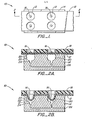
- Sheet 12 can include a semi-rigid or rigid portion 18, which is adapted to facilitate transport of sheet 12 relative to support 14, but yet expose limited areas of sheet 12.
- the exposed areas of sheet 12 are adapted to receive portions of fluid samples 16 which can be transported and positioned over wells 20.
- the vacuum source can be actuated to reduce the pressure within well 20, thus creating a pressure differential across the sheet and deforming sheet 12.
- actuation of the vacuum source reduces the pressure beneath sheet 12 and causes it to deform and extend into and conform to the contour of wells 20.
- the magnitude of the vacuum i.e. the deformation force
- the interfacial area between the fluid sample 16 and sheet 12 is also varied and physical agitation and mixing of the fluid is caused to occur.
- Support 14 can be provided with conventional temperature controls, such as water channels or electrical heaters, to afford and maintain the fluid volumes at a particular, desired temperature.
- conventional temperature controls such as water channels or electrical heaters, to afford and maintain the fluid volumes at a particular, desired temperature.
- very efficient heat transfer between support 14 and fluid sample 16 occurs.
- rapid thermal equilibration can be achieved within the fluid sample which is necessary for the accuracy of many chemical analyses.
- the stretching of sheet 12 over the surface contour of well 20 causes the thickness of sheet 12 to decrease and increases the rate of heat transfer between the fluid sample 16 and support 14.
- the magnitude of the pressure can be modulated with time as desired for a particular application to vary the elongation of sheet 12 within wells 20 to provide a thorough mixing action.
- fluid volumes of less than 100 microliters for conventional fluid samples and reagents utilized for analysis in clinical laboratories can be accommodated and can be supported on sheet 12 without the need for additional containment.
- the actual amount of fluid volume which can be supported without additional containment will depend on the area that can be conveniently wet by the fluid. The particular surface characteristics of both the fluid and the support surface will be factors. It is possible, however, that in certain applications it may be desirable to provide some mechanical means on sheet 12 to provide partial containment of the fluid sample at particular locations on the sheet.
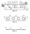
- Continuous rib formations consisting of thickened portions 36 on sheet 12, as illustrated in Figures 4 and 5, can be utilized. Ribs 36 typically are not deformable and define enclosed surface areas on which the fluid sample can be deposited.
- the sheet material enclosed is made thin such that it can be deformed as described previously to form fluid receptacles.
- the fluid may be wholly contained on sheet 12 by surface tension or partially contained on sheet 12 by mechanical means or a combination of mechanical and non-mechanical means, but not wholly contained on sheet 12 by mechanical means.
- not wholly contained is meant that the fluid is not totally enclosed by mechanical means such as a wall or walls.
- the fluid is partially contained by sheet 12 and continuous rib 36 forming bottom and side walls; however there is no top wall to wholly contain the fluid.
- Support 12 can be provided as a strip, tape or sheet which is wound on a dispenser roll and taken up by a roll at the exit of the apparatus. Conventional mechanisms for driving the rolls can be employed. Additionally, control of such drive mechanisms using microprocessor units and techniques can be conveniently applied to provide automated systems.
- the fluid volumes can be moved through the system through a disposal station to remove the fluid from the sheet by suction or otherwise. If desired, that portion of the sheet which has been used can then be cut off and disposed of in an appropriate container for safe disposal.
- elastomers to provide a flexible, liquid-impervious sheet 12 for the fluid support can be utilized.
- elastomers to provide a flexible, liquid-impervious sheet 12 for the fluid support
- latex, silicone rubber, styrene butadiene, polyurethane and the like have been found useful.
- Rigid support 14 can be manufactured from conventionally suitable materials such as metals and plastics.
- Wells 20 may be provided of varying sizes and it will be readily realized that a single fluid volume c'an be accommodated in wells of differing sizes. If the fluid support was a rigid container or the like, it would not be possible to automatically move the fluid containers across the support mechanism without individually or collectively removing the containers from the wells and then transferring them to new positions. Because sheet 12 is reversibly-deformable, relaxation of the deformation forces applied causes sheet 12 to resume substantially its original orientation, which permits sheet 12 and fluid droplets 16 to be moved to other locations.
- sheet 12 has been illustrated in combination with a separate support or substrate 18, that substrate structure could be formed directly into sheet 12 in the form of rolled edges, beads, ribs or thickened sections. Alternatively, sheet 12 can be utilized without any additional support whatsoever. However, the latter configuration may require a more complicated feeding mechanism in an automated setting because of the elastomeric nature of sheet 12.
- the first support is conveniently provided as a tape 12 in a rolled configuration which is adapted to move across the surface of support 14 by an automatic, controlled moving mechanism (not shown).
- Support 14 defines a well 20.
- the system provides a fluid dispenser 28, a reagent dispenser 30, an analyzer 32 and a disposal unit 34. Those units are located at a position above the top surface of sheet 12.
- a tape take-up means is provided to take up the used tape as it comes off the system.
- the tape or sheet can include indexing means coupled to the fluid dispenser 28 and reagent dispenser 30, individually or jointly, such that fluid and reagent dispensing is responsive to the position of the tape or sheet as indicated by the indexing means.
- a vacuum source 38 is provided and interconnected with well 20 through conduit 26 and controlled by fluid control means, for example, by values C1, C2, and C3.
- a fluid droplet is dispensed from fluid dispensing means 28 onto sheet 12. That droplet is then moved horizontally and linearly across the top of rigid support 14 to a location above well 20 where the vacuum source can be actuated.
- a reagent dispensing means 30 is provided to dispense reagent if required. Actuation of the vacuum source causes sheet 12 to spread into well 20 along the surface contours defined and form a container suitable for receipt of additional fluid. If appropriate, reagent is dispensed from dispenser 30 and the vacuum source pressure is modulated in order to promote mixing between the reagent and the sample volume. At that position or possibly at another position in the system if appropriate, analysis of the mixed fluid sample can take place by conventional analytical means 32.
- a single pipetting mechanism could be utilized to dispense both fluid sample and reagent, as necessary, and also to evacuate the mixed fluid sample upon completion of the analytical test.
- Various modifications of this illustrative system will be apparent for particular applications and instrumentation, which can include a variety of particle or substance detection systems for the detection and/or measurement of materials in fluids.
- Typical optical fibers employed will generally have a diameter of about 5 pm to about 500 pm, more usually from about 10 ⁇ m to.100 pm.
- the cone half angle of the effective sample volume will generally range from about 8° to about 60°, more usually from about 10° to about 30°.
- the effective length of the axis will also vary significantly generally ranging from about 0.5 to about 10 fiber diameters, more usually from about 1 to about 5 fiber diameters.
- a particularly useful optical fiber device is the commercially available device known as a coupler, consisting of three optical fibers joined at a junction with three terminal ports, conveniently referred to as an input port (into which excitation light is fed), a probe port (which is submerged in the sample) and a detector port.
- the fibers are joined in such a manner that substantially all light entering the input port is transmitted to the probe port.
- Light entering the probe port (as from the fluorescent emission) may be split at the conduit juncture so that a portion will travel to the input port and a second portion to the detector port.
- a dichroic mirror can be utilized at the juncture directing substantially all of the fluorescent light to the detector port.
- Such devices are available from commercial suppliers, for example: Kaptron Incorporated, Palo Alto, California.
- the excitation light may be provided by irradiating the entire sample or a major portion of the sample with excitation light.
- the excitation light may be provided by the optical fiber, so that the sample volume observed will be proportional to the volume irradiated.
- the subject invention can be utilized for determining an analyte in a sample, where the amount of analyte affects the total fluorescence or an observed pattern of fluorescence fluctuations.
- the analyte is a member of a specific binding pair consisting of ligand and its homologous receptor.
- the optical fiber is employed to receive fluorescent light from the sample volume.
- To observe fluorescence fluctuations one observes a plurality of such volumes, either by observing a single volume over an extended period of time, where particles move in and out of the volume, or scanning a plurality of volumes either simultaneously or successively, or combinations thereof.
- the percentage of volumes observed which have a predetermined difference in fluorescence from a defined level can be related to the amount of analyte in the medium.
- the particles may be uniformly fluorescent.
- the particle becomes non-fluorescent.
- fluorescent particles can be prepared having a ligand bound to the particles, which ligand is an analog of the analyte.
- Charcoal particles can be conjugated with anti-ligand (a receptor which specifically binds to a ligand).
- anti-ligand a receptor which specifically binds to a ligand.
- a heterogeneous population of fluorescent particles can come about in a number of ways. For example, one can have aggregation or agglutination of particles.
- the analyte could be a receptor or antibody, which is polyvalent in binding sites. Fluorescent particles could be conjugated with ligand, so that the polyvalent receptor would act as a bridge between particles. In this way, the greater the amount of analyte present in the medium, the larger the number of aggregates which will result.
- the particle of interest could then be chosen as a particle which is an aggregation of two or more or three or more particles.
- one could determine the size of the aggregation counting not only the total number of particles, but the number of members of each population. As the aggregation increases in size, the fluorescence of the aggregate particle will also increase, but not linearly with the increase in the number of particles in the aggregation.
- Another technique may also be illustrated by employing particle aggregation.
- non-fluoresent particles are employed, and the continuous phase is made fluorescent.
- these particles while non-fluorescent should also be substantially opaque to excitation of fluorescent light. Thus, they will create a substantial shadow, inhibiting the detection of fluorescence in a volume substantially greater than the volume of the aggregation.
- red blood cells or identifying red blood cell (RBC) antigens or the antibodies thereto can be effective by using the RBCs as fluorescence quenchers in an assay employing fluorescent particles to provide a detectable signal.
- RBC antigens normally antibodies or lectins (hereinafter “receptors") are conjugated to fluorescent particles.
- a solution of particle-conjugates is combined with red blood cells, e.g., whole blood, with an appropriate buffer. If an antigen is present on the RBCs that has a binding or determinate site specific for the receptor, the conjugated particles will bind to the RBCs which act as fluorescence quenchers.
- the determination of the presence of antibodies to a RBC antigen can be made.
- Three different techniques may be used. In one, fluorescently labeled antibodies compete with antibodies in the plasma or serum sample for antigen sites on test RBCs of a known group, with the observed cellular fluorescence decreasing with increasing amounts of antibodies against the specific antigen in the sample.
- the test RBCs may be fluorescently stained and, when combined with serum, the specific antibodies, if present, will agglutinate the fluorescent cells.
- the fluorescent bead may be conjugated with the surface antigen of interest and antibodies present in the sample act as a bridge between RBCs of known type and the antigen conjugated fluorescent particles. In this situation, decreasing fluorescence would indicate the presence of the antibodies.
- High extinction coefficients for the fluorescer are desirable and should be greatly in excess of 10,000 cm- 1 M -1 and preferably in excess of 100,000 cm-1 M -l .
- the fluorescer should also have a high quantum yield, preferably between 0.3 and 1.0.
- the fluorescer have a large Stokes shift, preferably greater than 20nm, more preferably greater than 30 nm. That is, it is preferred that the fluorescer have a substantial spread or difference in wavelengths between the absorption and emission maxima.
- fluorescers having a number of the desirable properties are the xanthene dyes, which include the fluoresceins derived from 3,6-dihydroxy-9-phenyl- xanthhydrol and rosamines and rhodamines, derived from 3,6-diamino-9-phenylxanthene.
- the rhodamines and fluoresceins have a 9-0-carboxyphenyl group, and are derivatives of 9-0-carboxy-phenylxanthene.
- Another group of fluorescent compounds are the naphthylamines, having an amino group in the alpha or beta position, usually alpha position. Included among the naphthylamino compounds are 1-dimethylaminonaphthyl--5-sulfonate, l-anilino-8-naphthalene sulfonate and 2-p-toluidinyl-6-naphthalene sulfonate.
- Other fluorescers of interest include coumarins, e.g., umbelliferone, and rare earth chelates, e.g., Tb, Eu, etc. Descriptions of fluorescers can be found in Brand, et al., Ann. Rev. Biochem., 41, 843-868 (1972) and Stryer, Science, 162, 526 (1968).
- Appropriate particles are combined with the fluorescer using standard techniques to provide fluorescent beads or microspheres.
- Fluorescent particles are commercially available.
- the fluorescent beads may be varied widely as to size and composition.
- the beads will normally be made of an inert material and include a plurality of fluorescent chromophoric functionalities.
- the beads will have a sufficient concentration of fluorescent functionalities to provide for a large signal per bead.
- Various organic polymers may be employed for the bead, e.g., polystyrene, polymethacrylate or the like or inorganic polymers, e.g., glass or combinations thereof.
- the particular choice of the polymeric composition is primarily one of convenience.
- receptors which may be antibodies, including monoclonal antibodies, or lectins, that bind either specifically or differentially to specific RBC surface antigens or antigens having the determinant site(s) of such RBC surface antigens or other antigens of interest.
- an RBC sample in a buffered aqueous solution comprising from 1-50% RBCs by volume is mixed with an approximately equal volume of the conjugated fluorescent receptor solution.
- an identical volume of fluorescent-Ab solution may be mixed with an equal volume of RBCs that lack specificity to the Ab.
- the mixed solutions are allowed to stand for up to 120 min., preferably 1-10 minutes at mild temperatures from above 0°C to about 37°C, preferably about 15-25°C. Other controls may be used.
- Free antigen or antibody could be added as an example, or the result could be compared with standard preparations of Type A, B or 0 blood or serum.
Priority Applications (1)
| Application Number | Priority Date | Filing Date | Title |
|---|---|---|---|
| AT86300487T ATE74441T1 (de) | 1985-01-25 | 1986-01-24 | Verfahren und vorrichtung zur handhabung von fluessigkeiten. |
Applications Claiming Priority (2)
| Application Number | Priority Date | Filing Date | Title |
|---|---|---|---|
| US694713 | 1985-01-25 | ||
| US06/694,713 US4676656A (en) | 1985-01-25 | 1985-01-25 | Fluid handling apparatus and method |
Publications (3)
| Publication Number | Publication Date |
|---|---|
| EP0190019A2 true EP0190019A2 (fr) | 1986-08-06 |
| EP0190019A3 EP0190019A3 (en) | 1988-09-14 |
| EP0190019B1 EP0190019B1 (fr) | 1992-04-01 |
Family
ID=24789971
Family Applications (1)
| Application Number | Title | Priority Date | Filing Date |
|---|---|---|---|
| EP86300487A Expired - Lifetime EP0190019B1 (fr) | 1985-01-25 | 1986-01-24 | Procédé et dispositif de manipulation de fluides |
Country Status (11)
| Country | Link |
|---|---|
| US (1) | US4676656A (fr) |
| EP (1) | EP0190019B1 (fr) |
| JP (1) | JP2520108B2 (fr) |
| KR (1) | KR940002466B1 (fr) |
| AT (1) | ATE74441T1 (fr) |
| AU (1) | AU587797B2 (fr) |
| CA (1) | CA1259065A (fr) |
| DE (1) | DE3684620D1 (fr) |
| DK (1) | DK38786A (fr) |
| ES (1) | ES8704635A1 (fr) |
| FI (1) | FI860344A (fr) |
Cited By (2)
| Publication number | Priority date | Publication date | Assignee | Title |
|---|---|---|---|---|
| WO2000054874A1 (fr) * | 1999-03-16 | 2000-09-21 | Fraunhofer-Gesellschaft zur Förderung der angewandten Forschung e.V. | Micromelangeur actif |
| US6755384B2 (en) | 2001-04-18 | 2004-06-29 | Hitachi Chemical Co., Ltd. | Flexible platform for liquid handling robots |
Families Citing this family (7)
| Publication number | Priority date | Publication date | Assignee | Title |
|---|---|---|---|---|
| JPH084592Y2 (ja) * | 1989-01-14 | 1996-02-07 | 株式会社堀場製作所 | 試料分析装置 |
| ES2218937T3 (es) | 1994-06-16 | 2004-11-16 | Dade Behring Marburg Gmbh | Procedimiento y dispositivo para mezclar liquidos. |
| US5795784A (en) | 1996-09-19 | 1998-08-18 | Abbott Laboratories | Method of performing a process for determining an item of interest in a sample |
| US5856194A (en) | 1996-09-19 | 1999-01-05 | Abbott Laboratories | Method for determination of item of interest in a sample |
| US7070740B1 (en) * | 2000-09-28 | 2006-07-04 | Beckman Coulter, Inc. | Method and apparatus for processing biomolecule arrays |
| US6371252B1 (en) | 2001-08-30 | 2002-04-16 | Shimano Inc. | Bicycle disc brake hub |
| US20040224425A1 (en) * | 2003-05-08 | 2004-11-11 | Gjerde Douglas T. | Biomolecule open channel solid phase extraction systems and methods |
Citations (7)
| Publication number | Priority date | Publication date | Assignee | Title |
|---|---|---|---|---|
| US2336438A (en) * | 1942-03-06 | 1943-12-07 | Scovill Manufacturing Co | Apparatus for mixing powdered materials |
| US2826076A (en) * | 1954-08-17 | 1958-03-11 | Jonathan E Boretz | Automatic sampling device |
| FR2153083A1 (fr) * | 1971-09-17 | 1973-04-27 | Vickers Ltd | |
| FR2389118A1 (fr) * | 1977-04-29 | 1978-11-24 | Chandon Investment Planning | Systeme a canaux multiples pour la manipulation de substances biologiquement actives immobilisees |
| US4349510A (en) * | 1979-07-24 | 1982-09-14 | Seppo Kolehmainen | Method and apparatus for measurement of samples by luminescence |
| JPS5887160A (ja) * | 1981-11-18 | 1983-05-24 | Dainippon Ink & Chem Inc | アクリルラツカ− |
| US4390499A (en) * | 1981-08-13 | 1983-06-28 | International Business Machines Corporation | Chemical analysis system including a test package and rotor combination |
Family Cites Families (16)
| Publication number | Priority date | Publication date | Assignee | Title |
|---|---|---|---|---|
| US2561339A (en) * | 1944-01-10 | 1951-07-24 | Chediak Alejandro | Apparatus for laboratory investigations |
| US3353325A (en) * | 1964-02-03 | 1967-11-21 | Mayer & Co Inc O | Packaging of free flowing materials |
| US3313240A (en) * | 1965-01-08 | 1967-04-11 | Itzhak E Bentov | Pump |
| US3526480A (en) * | 1966-12-15 | 1970-09-01 | Xerox Corp | Automated chemical analyzer |
| US3675488A (en) * | 1969-09-11 | 1972-07-11 | Res Foundation Of The Washingt | Apparatus for transport and storage of liquid specimens for radio-immunoassay for insulin |
| US3607090A (en) * | 1969-10-06 | 1971-09-21 | Scientific Industries | Analysis arrangment for multiple analyses of a single sample |
| BE759811A (fr) * | 1969-12-04 | 1971-06-03 | Technicon Instr | Appareil de determination automatique des vitesses de coagulation, agglutination ou floculation de liquides, et agent renforcateur de reactionutilisable avec cet appareil |
| US3712591A (en) * | 1971-11-24 | 1973-01-23 | Nasa | Zero gravity liquid mixer |
| SE381826B (sv) * | 1974-01-16 | 1975-12-22 | Duni Bila Ab | Forfarande vid kemiska arbetsoperationer samt produkt for utforande av forfarandet |
| US3944188A (en) * | 1974-05-20 | 1976-03-16 | Buchler Instruments Div. Of Searle Analytic Inc. | Concentrating vortex shaker |
| JPS5817241Y2 (ja) * | 1978-05-24 | 1983-04-07 | オリンパス光学工業株式会社 | 液体撹拌装置 |
| DE2930963C2 (de) * | 1979-07-31 | 1984-01-12 | Krämer & Grebe GmbH & Co KG Maschinen- und Modellfabrik, 3560 Biedenkopf | Verpackungsvorrichtung |
| US4264560A (en) * | 1979-12-26 | 1981-04-28 | Samuel Natelson | Clinical analytical system |
| JPS56142460A (en) * | 1980-04-08 | 1981-11-06 | Toshiba Corp | Automatic chemical analyzing device |
| US4395493A (en) * | 1981-05-14 | 1983-07-26 | Coulter Electronics, Inc. | Monolayer device using filter techniques |
| JPS5849425A (ja) * | 1981-09-19 | 1983-03-23 | Mitsuo Sohgoh Kenkyusho Kk | 混合または混練法と混合または混練装置 |
-
1985
- 1985-01-25 US US06/694,713 patent/US4676656A/en not_active Expired - Lifetime
-
1986
- 1986-01-24 DK DK38786A patent/DK38786A/da not_active Application Discontinuation
- 1986-01-24 FI FI860344A patent/FI860344A/fi not_active IP Right Cessation
- 1986-01-24 KR KR1019860000450A patent/KR940002466B1/ko not_active IP Right Cessation
- 1986-01-24 AU AU52726/86A patent/AU587797B2/en not_active Ceased
- 1986-01-24 AT AT86300487T patent/ATE74441T1/de not_active IP Right Cessation
- 1986-01-24 JP JP61014616A patent/JP2520108B2/ja not_active Expired - Lifetime
- 1986-01-24 CA CA000500311A patent/CA1259065A/fr not_active Expired
- 1986-01-24 EP EP86300487A patent/EP0190019B1/fr not_active Expired - Lifetime
- 1986-01-24 DE DE8686300487T patent/DE3684620D1/de not_active Expired - Fee Related
- 1986-01-24 ES ES551235A patent/ES8704635A1/es not_active Expired
Patent Citations (7)
| Publication number | Priority date | Publication date | Assignee | Title |
|---|---|---|---|---|
| US2336438A (en) * | 1942-03-06 | 1943-12-07 | Scovill Manufacturing Co | Apparatus for mixing powdered materials |
| US2826076A (en) * | 1954-08-17 | 1958-03-11 | Jonathan E Boretz | Automatic sampling device |
| FR2153083A1 (fr) * | 1971-09-17 | 1973-04-27 | Vickers Ltd | |
| FR2389118A1 (fr) * | 1977-04-29 | 1978-11-24 | Chandon Investment Planning | Systeme a canaux multiples pour la manipulation de substances biologiquement actives immobilisees |
| US4349510A (en) * | 1979-07-24 | 1982-09-14 | Seppo Kolehmainen | Method and apparatus for measurement of samples by luminescence |
| US4390499A (en) * | 1981-08-13 | 1983-06-28 | International Business Machines Corporation | Chemical analysis system including a test package and rotor combination |
| JPS5887160A (ja) * | 1981-11-18 | 1983-05-24 | Dainippon Ink & Chem Inc | アクリルラツカ− |
Non-Patent Citations (1)
| Title |
|---|
| PATENT ABSTRACTS OF JAPAN, vol. 7, no. 184 (P-216)[1329], 13th August 1983; & JP-A-58 087 160 (OLYMPUS KOGAKU KOGYO K.K.) 25-05-1983 * |
Cited By (2)
| Publication number | Priority date | Publication date | Assignee | Title |
|---|---|---|---|---|
| WO2000054874A1 (fr) * | 1999-03-16 | 2000-09-21 | Fraunhofer-Gesellschaft zur Förderung der angewandten Forschung e.V. | Micromelangeur actif |
| US6755384B2 (en) | 2001-04-18 | 2004-06-29 | Hitachi Chemical Co., Ltd. | Flexible platform for liquid handling robots |
Also Published As
| Publication number | Publication date |
|---|---|
| DK38786A (da) | 1986-07-26 |
| EP0190019A3 (en) | 1988-09-14 |
| FI860344A0 (fi) | 1986-01-24 |
| FI860344A (fi) | 1986-07-26 |
| ATE74441T1 (de) | 1992-04-15 |
| CA1259065A (fr) | 1989-09-05 |
| AU5272686A (en) | 1986-07-31 |
| ES551235A0 (es) | 1987-04-16 |
| DK38786D0 (da) | 1986-01-24 |
| KR940002466B1 (ko) | 1994-03-24 |
| ES8704635A1 (es) | 1987-04-16 |
| KR860005648A (ko) | 1986-08-11 |
| DE3684620D1 (de) | 1992-05-07 |
| AU587797B2 (en) | 1989-08-31 |
| JPS61204031A (ja) | 1986-09-10 |
| JP2520108B2 (ja) | 1996-07-31 |
| EP0190019B1 (fr) | 1992-04-01 |
| US4676656A (en) | 1987-06-30 |
Similar Documents
| Publication | Publication Date | Title |
|---|---|---|
| EP0764046B1 (fr) | Procede et dispositif pour melanger des liquides | |
| AU605257B2 (en) | Self-contained immunoassay element | |
| EP0425604B1 (fr) | Element d'analyse | |
| CA1310566C (fr) | Element et methode pour effectuer des bio-essais de facon precise, rapide et simple | |
| US9310286B2 (en) | Patient sample classification based upon low angle light scattering | |
| JP3535144B2 (ja) | 自動連続ランダムアクセス分析システムおよびその構成要素 | |
| JPH08506893A (ja) | サンプル用ウェルの形状と一致する担体を用いる固相イムノアッセイ | |
| EP0190019B1 (fr) | Procédé et dispositif de manipulation de fluides | |
| US8741218B2 (en) | Automatic analyzer | |
| EP0646245A1 (fr) | Appareil et procede permettant de realiser des operations individuelles impliquant la manipulation d'echantillons liquides | |
| WO1989003533A1 (fr) | Procede de detection d'especes biochimiques et appareil utilise dans ledit procede | |
| Rocks et al. | Automatic analysers in clinical biochemistry |
Legal Events
| Date | Code | Title | Description |
|---|---|---|---|
| PUAI | Public reference made under article 153(3) epc to a published international application that has entered the european phase |
Free format text: ORIGINAL CODE: 0009012 |
|
| AK | Designated contracting states |
Kind code of ref document: A2 Designated state(s): AT BE CH DE FR GB IT LI LU NL SE |
|
| PUAL | Search report despatched |
Free format text: ORIGINAL CODE: 0009013 |
|
| AK | Designated contracting states |
Kind code of ref document: A3 Designated state(s): AT BE CH DE FR GB IT LI LU NL SE |
|
| 17P | Request for examination filed |
Effective date: 19890216 |
|
| 17Q | First examination report despatched |
Effective date: 19900725 |
|
| GRAA | (expected) grant |
Free format text: ORIGINAL CODE: 0009210 |
|
| AK | Designated contracting states |
Kind code of ref document: B1 Designated state(s): AT BE CH DE FR GB IT LI LU NL SE |
|
| REF | Corresponds to: |
Ref document number: 74441 Country of ref document: AT Date of ref document: 19920415 Kind code of ref document: T |
|
| ITF | It: translation for a ep patent filed |
Owner name: JACOBACCI & PERANI S.P.A. |
|
| REF | Corresponds to: |
Ref document number: 3684620 Country of ref document: DE Date of ref document: 19920507 |
|
| ET | Fr: translation filed | ||
| PGFP | Annual fee paid to national office [announced via postgrant information from national office to epo] |
Ref country code: SE Payment date: 19921130 Year of fee payment: 8 |
|
| PGFP | Annual fee paid to national office [announced via postgrant information from national office to epo] |
Ref country code: CH Payment date: 19921203 Year of fee payment: 8 |
|
| PG25 | Lapsed in a contracting state [announced via postgrant information from national office to epo] |
Ref country code: AT Effective date: 19930124 |
|
| ITTA | It: last paid annual fee | ||
| PG25 | Lapsed in a contracting state [announced via postgrant information from national office to epo] |
Ref country code: LU Free format text: LAPSE BECAUSE OF NON-PAYMENT OF DUE FEES Effective date: 19930131 Ref country code: BE Effective date: 19930131 |
|
| PGFP | Annual fee paid to national office [announced via postgrant information from national office to epo] |
Ref country code: NL Payment date: 19930131 Year of fee payment: 8 |
|
| PLBE | No opposition filed within time limit |
Free format text: ORIGINAL CODE: 0009261 |
|
| STAA | Information on the status of an ep patent application or granted ep patent |
Free format text: STATUS: NO OPPOSITION FILED WITHIN TIME LIMIT |
|
| 26N | No opposition filed | ||
| BERE | Be: lapsed |
Owner name: SYNTEX (U.S.A.) INC. Effective date: 19930131 |
|
| PG25 | Lapsed in a contracting state [announced via postgrant information from national office to epo] |
Ref country code: SE Effective date: 19940125 |
|
| PG25 | Lapsed in a contracting state [announced via postgrant information from national office to epo] |
Ref country code: LI Effective date: 19940131 Ref country code: CH Effective date: 19940131 |
|
| PG25 | Lapsed in a contracting state [announced via postgrant information from national office to epo] |
Ref country code: NL Effective date: 19940801 |
|
| NLV4 | Nl: lapsed or anulled due to non-payment of the annual fee | ||
| REG | Reference to a national code |
Ref country code: CH Ref legal event code: PL |
|
| EUG | Se: european patent has lapsed |
Ref document number: 86300487.5 Effective date: 19940810 |
|
| PGFP | Annual fee paid to national office [announced via postgrant information from national office to epo] |
Ref country code: GB Payment date: 19981231 Year of fee payment: 14 Ref country code: FR Payment date: 19981231 Year of fee payment: 14 |
|
| PGFP | Annual fee paid to national office [announced via postgrant information from national office to epo] |
Ref country code: DE Payment date: 19990104 Year of fee payment: 14 |
|
| PG25 | Lapsed in a contracting state [announced via postgrant information from national office to epo] |
Ref country code: GB Free format text: LAPSE BECAUSE OF NON-PAYMENT OF DUE FEES Effective date: 20000124 |
|
| REG | Reference to a national code |
Ref country code: GB Ref legal event code: 732E |
|
| GBPC | Gb: european patent ceased through non-payment of renewal fee |
Effective date: 20000124 |
|
| PG25 | Lapsed in a contracting state [announced via postgrant information from national office to epo] |
Ref country code: FR Free format text: LAPSE BECAUSE OF NON-PAYMENT OF DUE FEES Effective date: 20000929 |
|
| PG25 | Lapsed in a contracting state [announced via postgrant information from national office to epo] |
Ref country code: DE Free format text: LAPSE BECAUSE OF NON-PAYMENT OF DUE FEES Effective date: 20001101 |
|
| REG | Reference to a national code |
Ref country code: FR Ref legal event code: ST |
|
| PG25 | Lapsed in a contracting state [announced via postgrant information from national office to epo] |
Ref country code: IT Free format text: LAPSE BECAUSE OF NON-PAYMENT OF DUE FEES;WARNING: LAPSES OF ITALIAN PATENTS WITH EFFECTIVE DATE BEFORE 2007 MAY HAVE OCCURRED AT ANY TIME BEFORE 2007. THE CORRECT EFFECTIVE DATE MAY BE DIFFERENT FROM THE ONE RECORDED. Effective date: 20050124 |