EP0188930A1 - Befestigungseinrichtung eines elektrischen Motors in einem Gehäuse - Google Patents
Befestigungseinrichtung eines elektrischen Motors in einem Gehäuse Download PDFInfo
- Publication number
- EP0188930A1 EP0188930A1 EP85402342A EP85402342A EP0188930A1 EP 0188930 A1 EP0188930 A1 EP 0188930A1 EP 85402342 A EP85402342 A EP 85402342A EP 85402342 A EP85402342 A EP 85402342A EP 0188930 A1 EP0188930 A1 EP 0188930A1
- Authority
- EP
- European Patent Office
- Prior art keywords
- motor
- housing
- connector
- orifice
- cage
- Prior art date
- Legal status (The legal status is an assumption and is not a legal conclusion. Google has not performed a legal analysis and makes no representation as to the accuracy of the status listed.)
- Granted
Links
- 230000005611 electricity Effects 0.000 claims 1
- 238000004378 air conditioning Methods 0.000 abstract description 2
- 238000010438 heat treatment Methods 0.000 abstract description 2
- 238000009434 installation Methods 0.000 abstract description 2
- 238000009423 ventilation Methods 0.000 abstract 1
- 238000004519 manufacturing process Methods 0.000 description 3
- 230000005540 biological transmission Effects 0.000 description 2
- 230000014759 maintenance of location Effects 0.000 description 2
- 239000004020 conductor Substances 0.000 description 1
- 230000001627 detrimental effect Effects 0.000 description 1
- 239000006185 dispersion Substances 0.000 description 1
- 239000000463 material Substances 0.000 description 1
- 230000000717 retained effect Effects 0.000 description 1
Images

Classifications
-
- H—ELECTRICITY
- H02—GENERATION; CONVERSION OR DISTRIBUTION OF ELECTRIC POWER
- H02K—DYNAMO-ELECTRIC MACHINES
- H02K5/00—Casings; Enclosures; Supports
- H02K5/04—Casings or enclosures characterised by the shape, form or construction thereof
- H02K5/22—Auxiliary parts of casings not covered by groups H02K5/06-H02K5/20, e.g. shaped to form connection boxes or terminal boxes
- H02K5/225—Terminal boxes or connection arrangements
-
- H—ELECTRICITY
- H02—GENERATION; CONVERSION OR DISTRIBUTION OF ELECTRIC POWER
- H02K—DYNAMO-ELECTRIC MACHINES
- H02K5/00—Casings; Enclosures; Supports
Definitions
- the invention relates to a device for retaining an electric motor in a housing, applicable in particular in the field of the automobile industry.
- the fans forming part of the heating and ventilating or air conditioning installations of motor vehicles comprise an impeller or a paddle wheel fixed on the shaft of an electric motor and housed in a volute or an air circulation duct presented by a housing which also forms housing and support for the electric motor.
- This housing comprises, in its part receiving the electric motor, positioning and centering means cooperating with the cage or the motor frame.
- the engine is fixed or retained in the housing by screws engaged in holes in a bottom wall of the housing and screwed into captive nuts carried by the cage or the engine frame.
- the invention particularly aims to avoid these drawbacks of the prior art, while simplifying the de'assembly and fixing operations of the electric motor in the housing.
- this motor comprising a cage or a frame for supporting the stator and guiding the motor shaft, the housing comprising centering and abutment means cooperating with said cage for positioning the motor in the housing, a wall of this housing comprising an opening for the passage of a connector suitable for being engaged on two motor power supply terminals which are fixed on said cage, characterized in that the connector comprises a projecting tab suitable for being received in a notch of a part of the motor cage and which forms, when the connector is mounted on said lugs through the orifice of the housing, a motor retaining member in The box.
- the connector used for the electrical supply of the engine which also forms the means for retaining or fixing the engine. in the housing.
- the screws used in the prior art are eliminated, as well as all the disadvantages which arose from their use.
- the connector also comprises two lateral branches forming hooks and cooperating by clipping or snap-fastening with a flange formed on said wall of the housing around the opening for passage of the connector, for fixing the connector to the housing.
- the aforementioned notch is formed in a rib of the motor cage, this rib extending in a plane passing through the axis of rotation of the motor, the orifice for the passage of the connector. is oriented radially with respect to the axis of rotation of the motor, and the abovementioned tab of the connector comprises an oblique lateral face parallel to an oblique edge of said notch.
- the aforementioned tab of the connector is advantageously formed projecting on a lateral face of the connector, the edge of the orifice for passage of the connector comprising a cutout of corresponding shape. which receives this projecting tab, so that the connector can be mounted in said orifice only one way.
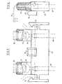
- the electric motor 10 represented in FIGS. 1 and 2 comprises, in a conventional manner, a cage or a frame 12 of plastic material supporting the stator of the motor 10 and forming, at its ends, support and guide, by means of bearings not shown. , of the shaft 14 of the motor 10 on which the rotor of this motor is fixed.
- a wheel 16 with blades or blades 18 is mounted, for example by force fitting, on one end of the shaft 14, to be driven in rotation about the axis 20 of the shaft 14 when the motor is supplied with electric current.
- the impeller 16 rotates in a duct or volute 22 for air circulation, partially shown in FIG. 1, and which is fixed to a housing 24 or is part of it.
- the housing 24 comprises a housing of substantially cylindrical shape 26 one end of which is closed by a bottom wall 28 and the other end of which is open for the introduction of the motor 10 into the housing 2.6.
- the cylindrical internal surface of this housing comprises flats 30, for example three in number, distributed at 120 ° from one another, cooperating with the external surface of a cylindrical ring 32 of the cage or frame 12 of the motor, and longitudinal ribs 34, for example three in number and distributed at 120 ° - each other, extending from the bottom wall 28 of the housing over a suitable distance, so that their end 36 opposite the bottom wall 28 forms a stop on which the end 38 of the ring 32 rests.
- the motor 10 When it is introduced into the housing 26 of the housing 24, the motor 10 is centered between the flats 30 and pushed into abutment on the ends 36 of the ribs 34.
- the cylindrical wall of the housing 26 further comprises an opening 40, radial with respect to the axis of rotation 20 of the motor, forming a passage for a connector 42 with two parallel tubular branches 44 in which are female terminals 46 (shown) in phantom line in FIGS. 3 and 4) externally connected to conductors 48 and receiving male lugs 50 fixed on the cage 12 of the motor 10, when the connector 42 is introduced into the orifice 40 of the cylindrical wall of the housing 26.
- the connector 42 also comprises lateral branches 52 forming hooks, cooperating by clipping or elastic snap-fastening with a flange 54 formed on the external face of the cylindrical wall of the housing 26, around the orifice 40 for passage of the connector 42.
- These tabs 52 make it possible to removably fix the connector to the housing 24 by elastic snap-fastening on the flange 54 at the end of the stroke for introducing the connector 42 into the orifice 40.
- the connector 42 also comprises a lug 56 formed projecting on one of its lateral faces and extending in the same direction as the branches 44 of the connector, so as to be received in a notch 58 formed in a longitudinal rib 60 of the- motor cage 12.
- This rib 60 extends in a plane passing through the axis 20 of rotation of the motor and the general orientation of the tab 56 of the connector is substantially radial, when the connector is in place on the housing 24.
- One of the front or rear faces of the tab 56 for example its rear face 62 relative to the wheel 14, is oblique, and the corresponding edge 64 of the notch 58 is parallel to this oblique face, which facilitates the 'introduction of the lug 56 in the notch 58 despite a dispersion of dimensions resulting from mass production.
- the tab 56 is formed projecting on one of the faces of the connector .42 and the orifice 40 for passage of the connector, formed in the cylindrical wall of the housing 26 of the motor in the housing 24, comprises a cutout having a shape combined with that of the tab 56 and receiving this tab when the connector is mounted on the motor.
- the connector 42 closes the orifice 40 in a substantially leaktight manner when it is mounted in place on the motor.
- the tab 56 only serves as a safety member preventing the motor from coming out of its housing of the housing, and it is not necessary for the end of this tab to be in close contact with the edges of the notch. It suffices that the tab 56 is engaged in the notch 58 so that the motor cannot be removed from the housing.
Landscapes
- Engineering & Computer Science (AREA)
- Power Engineering (AREA)
- Motor Or Generator Frames (AREA)
- Motor Or Generator Cooling System (AREA)
Applications Claiming Priority (2)
| Application Number | Priority Date | Filing Date | Title |
|---|---|---|---|
| FR8419578A FR2575342B1 (fr) | 1984-12-20 | 1984-12-20 | Dispositif de retenue d'un moteur electrique dans un boitier |
| FR8419578 | 1984-12-20 |
Publications (2)
| Publication Number | Publication Date |
|---|---|
| EP0188930A1 true EP0188930A1 (de) | 1986-07-30 |
| EP0188930B1 EP0188930B1 (de) | 1989-01-18 |
Family
ID=9310845
Family Applications (1)
| Application Number | Title | Priority Date | Filing Date |
|---|---|---|---|
| EP85402342A Expired EP0188930B1 (de) | 1984-12-20 | 1985-11-28 | Befestigungseinrichtung eines elektrischen Motors in einem Gehäuse |
Country Status (5)
| Country | Link |
|---|---|
| US (1) | US4690366A (de) |
| EP (1) | EP0188930B1 (de) |
| DE (1) | DE3567778D1 (de) |
| ES (1) | ES291171Y (de) |
| FR (1) | FR2575342B1 (de) |
Cited By (5)
| Publication number | Priority date | Publication date | Assignee | Title |
|---|---|---|---|---|
| FR2606562A1 (fr) * | 1986-11-07 | 1988-05-13 | Valeo | Support de moteur electrique, notamment pour un moteur de ventilation faisant partie d'une installation de chauffage et de ventilation d'un vehicule automobile |
| FR2618272A1 (fr) * | 1987-07-16 | 1989-01-20 | Equip Electr Moteur | Capot d'extremite detachable pour machine dynamo-electrique. |
| EP0751589A1 (de) * | 1995-06-30 | 1997-01-02 | Siemens Automotive Moteurs Electriques S.A. | Abdichtender Verbinder zur Versorgung eines Elektromotors insbesondere für das Motorgebläse einer Heizungs- oder Klimaanlage eines Fahrzeuginnenraumes |
| EP0765024A1 (de) * | 1995-09-19 | 1997-03-26 | ELCO S.p.A. | Elektrischer Motor mit einer Verbindung zu einem mit einem Verbinder ausgestatteten Kabel |
| EP0805276A2 (de) * | 1996-04-30 | 1997-11-05 | Itt Automotive Electrical Systems, Inc. | Gebläseeinheit mit integriertem Kühlluftkanal |
Families Citing this family (7)
| Publication number | Priority date | Publication date | Assignee | Title |
|---|---|---|---|---|
| US5616975A (en) * | 1994-05-11 | 1997-04-01 | Emerson Electric Co. | Integral connector and motor housing |
| US5714815A (en) * | 1995-09-05 | 1998-02-03 | Mattel, Inc. | Motor mount assembly |
| JP4404901B2 (ja) * | 2003-10-10 | 2010-01-27 | ローベルト ボツシユ ゲゼルシヤフト ミツト ベシユレンクテル ハフツング | 電動モータ |
| US7541706B2 (en) * | 2004-01-28 | 2009-06-02 | Visiocorp Patents S.A.R.L. | Electrical connector for a small electric motor |
| US9472992B2 (en) * | 2013-07-11 | 2016-10-18 | The Toro Company | Electric motor support structure and power equipment unit incorporating same |
| DE102016220641A1 (de) * | 2016-10-20 | 2018-04-26 | Continental Automotive Gmbh | Kraftstoffpumpe |
| CN213928886U (zh) * | 2020-11-11 | 2021-08-10 | 法雷奥汽车空调湖北有限公司 | 一种风机盖和风机组件 |
Citations (5)
| Publication number | Priority date | Publication date | Assignee | Title |
|---|---|---|---|---|
| FR1583878A (de) * | 1967-06-10 | 1969-12-05 | ||
| GB2002182A (en) * | 1977-07-30 | 1979-02-14 | Matsushita Electric Works Ltd | Device for fitting electric motors and for feeding power to the same |
| FR2454212A1 (fr) * | 1979-04-12 | 1980-11-07 | Ferodo Sa | Dispositif de montage d'un moteur electrique dans un boitier ou carter |
| FR2458928A1 (de) * | 1979-06-07 | 1981-01-02 | Bosch Gmbh Robert | |
| FR2536221A1 (fr) * | 1982-11-17 | 1984-05-18 | Valeo | Dispositif de support et de connexion d'un moteur electrique |
Family Cites Families (2)
| Publication number | Priority date | Publication date | Assignee | Title |
|---|---|---|---|---|
| US3622822A (en) * | 1970-03-04 | 1971-11-23 | Philips Corp | Enclosure for electric motor |
| GB1473699A (en) * | 1973-07-31 | 1977-05-18 | Mabuchi Motor Co | Motor and switch assembly |
-
1984
- 1984-12-20 FR FR8419578A patent/FR2575342B1/fr not_active Expired
-
1985
- 1985-11-28 DE DE8585402342T patent/DE3567778D1/de not_active Expired
- 1985-11-28 EP EP85402342A patent/EP0188930B1/de not_active Expired
- 1985-12-11 US US06/807,607 patent/US4690366A/en not_active Expired - Lifetime
- 1985-12-19 ES ES1985291171U patent/ES291171Y/es not_active Expired
Patent Citations (5)
| Publication number | Priority date | Publication date | Assignee | Title |
|---|---|---|---|---|
| FR1583878A (de) * | 1967-06-10 | 1969-12-05 | ||
| GB2002182A (en) * | 1977-07-30 | 1979-02-14 | Matsushita Electric Works Ltd | Device for fitting electric motors and for feeding power to the same |
| FR2454212A1 (fr) * | 1979-04-12 | 1980-11-07 | Ferodo Sa | Dispositif de montage d'un moteur electrique dans un boitier ou carter |
| FR2458928A1 (de) * | 1979-06-07 | 1981-01-02 | Bosch Gmbh Robert | |
| FR2536221A1 (fr) * | 1982-11-17 | 1984-05-18 | Valeo | Dispositif de support et de connexion d'un moteur electrique |
Cited By (7)
| Publication number | Priority date | Publication date | Assignee | Title |
|---|---|---|---|---|
| FR2606562A1 (fr) * | 1986-11-07 | 1988-05-13 | Valeo | Support de moteur electrique, notamment pour un moteur de ventilation faisant partie d'une installation de chauffage et de ventilation d'un vehicule automobile |
| FR2618272A1 (fr) * | 1987-07-16 | 1989-01-20 | Equip Electr Moteur | Capot d'extremite detachable pour machine dynamo-electrique. |
| EP0751589A1 (de) * | 1995-06-30 | 1997-01-02 | Siemens Automotive Moteurs Electriques S.A. | Abdichtender Verbinder zur Versorgung eines Elektromotors insbesondere für das Motorgebläse einer Heizungs- oder Klimaanlage eines Fahrzeuginnenraumes |
| FR2736215A1 (fr) * | 1995-06-30 | 1997-01-03 | Valeo Automotive Moteurs Elect | Connecteur etanche pour l'alimentation d'un moteur electrique, notamment dans un groupe moto-ventilateur d'un appareil de chauffage ou de climatisation d'habitacle de vehicule automobile |
| EP0765024A1 (de) * | 1995-09-19 | 1997-03-26 | ELCO S.p.A. | Elektrischer Motor mit einer Verbindung zu einem mit einem Verbinder ausgestatteten Kabel |
| EP0805276A2 (de) * | 1996-04-30 | 1997-11-05 | Itt Automotive Electrical Systems, Inc. | Gebläseeinheit mit integriertem Kühlluftkanal |
| EP0805276A3 (de) * | 1996-04-30 | 1999-05-19 | Itt Automotive Electrical Systems, Inc. | Gebläseeinheit mit integriertem Kühlluftkanal |
Also Published As
| Publication number | Publication date |
|---|---|
| ES291171U (es) | 1986-04-16 |
| FR2575342A1 (fr) | 1986-06-27 |
| US4690366A (en) | 1987-09-01 |
| FR2575342B1 (fr) | 1988-06-24 |
| ES291171Y (es) | 1986-12-16 |
| EP0188930B1 (de) | 1989-01-18 |
| DE3567778D1 (en) | 1989-02-23 |
Similar Documents
| Publication | Publication Date | Title |
|---|---|---|
| EP0186581B1 (de) | Motorgebläse, insbesondere für ein Kraftfahrzeug, fixiert mittels Unterstützungsarmen, einstückig mit der Karosserie | |
| EP0188930B1 (de) | Befestigungseinrichtung eines elektrischen Motors in einem Gehäuse | |
| FR2735854A1 (fr) | Dispositif de raccordement electrique d'un moto-ventilateur pour un echangeur de chaleur de vehicule automobile | |
| EP0085588B1 (de) | Träger für elektrisch angetriebene Maschinen, insbesondere Ventilatoren, Kompressoren, Pumpen und ähnliches | |
| FR2833917A1 (fr) | Dispositif de direction assistee a commande electrique | |
| FR3057501B1 (fr) | Motoreducteur compact | |
| EP1800917B1 (de) | Fahrzeug-Klimaanlage mit einer demontierbaren Gebläseeinheit | |
| FR2737062A1 (fr) | Dispositif pour supporter un moteur electrique entrainant une turbine, notamment pour appareil de chauffage et/ou climatisation de vehicule automobile | |
| EP3163091B1 (de) | Motoraufhängungsanordnung und entsprechende anlage zum heizen, belüften und/oder klimatisieren für kraftfahrzeug | |
| EP0292366B1 (de) | Bürstentragplatte, besonders für einen Elektromotor | |
| EP0748941B1 (de) | Gehäuse einer Motor-Gebläse Einheit für eine Heizungs- und/oder Klimaanlage eines Kraftfahrzeuges | |
| FR2536221A1 (fr) | Dispositif de support et de connexion d'un moteur electrique | |
| EP1308631A1 (de) | Motorlüfter | |
| EP0868008B1 (de) | Montageverfahren für einen elektrischen Motor | |
| FR2842656A1 (fr) | Connecteur electrique, notamment pour dispositif de chauffage de vehicule | |
| FR2708396A1 (fr) | Ensemble de mise à l'air et connecteur électrique destiné à un moteur étanche, et moteur étanche utilisant un tel ensemble. | |
| FR3038790A1 (fr) | Machine electrique tournante munie de moyens de positionnement a l'interieur d'un element hote | |
| EP3320604A1 (de) | Elektrische drehmaschine mit vorrichtung zum einstellen der winkelposition der welle | |
| FR2776050A1 (fr) | Projecteur notamment pour vehicule automobile comportant un porte-lampe a connexion simplifiee | |
| WO2017009546A1 (fr) | Machine electrique tournante munie d'un reservoir de lubrifiant pour la lubrification d'un roulement et le refroidissement de la machine | |
| FR2605685A1 (fr) | Boitier pour ventilateur axial de type plat | |
| FR2750003A1 (fr) | Module de commande, et ventilateur centrifuge associe, notamment pour installation de chauffage, ventilation et/ou climatisation de vehicule automobile | |
| FR2791192A3 (fr) | Calotte de support et fixation pour le moteur electrique d'un ventilateur | |
| FR3038792A1 (fr) | Machine electrique tournante a roulement modifie | |
| FR3107794A1 (fr) | Ensemble comportant une machine électrique et un connecteur de signal découplés |
Legal Events
| Date | Code | Title | Description |
|---|---|---|---|
| PUAI | Public reference made under article 153(3) epc to a published international application that has entered the european phase |
Free format text: ORIGINAL CODE: 0009012 |
|
| AK | Designated contracting states |
Kind code of ref document: A1 Designated state(s): DE IT |
|
| 17P | Request for examination filed |
Effective date: 19860906 |
|
| 17Q | First examination report despatched |
Effective date: 19880623 |
|
| GRAA | (expected) grant |
Free format text: ORIGINAL CODE: 0009210 |
|
| AK | Designated contracting states |
Kind code of ref document: B1 Designated state(s): DE IT |
|
| REF | Corresponds to: |
Ref document number: 3567778 Country of ref document: DE Date of ref document: 19890223 |
|
| ITF | It: translation for a ep patent filed | ||
| PLBE | No opposition filed within time limit |
Free format text: ORIGINAL CODE: 0009261 |
|
| STAA | Information on the status of an ep patent application or granted ep patent |
Free format text: STATUS: NO OPPOSITION FILED WITHIN TIME LIMIT |
|
| 26N | No opposition filed | ||
| ITTA | It: last paid annual fee | ||
| PGFP | Annual fee paid to national office [announced via postgrant information from national office to epo] |
Ref country code: DE Payment date: 20041109 Year of fee payment: 20 |