EP0188930A1 - Device for retaining an electric motor within a casing - Google Patents
Device for retaining an electric motor within a casing Download PDFInfo
- Publication number
- EP0188930A1 EP0188930A1 EP85402342A EP85402342A EP0188930A1 EP 0188930 A1 EP0188930 A1 EP 0188930A1 EP 85402342 A EP85402342 A EP 85402342A EP 85402342 A EP85402342 A EP 85402342A EP 0188930 A1 EP0188930 A1 EP 0188930A1
- Authority
- EP
- European Patent Office
- Prior art keywords
- motor
- housing
- connector
- orifice
- cage
- Prior art date
- Legal status (The legal status is an assumption and is not a legal conclusion. Google has not performed a legal analysis and makes no representation as to the accuracy of the status listed.)
- Granted
Links
- 230000005611 electricity Effects 0.000 claims 1
- 238000004378 air conditioning Methods 0.000 abstract description 2
- 238000010438 heat treatment Methods 0.000 abstract description 2
- 238000009434 installation Methods 0.000 abstract description 2
- 238000009423 ventilation Methods 0.000 abstract 1
- 238000004519 manufacturing process Methods 0.000 description 3
- 230000005540 biological transmission Effects 0.000 description 2
- 230000014759 maintenance of location Effects 0.000 description 2
- 239000004020 conductor Substances 0.000 description 1
- 230000001627 detrimental effect Effects 0.000 description 1
- 239000006185 dispersion Substances 0.000 description 1
- 239000000463 material Substances 0.000 description 1
- 230000000717 retained effect Effects 0.000 description 1
Images

Classifications
-
- H—ELECTRICITY
- H02—GENERATION; CONVERSION OR DISTRIBUTION OF ELECTRIC POWER
- H02K—DYNAMO-ELECTRIC MACHINES
- H02K5/00—Casings; Enclosures; Supports
- H02K5/04—Casings or enclosures characterised by the shape, form or construction thereof
- H02K5/22—Auxiliary parts of casings not covered by groups H02K5/06-H02K5/20, e.g. shaped to form connection boxes or terminal boxes
- H02K5/225—Terminal boxes or connection arrangements
-
- H—ELECTRICITY
- H02—GENERATION; CONVERSION OR DISTRIBUTION OF ELECTRIC POWER
- H02K—DYNAMO-ELECTRIC MACHINES
- H02K5/00—Casings; Enclosures; Supports
Definitions
- the invention relates to a device for retaining an electric motor in a housing, applicable in particular in the field of the automobile industry.
- the fans forming part of the heating and ventilating or air conditioning installations of motor vehicles comprise an impeller or a paddle wheel fixed on the shaft of an electric motor and housed in a volute or an air circulation duct presented by a housing which also forms housing and support for the electric motor.
- This housing comprises, in its part receiving the electric motor, positioning and centering means cooperating with the cage or the motor frame.
- the engine is fixed or retained in the housing by screws engaged in holes in a bottom wall of the housing and screwed into captive nuts carried by the cage or the engine frame.
- the invention particularly aims to avoid these drawbacks of the prior art, while simplifying the de'assembly and fixing operations of the electric motor in the housing.
- this motor comprising a cage or a frame for supporting the stator and guiding the motor shaft, the housing comprising centering and abutment means cooperating with said cage for positioning the motor in the housing, a wall of this housing comprising an opening for the passage of a connector suitable for being engaged on two motor power supply terminals which are fixed on said cage, characterized in that the connector comprises a projecting tab suitable for being received in a notch of a part of the motor cage and which forms, when the connector is mounted on said lugs through the orifice of the housing, a motor retaining member in The box.
- the connector used for the electrical supply of the engine which also forms the means for retaining or fixing the engine. in the housing.
- the screws used in the prior art are eliminated, as well as all the disadvantages which arose from their use.
- the connector also comprises two lateral branches forming hooks and cooperating by clipping or snap-fastening with a flange formed on said wall of the housing around the opening for passage of the connector, for fixing the connector to the housing.
- the aforementioned notch is formed in a rib of the motor cage, this rib extending in a plane passing through the axis of rotation of the motor, the orifice for the passage of the connector. is oriented radially with respect to the axis of rotation of the motor, and the abovementioned tab of the connector comprises an oblique lateral face parallel to an oblique edge of said notch.
- the aforementioned tab of the connector is advantageously formed projecting on a lateral face of the connector, the edge of the orifice for passage of the connector comprising a cutout of corresponding shape. which receives this projecting tab, so that the connector can be mounted in said orifice only one way.
- the electric motor 10 represented in FIGS. 1 and 2 comprises, in a conventional manner, a cage or a frame 12 of plastic material supporting the stator of the motor 10 and forming, at its ends, support and guide, by means of bearings not shown. , of the shaft 14 of the motor 10 on which the rotor of this motor is fixed.
- a wheel 16 with blades or blades 18 is mounted, for example by force fitting, on one end of the shaft 14, to be driven in rotation about the axis 20 of the shaft 14 when the motor is supplied with electric current.
- the impeller 16 rotates in a duct or volute 22 for air circulation, partially shown in FIG. 1, and which is fixed to a housing 24 or is part of it.
- the housing 24 comprises a housing of substantially cylindrical shape 26 one end of which is closed by a bottom wall 28 and the other end of which is open for the introduction of the motor 10 into the housing 2.6.
- the cylindrical internal surface of this housing comprises flats 30, for example three in number, distributed at 120 ° from one another, cooperating with the external surface of a cylindrical ring 32 of the cage or frame 12 of the motor, and longitudinal ribs 34, for example three in number and distributed at 120 ° - each other, extending from the bottom wall 28 of the housing over a suitable distance, so that their end 36 opposite the bottom wall 28 forms a stop on which the end 38 of the ring 32 rests.
- the motor 10 When it is introduced into the housing 26 of the housing 24, the motor 10 is centered between the flats 30 and pushed into abutment on the ends 36 of the ribs 34.
- the cylindrical wall of the housing 26 further comprises an opening 40, radial with respect to the axis of rotation 20 of the motor, forming a passage for a connector 42 with two parallel tubular branches 44 in which are female terminals 46 (shown) in phantom line in FIGS. 3 and 4) externally connected to conductors 48 and receiving male lugs 50 fixed on the cage 12 of the motor 10, when the connector 42 is introduced into the orifice 40 of the cylindrical wall of the housing 26.
- the connector 42 also comprises lateral branches 52 forming hooks, cooperating by clipping or elastic snap-fastening with a flange 54 formed on the external face of the cylindrical wall of the housing 26, around the orifice 40 for passage of the connector 42.
- These tabs 52 make it possible to removably fix the connector to the housing 24 by elastic snap-fastening on the flange 54 at the end of the stroke for introducing the connector 42 into the orifice 40.
- the connector 42 also comprises a lug 56 formed projecting on one of its lateral faces and extending in the same direction as the branches 44 of the connector, so as to be received in a notch 58 formed in a longitudinal rib 60 of the- motor cage 12.
- This rib 60 extends in a plane passing through the axis 20 of rotation of the motor and the general orientation of the tab 56 of the connector is substantially radial, when the connector is in place on the housing 24.
- One of the front or rear faces of the tab 56 for example its rear face 62 relative to the wheel 14, is oblique, and the corresponding edge 64 of the notch 58 is parallel to this oblique face, which facilitates the 'introduction of the lug 56 in the notch 58 despite a dispersion of dimensions resulting from mass production.
- the tab 56 is formed projecting on one of the faces of the connector .42 and the orifice 40 for passage of the connector, formed in the cylindrical wall of the housing 26 of the motor in the housing 24, comprises a cutout having a shape combined with that of the tab 56 and receiving this tab when the connector is mounted on the motor.
- the connector 42 closes the orifice 40 in a substantially leaktight manner when it is mounted in place on the motor.
- the tab 56 only serves as a safety member preventing the motor from coming out of its housing of the housing, and it is not necessary for the end of this tab to be in close contact with the edges of the notch. It suffices that the tab 56 is engaged in the notch 58 so that the motor cannot be removed from the housing.
Landscapes
- Engineering & Computer Science (AREA)
- Power Engineering (AREA)
- Motor Or Generator Frames (AREA)
- Motor Or Generator Cooling System (AREA)
Abstract
L'invention concerne un dispositif de retenue d'un moteur électrique (10) dans un boîtier (24) dont une paroi comprend un orifice (40) de passage d'un connecteur (42) reliant le moteur à une source d'alimentation électrique. Le connecteur (42) comprend une patte en saillie (56) reçue dans une encoche (58) de la cage (12) du moteur et formant organe de retenue du moteur dans le boîtier (24). L'invention s'applique notamment aux moteurs électriques des ventilateurs des installations de chauffage et de ventilation ou de climatisation des véhicules automobiles.The invention relates to a device for retaining an electric motor (10) in a housing (24), one wall of which comprises an orifice (40) for the passage of a connector (42) connecting the motor to an electric power source. . The connector (42) comprises a projecting tab (56) received in a notch (58) in the cage (12) of the motor and forming a motor retaining member in the housing (24). The invention applies in particular to the electric motors of fans of heating and ventilation or air conditioning installations of motor vehicles.
Description
L'invention concerne un dispositif de retenue d'un moteur électrique dans un boîtier, applicable en particulier dans le domaine de l'industrie automobile.The invention relates to a device for retaining an electric motor in a housing, applicable in particular in the field of the automobile industry.
Les ventilateurs faisant partie des installations de chauffage et de ventilation ou de climatisation de véhicules automobiles comprennent une roue à aubes ou à pales fixée sur l'arbre d'un moteur électrique et logée dans une volute ou une gaine de circulation d'air présentée par un boîtier qui forme également logement et support du moteur électrique. Ce boîtier comprend, dans sa partie recevant le moteur électrique, des moyens de positionnement et de centrage coopérant avec la cage ou le bâti du moteur. La fixation ou la retenue du moteur dans le boîtier est assurée par des vis engagées dans des trous d'une paroi de fond du boîtier et vissées dans des écrous captifs portés par la cage ou le bâti du moteur.The fans forming part of the heating and ventilating or air conditioning installations of motor vehicles comprise an impeller or a paddle wheel fixed on the shaft of an electric motor and housed in a volute or an air circulation duct presented by a housing which also forms housing and support for the electric motor. This housing comprises, in its part receiving the electric motor, positioning and centering means cooperating with the cage or the motor frame. The engine is fixed or retained in the housing by screws engaged in holes in a bottom wall of the housing and screwed into captive nuts carried by the cage or the engine frame.
Ces moyens de fixation du moteur présentent un certain nombre d'inconvénients : leur mise en oeuvre nécessite une opération particulière lors du montage du moteur dans le boîtier, et les vis de fixation transmettent, d'une part, des bruits à l'extérieur du boîtier et, d'autre part, des efforts à la cage du moteur. Comme celle-ci est en général en matière plastique, elle subit à la longue une déformation plus ou moins importante, qui est nuisible au fonctionnement correct du moteur.These engine fixing means have a certain number of drawbacks: their implementation requires a particular operation when the engine is mounted in the housing, and the fixing screws transmit, on the one hand, noise outside the housing and, on the other hand, efforts to the motor cage. As the latter is generally made of plastic, it undergoes more or less significant deformation over time, which is detrimental to the correct operation of the engine.
L'invention a notamment pour but d'éviter ces inconvénients de la technique antérieure, tout en simplifiant les opérations de'montage et de fixation du moteur électrique dans le boîtier.The invention particularly aims to avoid these drawbacks of the prior art, while simplifying the de'assembly and fixing operations of the electric motor in the housing.
Elle propose à cet effet un dispositif de retenue d'un moteur électrique dans un boîtier, ce moteur comprenant une cage ou un bâti de support du stator et de guidage de l'arbre du moteur, le boîtier comprenant des moyens de centrage et de butée coopérant avec ladite cage pour le positionnement du moteur dans le boîtier, une paroi de ce boîtier comprenant un orifice de passage d'un connecteur propre à être engagé sur deux cosses d'alimentation électrique dunoteur qui sont fixées sur ladite cage, caractérisé en ce que le connecteur comprend une patte en saillie propre à être reçue dans une encoche d'une partie de la cage du moteur et qui forme, quand le connecteur est monté sur lesdites cosses à travers l'orifice du boîtier, un organe de retenue du moteur dans le boîtier.To this end, it proposes a device for retaining an electric motor in a housing, this motor comprising a cage or a frame for supporting the stator and guiding the motor shaft, the housing comprising centering and abutment means cooperating with said cage for positioning the motor in the housing, a wall of this housing comprising an opening for the passage of a connector suitable for being engaged on two motor power supply terminals which are fixed on said cage, characterized in that the connector comprises a projecting tab suitable for being received in a notch of a part of the motor cage and which forms, when the connector is mounted on said lugs through the orifice of the housing, a motor retaining member in The box.
Ainsi, selon l'invention, c'est le connecteur utilisé pour l'alimentation électrique du moteur qui forme également les moyens de retenue ou de fixation du moteur dans le boîtier. Les vis utilisées dans la technique antérieure sont supprimées, ainsi que tous les inconvénients qui découlaient de leur utilisation.Thus, according to the invention, it is the connector used for the electrical supply of the engine which also forms the means for retaining or fixing the engine. in the housing. The screws used in the prior art are eliminated, as well as all the disadvantages which arose from their use.
Selon une autre caractéristique de l'invention, le connecteur comprend également deux branches latérales formant crochets et coopérant par clipsage ou encliquetage avec un rebord formé sur ladite paroi du boîtier autour de l'orifice de passage du connecteur, pour fixation du connecteur sur le boîtier.According to another characteristic of the invention, the connector also comprises two lateral branches forming hooks and cooperating by clipping or snap-fastening with a flange formed on said wall of the housing around the opening for passage of the connector, for fixing the connector to the housing. .
On évite ainsi un démontage accidentel du connecteur, sans pour autant compliquer les opérations d'assemblage ou de fixation du moteur dans le boîtier.This avoids accidental disassembly of the connector, without complicating the assembly or fixing of the motor in the housing.
Selon d'autres caractéristiques de l'invention, l'encoche précitée est formée dans une nervure de la cage du moteur, cette nervure s'étendant dans un plan passant par l'axe de rotation du moteur, l'orifice de passage du connecteur est orienté radialement par rapport à l'axe de rotation du moteur, et la patte précitée du connecteur comprend une face latérale oblique parallèle à un bord oblique de ladite encoche.According to other characteristics of the invention, the aforementioned notch is formed in a rib of the motor cage, this rib extending in a plane passing through the axis of rotation of the motor, the orifice for the passage of the connector. is oriented radially with respect to the axis of rotation of the motor, and the abovementioned tab of the connector comprises an oblique lateral face parallel to an oblique edge of said notch.
On peut ainsi, de façon simple et efficace, assurer un montage correct du connecteur sur le boîtier et la retenue du moteur dans le boîtier, malgré les tolérances dimensionnelles de fabrication résultant des fabrications en grande série de la cage du moteur, du connecteur et du boîtier.It is thus possible, simply and effectively, to ensure correct mounting of the connector on the housing and the retention of the motor in the housing, despite the dimensional manufacturing tolerances resulting from mass production of the motor cage, the connector and the housing.
Par ailleurs, la patte précitée du connecteur est avantageusement formée en saillie sur une face latérale du connecteur, le bord de l'orifice de passage du connecteur comprenant une découpe de forme correspondante qui reçoit cette patte en saillie, de telle sorte que le connecteur ne peut être monté dans ledit orifice que d'une seule façon.Furthermore, the aforementioned tab of the connector is advantageously formed projecting on a lateral face of the connector, the edge of the orifice for passage of the connector comprising a cutout of corresponding shape. which receives this projecting tab, so that the connector can be mounted in said orifice only one way.
Ainsi, lorsque le moteur électrique est un moteur à courant continu, on évite une inversion de son raccordement à une source de courant continu.Thus, when the electric motor is a direct current motor, a reversal of its connection to a direct current source is avoided.
Dans la description qui suit, faite à titre d'exemple, on se réfère aux dessins annexés, dans lesquels :
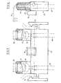
- - la figure 1 est une vue schématique en coupe axiale d'unmoteur électrique logé dans un boîtier;
- - la figure 2 est une vue schématique en coupe selon la ligne II-II de la figure 1;
- - la figure 3 est une vue en plan, à plus grande échelle, d'un connecteur selon l'invention;
- - la figure 4 est une vue de côté de ce connecteur.
- - Figure 1 is a schematic view in axial section of an electric motor housed in a housing;
- - Figure 2 is a schematic sectional view along the line II-II of Figure 1;
- - Figure 3 is a plan view, on a larger scale, of a connector according to the invention;
- - Figure 4 is a side view of this connector.
Le.moteur électrique 10 représenté dans les figures 1 et 2 comprend, de façon classique, une cage ou un bâti 12 en matière plastique supportant le stator du moteur 10 et formant, à ses extrémités, support et guidage, au moyen de paliers non représentés, de l'arbre 14 du moteur 10 sur lequel est fixé le rotor de ce moteur..The
Dans l'exemple représenté, une roue 16 à aubes ou pales 18 est montée, par exemple par emmanchement à force,sur une extrémité de l'arbre 14, pour être entraînée en rotation autour de l'axe 20 de l'arbre 14 lorsque le moteur est alimenté en courant électrique.In the example shown, a
La roue à aubes 16 tourne dans une gaine ou volute 22 de circulation d'air, représentée partiellement en figure 1, et qui est fixée sur un boîtier 24 ou fait partie de celui-ci.The
Le boîtier 24 comprend un logement de forme sensiblement cylindrique 26 dont une extrémité est fermée par une paroi de fond 28 et dont l'autre extrémité est ouverte pour l'introduction du moteur 10 dans le logement 2.6.The
La surface interne cylindrique de ce logement comprend des méplats 30, par exemple au nombre de trois, répartis à 120° les uns des autres, coopérant avec la surface externe d'une bague cylindrique 32 de la cage ou bâti 12 du moteur, et des nervures longitudinales 34, par exemple au nombre de trois et réparties à 120°-les unesdesautres,s'étendant depuis la paroi de fond 28 du boîtier sur une distance appropriée, de telle sorte que leur extrémité 36 opposée à la paroi de fond 28 forme une butée sur laquelle s'appuie l'extrémité 38 de la bague 32.The cylindrical internal surface of this housing comprises
Lors de son introduction dans le logement 26 du boîtier 24, le moteur 10 est centré entre les méplats 30 et poussé en butée sur les extrémités 36 des nervures 34.When it is introduced into the
La paroi cylindrique du logement 26 comprend en outre une ouverture 40, radiale par rapport à l'axe de rotation 20 du moteur, formant passage d'un connecteur 42 à deux branches parallèles tubulaires 44 dans lesquelles sont montées fixement des cosses femelles 46 (représentées en trait fantôme dans les figures 3 et 4) reliées extérieurement à des conducteurs 48 et recevant des cosses mâles 50 fixées sur la cage 12 du moteur 10, lorsque le connecteur 42 est introduit dans l'orifice 40 de la paroi cylindrique du logement 26.The cylindrical wall of the
Le connecteur 42 comprend également des branches latérales 52 formant crochets, coopérant par clipsage ou encliquetage élastique avec un rebord 54 formé sur la face extérieure de la paroi-cylindrique du logement 26, autour de l'orifice 40 de passage du connecteur 42. Ces pattes 52 permettent de fixer amoviblement le connecteur sur le boîtier 24 par encliquetage élastique sur le rebord 54 à laffin de la course d'introduction du connecteur 42 dans l'orifice 40.The
Le connecteur 42 comprend encore une patte 56 formée en saillie sur une de ses faces latérales et s'étendant dans la même direction que les branches 44 du connecteur,de façon à être reçue dans une encoche 58 formée dans une nervure longitudinale 60 de la-cage 12 du moteur. Cette nervure 60 s'étend dans un plan passant par l'axe 20 de rotation du moteur et l'orientation générale de la patte 56 du connecteur est sensiblement radiale, quand le connecteur est en place sur le boîtier 24.The
L'une des faces avant ou arrière de la patte 56, par exemple sa face arrière 62 par rapport à la roue 14, est oblique, et le bord correspondant 64 de l'encoche 58 est parallèle à cette face oblique, ce qui facilite l'introduction de la patte 56 dans l'encoche 58 malgré une dispersion de cotes résultant de fabrications en grande série.One of the front or rear faces of the
Comme on le voit dans les figures 3 et 4, la patte 56 est formée en saillie sur l'une des faces du connecteur .42 et l'orifice 40 de passage du connecteur,formé dans la paroi cylindrique du logement 26 du moteur dans le boîtier 24, comprend une découpe ayant une forme conjuguée de celle de la patte 56 et recevant cette patte lorsque le connecteur est monté sur le moteur. Ainsi, dans le cas d'un moteur à courant continu, on assure que les cosses 50 du moteur sont reliées de façon correcte aux bornes positive et négative d'une source de courant continu, par l'intermédiaire du con- .necteur, et que le moteur ne peut être raccordé à l'envers à cette source de courant.As seen in Figures 3 and 4, the
De préférence, le connecteur 42 ferme de façon sensiblement étanche l'orifice 40 lorsqu'il est monté en place sur le moteur.Preferably, the
Lorsque le moteur 10 est monté par emmanchement à force dans le logement 26 du boîtier 24, et positionné par butée de la bague 32 sur l'extrémité 36 des nervures 34, il suffit d'introduire le connecteur 42 dans l'orifice de passage 40 pour, d'une part, relier le moteur à sa source d'alimentation électrique et, d'autre part, assurer la retenue du moteur dans le boîtier 24, en raison de l'engagement de la patte 56 dans l'encoche 58 précitée. Cette retenue du moteur dans le boîtier 24 s'effectue sans transmission d'une contrainte de déformation à la cage 12 du moteur. En outre, la retenue du moteur dans le boîtier 24 par l'intermédiaire du connecteur 42 évite la transmission de bruit à l'extérieur du boîtier, qui se produisait dans la technique antérieure. En général, la patte 56 sert uniquement d'organe de sécurité empêchant que le moteur sorte de son logement du boîtier, et il n'est pas nécessaire que l'extrémité de cette patte soit en contact étroit avec les bords de l'encoche. Il suffit que la patte 56 soit engagée dans l'encoche 58 pour que le moteur ne puisse être extrait du boîtier.When the
Claims (8)
Applications Claiming Priority (2)
| Application Number | Priority Date | Filing Date | Title |
|---|---|---|---|
| FR8419578A FR2575342B1 (en) | 1984-12-20 | 1984-12-20 | DEVICE FOR RETAINING AN ELECTRIC MOTOR IN A HOUSING |
| FR8419578 | 1984-12-20 |
Publications (2)
| Publication Number | Publication Date |
|---|---|
| EP0188930A1 true EP0188930A1 (en) | 1986-07-30 |
| EP0188930B1 EP0188930B1 (en) | 1989-01-18 |
Family
ID=9310845
Family Applications (1)
| Application Number | Title | Priority Date | Filing Date |
|---|---|---|---|
| EP85402342A Expired EP0188930B1 (en) | 1984-12-20 | 1985-11-28 | Device for retaining an electric motor within a casing |
Country Status (5)
| Country | Link |
|---|---|
| US (1) | US4690366A (en) |
| EP (1) | EP0188930B1 (en) |
| DE (1) | DE3567778D1 (en) |
| ES (1) | ES291171Y (en) |
| FR (1) | FR2575342B1 (en) |
Cited By (5)
| Publication number | Priority date | Publication date | Assignee | Title |
|---|---|---|---|---|
| FR2606562A1 (en) * | 1986-11-07 | 1988-05-13 | Valeo | Electric motor support, especially for a ventilating motor forming part of a heating and ventilating installation of a motor vehicle |
| FR2618272A1 (en) * | 1987-07-16 | 1989-01-20 | Equip Electr Moteur | Detachable end shroud for dynamo-electric machine |
| EP0751589A1 (en) * | 1995-06-30 | 1997-01-02 | Siemens Automotive Moteurs Electriques S.A. | Sealed connector for electromotor supply, especially for a motor ventilator unit of a heating or air-conditioning device for the interior of a vehicle |
| EP0765024A1 (en) * | 1995-09-19 | 1997-03-26 | ELCO S.p.A. | Electric motor equipped for connection to a cable provided with a connector |
| EP0805276A2 (en) * | 1996-04-30 | 1997-11-05 | Itt Automotive Electrical Systems, Inc. | Blower assembly having integral air flow cooling duct |
Families Citing this family (7)
| Publication number | Priority date | Publication date | Assignee | Title |
|---|---|---|---|---|
| US5616975A (en) * | 1994-05-11 | 1997-04-01 | Emerson Electric Co. | Integral connector and motor housing |
| US5714815A (en) * | 1995-09-05 | 1998-02-03 | Mattel, Inc. | Motor mount assembly |
| CN1864314B (en) * | 2003-10-10 | 2010-11-03 | 罗伯特·博世有限公司 | Electric motor |
| US7541706B2 (en) * | 2004-01-28 | 2009-06-02 | Visiocorp Patents S.A.R.L. | Electrical connector for a small electric motor |
| US9472992B2 (en) * | 2013-07-11 | 2016-10-18 | The Toro Company | Electric motor support structure and power equipment unit incorporating same |
| DE102016220641A1 (en) * | 2016-10-20 | 2018-04-26 | Continental Automotive Gmbh | Fuel pump |
| CN213928886U (en) * | 2020-11-11 | 2021-08-10 | 法雷奥汽车空调湖北有限公司 | Fan cover and fan assembly |
Citations (5)
| Publication number | Priority date | Publication date | Assignee | Title |
|---|---|---|---|---|
| FR1583878A (en) * | 1967-06-10 | 1969-12-05 | ||
| GB2002182A (en) * | 1977-07-30 | 1979-02-14 | Matsushita Electric Works Ltd | Device for fitting electric motors and for feeding power to the same |
| FR2454212A1 (en) * | 1979-04-12 | 1980-11-07 | Ferodo Sa | Mounting frame for vehicle electric motors - has sprung plastic sleeve positioning motor in its housing |
| FR2458928A1 (en) * | 1979-06-07 | 1981-01-02 | Bosch Gmbh Robert | |
| FR2536221A1 (en) * | 1982-11-17 | 1984-05-18 | Valeo | Electrical fan housing for car air conditioning |
Family Cites Families (2)
| Publication number | Priority date | Publication date | Assignee | Title |
|---|---|---|---|---|
| US3622822A (en) * | 1970-03-04 | 1971-11-23 | Philips Corp | Enclosure for electric motor |
| GB1473699A (en) * | 1973-07-31 | 1977-05-18 | Mabuchi Motor Co | Motor and switch assembly |
-
1984
- 1984-12-20 FR FR8419578A patent/FR2575342B1/en not_active Expired
-
1985
- 1985-11-28 DE DE8585402342T patent/DE3567778D1/en not_active Expired
- 1985-11-28 EP EP85402342A patent/EP0188930B1/en not_active Expired
- 1985-12-11 US US06/807,607 patent/US4690366A/en not_active Expired - Lifetime
- 1985-12-19 ES ES1985291171U patent/ES291171Y/en not_active Expired
Patent Citations (5)
| Publication number | Priority date | Publication date | Assignee | Title |
|---|---|---|---|---|
| FR1583878A (en) * | 1967-06-10 | 1969-12-05 | ||
| GB2002182A (en) * | 1977-07-30 | 1979-02-14 | Matsushita Electric Works Ltd | Device for fitting electric motors and for feeding power to the same |
| FR2454212A1 (en) * | 1979-04-12 | 1980-11-07 | Ferodo Sa | Mounting frame for vehicle electric motors - has sprung plastic sleeve positioning motor in its housing |
| FR2458928A1 (en) * | 1979-06-07 | 1981-01-02 | Bosch Gmbh Robert | |
| FR2536221A1 (en) * | 1982-11-17 | 1984-05-18 | Valeo | Electrical fan housing for car air conditioning |
Cited By (7)
| Publication number | Priority date | Publication date | Assignee | Title |
|---|---|---|---|---|
| FR2606562A1 (en) * | 1986-11-07 | 1988-05-13 | Valeo | Electric motor support, especially for a ventilating motor forming part of a heating and ventilating installation of a motor vehicle |
| FR2618272A1 (en) * | 1987-07-16 | 1989-01-20 | Equip Electr Moteur | Detachable end shroud for dynamo-electric machine |
| EP0751589A1 (en) * | 1995-06-30 | 1997-01-02 | Siemens Automotive Moteurs Electriques S.A. | Sealed connector for electromotor supply, especially for a motor ventilator unit of a heating or air-conditioning device for the interior of a vehicle |
| FR2736215A1 (en) * | 1995-06-30 | 1997-01-03 | Valeo Automotive Moteurs Elect | WATERPROOF CONNECTOR FOR THE POWER SUPPLY OF AN ELECTRIC MOTOR, PARTICULARLY IN A MOTOR-FAN GROUP OF A HEATER OR AIR CONDITIONING APPARATUS OF A MOTOR VEHICLE |
| EP0765024A1 (en) * | 1995-09-19 | 1997-03-26 | ELCO S.p.A. | Electric motor equipped for connection to a cable provided with a connector |
| EP0805276A2 (en) * | 1996-04-30 | 1997-11-05 | Itt Automotive Electrical Systems, Inc. | Blower assembly having integral air flow cooling duct |
| EP0805276A3 (en) * | 1996-04-30 | 1999-05-19 | Itt Automotive Electrical Systems, Inc. | Blower assembly having integral air flow cooling duct |
Also Published As
| Publication number | Publication date |
|---|---|
| ES291171Y (en) | 1986-12-16 |
| FR2575342B1 (en) | 1988-06-24 |
| DE3567778D1 (en) | 1989-02-23 |
| ES291171U (en) | 1986-04-16 |
| EP0188930B1 (en) | 1989-01-18 |
| US4690366A (en) | 1987-09-01 |
| FR2575342A1 (en) | 1986-06-27 |
Similar Documents
| Publication | Publication Date | Title |
|---|---|---|
| EP0186581B1 (en) | Engine fan, especially for a motor vehicle, fixed to supporting arms integral with the car body | |
| EP0188930B1 (en) | Device for retaining an electric motor within a casing | |
| FR2735854A1 (en) | DEVICE FOR ELECTRICALLY CONNECTING A MOTOR-FAN FOR A MOTOR VEHICLE HEAT EXCHANGER | |
| EP0085588B1 (en) | Support for electric motor mechanisms such as ventilators, compressors, pumps and the like | |
| FR2833917A1 (en) | Electrically-powered steering device for automotive vehicle, has control substrate to which motor power terminals, torque detector terminals and motor driver terminals are extended, which is penetrated by steering shaft | |
| FR3057501A1 (en) | COMPACT MOTOREDUCER | |
| EP1800917B1 (en) | Vehicle air conditioner comprising a demountable blower unit | |
| EP3163091B1 (en) | Engine mount assembly and corresponding heating, ventilation and/or air-conditioning system for a motor vehicle | |
| EP0292366B1 (en) | Brush holder plate, particularly for an electric engine | |
| FR2772844A1 (en) | Air circulation fan unit for motor vehicle cooling | |
| EP0748941B1 (en) | Housing of a motor-blower combination for a heating and/or ventilating apparatus of a motor vehicle | |
| FR2536221A1 (en) | Electrical fan housing for car air conditioning | |
| EP1308631A1 (en) | Motor fan unit | |
| EP0868008B1 (en) | Method of assembling an electric motor | |
| WO2004010539A1 (en) | Electrical connector, in particular for vehicle heating device | |
| EP3320604A1 (en) | Rotary electric machine equipped with a means of adjusting the angular position of the shaft | |
| EP3320601A1 (en) | Rotary electric machine provided with a centring pin | |
| FR2666123A1 (en) | ELECTRIC FUEL PUMP. | |
| FR2776050A1 (en) | PROJECTOR, PARTICULARLY FOR A MOTOR VEHICLE COMPRISING A LAMP HOLDER WITH SIMPLIFIED CONNECTION | |
| FR2605685A1 (en) | Casing for an axial fan of the flat type | |
| FR2750003A1 (en) | CONTROL MODULE AND ASSOCIATED CENTRIFUGAL FAN, PARTICULARLY FOR MOTOR VEHICLE HEATING, VENTILATION AND / OR AIR CONDITIONING | |
| EP3320602A1 (en) | Rotary electric machine provided with a reservoir of lubricant for lubricating a rolling bearing and for cooling the machine | |
| WO2021170508A1 (en) | Assembly comprising an electric machine and a signal connector which are uncoupled | |
| FR2877419A1 (en) | Adapter ring for electric fan unit of motor vehicle`s heating and/or air-conditioning installation, has annular surface pierced with opening and extended outwards by conduit forming tunnel to guide electric connector towards electric motor | |
| WO2003038285A1 (en) | Motor fan system |
Legal Events
| Date | Code | Title | Description |
|---|---|---|---|
| PUAI | Public reference made under article 153(3) epc to a published international application that has entered the european phase |
Free format text: ORIGINAL CODE: 0009012 |
|
| AK | Designated contracting states |
Kind code of ref document: A1 Designated state(s): DE IT |
|
| 17P | Request for examination filed |
Effective date: 19860906 |
|
| 17Q | First examination report despatched |
Effective date: 19880623 |
|
| GRAA | (expected) grant |
Free format text: ORIGINAL CODE: 0009210 |
|
| AK | Designated contracting states |
Kind code of ref document: B1 Designated state(s): DE IT |
|
| REF | Corresponds to: |
Ref document number: 3567778 Country of ref document: DE Date of ref document: 19890223 |
|
| ITF | It: translation for a ep patent filed | ||
| PLBE | No opposition filed within time limit |
Free format text: ORIGINAL CODE: 0009261 |
|
| STAA | Information on the status of an ep patent application or granted ep patent |
Free format text: STATUS: NO OPPOSITION FILED WITHIN TIME LIMIT |
|
| 26N | No opposition filed | ||
| ITTA | It: last paid annual fee | ||
| PGFP | Annual fee paid to national office [announced via postgrant information from national office to epo] |
Ref country code: DE Payment date: 20041109 Year of fee payment: 20 |