EP0187508A2 - Brenner zur Hochtemperaturoberflächenverbrennung - Google Patents
Brenner zur Hochtemperaturoberflächenverbrennung Download PDFInfo
- Publication number
- EP0187508A2 EP0187508A2 EP85309303A EP85309303A EP0187508A2 EP 0187508 A2 EP0187508 A2 EP 0187508A2 EP 85309303 A EP85309303 A EP 85309303A EP 85309303 A EP85309303 A EP 85309303A EP 0187508 A2 EP0187508 A2 EP 0187508A2
- Authority
- EP
- European Patent Office
- Prior art keywords
- burner
- combustion
- porous body
- mixed gas
- ceramic porous
- Prior art date
- Legal status (The legal status is an assumption and is not a legal conclusion. Google has not performed a legal analysis and makes no representation as to the accuracy of the status listed.)
- Granted
Links
- 238000002485 combustion reaction Methods 0.000 title claims abstract description 82
- 239000000919 ceramic Substances 0.000 claims abstract description 42
- 239000011148 porous material Substances 0.000 claims abstract description 34
- 239000000446 fuel Substances 0.000 claims abstract description 20
- 239000000835 fiber Substances 0.000 claims description 5
- 239000012784 inorganic fiber Substances 0.000 claims description 4
- 239000007789 gas Substances 0.000 description 24
- 239000002737 fuel gas Substances 0.000 description 10
- 239000000428 dust Substances 0.000 description 8
- 239000004071 soot Substances 0.000 description 6
- 230000035939 shock Effects 0.000 description 5
- PNEYBMLMFCGWSK-UHFFFAOYSA-N aluminium oxide Inorganic materials [O-2].[O-2].[O-2].[Al+3].[Al+3] PNEYBMLMFCGWSK-UHFFFAOYSA-N 0.000 description 4
- 238000000465 moulding Methods 0.000 description 4
- 229910052593 corundum Inorganic materials 0.000 description 3
- 238000010304 firing Methods 0.000 description 3
- 229910001845 yogo sapphire Inorganic materials 0.000 description 3
- ATUOYWHBWRKTHZ-UHFFFAOYSA-N Propane Chemical compound CCC ATUOYWHBWRKTHZ-UHFFFAOYSA-N 0.000 description 2
- 230000035699 permeability Effects 0.000 description 2
- 239000000843 powder Substances 0.000 description 2
- 230000005855 radiation Effects 0.000 description 2
- 230000000630 rising effect Effects 0.000 description 2
- 239000002002 slurry Substances 0.000 description 2
- 229920005830 Polyurethane Foam Polymers 0.000 description 1
- 239000011230 binding agent Substances 0.000 description 1
- 230000008033 biological extinction Effects 0.000 description 1
- 230000015556 catabolic process Effects 0.000 description 1
- 239000003245 coal Substances 0.000 description 1
- 239000000571 coke Substances 0.000 description 1
- 230000000052 comparative effect Effects 0.000 description 1
- 238000010276 construction Methods 0.000 description 1
- 229910052878 cordierite Inorganic materials 0.000 description 1
- 230000007797 corrosion Effects 0.000 description 1
- 238000005260 corrosion Methods 0.000 description 1
- JSKIRARMQDRGJZ-UHFFFAOYSA-N dimagnesium dioxido-bis[(1-oxido-3-oxo-2,4,6,8,9-pentaoxa-1,3-disila-5,7-dialuminabicyclo[3.3.1]nonan-7-yl)oxy]silane Chemical compound [Mg++].[Mg++].[O-][Si]([O-])(O[Al]1O[Al]2O[Si](=O)O[Si]([O-])(O1)O2)O[Al]1O[Al]2O[Si](=O)O[Si]([O-])(O1)O2 JSKIRARMQDRGJZ-UHFFFAOYSA-N 0.000 description 1
- KZHJGOXRZJKJNY-UHFFFAOYSA-N dioxosilane;oxo(oxoalumanyloxy)alumane Chemical compound O=[Si]=O.O=[Si]=O.O=[Al]O[Al]=O.O=[Al]O[Al]=O.O=[Al]O[Al]=O KZHJGOXRZJKJNY-UHFFFAOYSA-N 0.000 description 1
- 238000001035 drying Methods 0.000 description 1
- 230000000694 effects Effects 0.000 description 1
- 229910052647 feldspar group Inorganic materials 0.000 description 1
- 238000005187 foaming Methods 0.000 description 1
- 238000002309 gasification Methods 0.000 description 1
- 238000010438 heat treatment Methods 0.000 description 1
- 238000002347 injection Methods 0.000 description 1
- 239000007924 injection Substances 0.000 description 1
- 239000002184 metal Substances 0.000 description 1
- 238000000034 method Methods 0.000 description 1
- 238000002156 mixing Methods 0.000 description 1
- 239000000203 mixture Substances 0.000 description 1
- 229910003465 moissanite Inorganic materials 0.000 description 1
- 229910052863 mullite Inorganic materials 0.000 description 1
- 230000002093 peripheral effect Effects 0.000 description 1
- 239000011496 polyurethane foam Substances 0.000 description 1
- 239000001294 propane Substances 0.000 description 1
- 239000002994 raw material Substances 0.000 description 1
- 229910010271 silicon carbide Inorganic materials 0.000 description 1
- 238000005245 sintering Methods 0.000 description 1
- 239000000243 solution Substances 0.000 description 1
Images

Classifications
-
- F—MECHANICAL ENGINEERING; LIGHTING; HEATING; WEAPONS; BLASTING
- F23—COMBUSTION APPARATUS; COMBUSTION PROCESSES
- F23D—BURNERS
- F23D14/00—Burners for combustion of a gas, e.g. of a gas stored under pressure as a liquid
- F23D14/12—Radiant burners
-
- F—MECHANICAL ENGINEERING; LIGHTING; HEATING; WEAPONS; BLASTING
- F23—COMBUSTION APPARATUS; COMBUSTION PROCESSES
- F23D—BURNERS
- F23D2203/00—Gaseous fuel burners
- F23D2203/10—Flame diffusing means
- F23D2203/102—Flame diffusing means using perforated plates
-
- F—MECHANICAL ENGINEERING; LIGHTING; HEATING; WEAPONS; BLASTING
- F23—COMBUSTION APPARATUS; COMBUSTION PROCESSES
- F23D—BURNERS
- F23D2203/00—Gaseous fuel burners
- F23D2203/10—Flame diffusing means
- F23D2203/105—Porous plates
Definitions
- This invention relates to a high temperature surface combustion burner having a uniform surface combustion temperature and strong thermal shock used for industrial furnaces and the like.
- This invention further relates to a surface combustion burner having a wide combustion range and excellent durability.
- the surface temperature of an intermediate portion between throughholes is low, and it has further such shortcomings that the ceramic plate is liable to breakdown by a thermal shock at the time of igniting the burner, that it takes time to make the surface of the ceramic plate after ignition the red heat condition, that since thermal conductivity of the ceramic plate is high, when the surface combustion temperature is raised to more than 900°C, the temperature in the vicinity of throughholes on the rear of the ceramic plate is raised to ignite fuel gas and to incur the danger of back fire, that notwithstanding the desirable surface temperature of more than 900°C in order to improve radiation efficiency, the surface temperature should be suppressed to less than about 900°C.
- Japanese Patent Laid-open No. 56-130,524 there is partially used a surface combustion burner for burning fuel gas on the surface of a metal fiber or ceramic fiber, but this surface combustion burner is advantageous in short rising time from ignition to the red heat condition and easy processing though, it is disadvantageous for obtaining large radiation efficiency by raising the surface temperature owing to small corrosion resistance at high temperature.
- a burner comprising a non-permeable ceramic plate provided with a number of throughholes is widely used, but in this type of burner, the combustion is carried out on the surface of the throughholes only, so that the temperature distribution between portions where no throughhole is existent, tends to be non-uniform, and the thermal conductivity of the ceramic plate is high, so that the temperature in the vicinity of the throughholes on the surface of the ceramic plate is raised to cause back fire, and in case of accelerating the injection speed of a mixed gas, a blow-off phenomenon is liable to occur, so that a high intensity combustion cannot be attained.
- An object of the present invention is to obviate the above-described shortcomings of the prior art surface combustion burners and to provide a high temperature surface combustion burner which can make a surface temperature uniformly high such as more than 900°C, is durable against a high thermal shock, and is ready to be red heat immediately after ignition.
- Another object of the invention is to obviate the above shortcomings of the prior surface combustion burner and to provide a surface combustion burner which can stably continue the combustion within the wide load range without causing any blow-off or back fire, and also continue the combustion for a period of time without clogging a burner element by soot and dust contained in fuel gas or combustion air.
- the invention relates to a high temperature surface combustion burner, comprises a burner head having an air fuel mixed gas supply inlet, a burner plate secured to said burner head, said burner element consisting of a ceramic porous body having pores sufficiently communicated from inside to outside for diffusing an air fuel mixed gas, wherein the burner plate is made of a ceramic porous body having more than 30% by volume of pores of 25 to 500 ⁇ in mean pore diameter; and a plurality of throughholes each having hydraulic diameter of 0.05-5.0 mm and substantially vertically-extending with respect to the combustion surface and provided in said burner element at intervals of 2 to 30 mm.
- 1 is a burner head
- 2 is an air fuel mixed gas supply inlet
- 3 is a burner plate
- 4 is a number of throughhole
- 5 is a burner element
- 6- is a porous ceramic body
- 7 is a throughhole.
- 1 is a burner head provided with an air fuel mixed gas supply inlet 2
- 3 is a burner plate fixed to an opening of the burner head 1.
- the burner plate 3 is made by a ceramic porous body such as Al 2 O 3 group, Zr0 2 group, feldspar group and the like having more than 30% by volume of pores of 25 to 500 ⁇ m in mean pore diameter provided with a number of throughholes 4 having a hydraulic diameter of 0.05 to 5.0 mm at intervals of 2 to 30 mm, which, for example, can be obtained by mixing these ceramic powders with glaze and an inorganic binder, molding the mixture, firing and sintering the molded article at a temperature of more than 1,000°C.
- the strength of the ceramic porous body is improved and the thermal shock resistance becomes excellent.
- a heat-resisting inorganic fiber such as SiO 2 -Al 2 O 3 ceramic fiber, Al 2 O 3 ceramic fiber and the like
- the method of providing throughholes 4 in the ceramic porous body may be attained by molding with a mold at the time of molding or by providing with intervals by a drill after molding.
- the reason why the hydraulic diameter of the throughhole 4 is made 0.05 to 5.0 mm is because less than 0.05 mm can hardly generate main combustion at the throughhole portion and the combustion becomes incomplete, and more than 5.0 mm generates a blow through phenomenon of combustion flames and the combustion becomes non-uniform.
- the reason why the interval of the throughhole 4 is made 2 to 30 mm is because less than 2 mm lowers the strength of the burner plane and more than 30 mm cannot make surface temperature uniform. Further, less than 2% of the heat-resisting inorganic fiber is insufficient in addition effect and more than 50% thereof lowers strength, so that the range of 2 to 50% is preferable.
- the burner plate 3 is a convexly curved plate and the same as the first embodiment shown in Fig. 1, except that a combustion area is increased and the high intensity combustion is obtained and that the heat transfer direction of a heat amount generated is different.
- the drawing does not show a concavely curved burner plate 3, but the same is applied to such plate.
- the fuel gas when the fuel gas is supplied to the inside of a burner head 1, the fuel gas is passed through and combusted on the surface of a burner plate 3 through a number of throughholes 4 having a hydraulic diameter of 0.05 to 5.0 mm, preferably 0.5 to 2.0 mm, provided in the burner plate 3 at intervals in the same manner as in the prior Schwank burner, but the burner plate 3 of the present invention is a ceramic porous body having more than 30% by volume of pores of 25 to 500 p in mean pore diameter, so that the fuel gas exudes and combusts even at the intermediate portion of the throughhole 4 through these pores, and a uniform surface temperature can be obtained.
- the burner plate 3 of the present invention is porous and has small inner thermal conductivity, so that there is no possibility of back firing, even if the surface temperature is raised to 900 to 1,200°C, and as a result, the stable combustion can be obtained by making the surface combustion intensity large and the surface of the burner plate 3 can be made red heat immediately after ignition.
- the invention comprises a ceramic porous body having more than 30% by volume of pores of 25 to 500 ⁇ in means pore diameter and a number of throughholes each having hydraulic diameter of 0.05-5.0 mm and substantially vertically extending with respect to the combustion surface and provided in said burner plate at intervals of 2 to 30 mm, wherein the gas fuel exuded through these pores combusts even at the intermediate portion of the throughhole, so that the surface temperature is made uniform and even if the surface temperature is raised to more than 900°C, the stable combustion can be carried out without any danger of back fire.
- the high temperature surface combustion burner according to the invention is short in rising time from ignition to the red heat condition and excellent in thermal shock resistance, so that the invention is extremely useful in practical value as a solution of disadvantages inherent to the prior surface combustion burner.
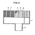
- Fig. 3 shows another embodiment of the present invention.
- reference numeral 1 is a burner head provided with a mixed gas supply inlet 2 for supplying an air fuel mixed gas
- 5 is a burner element fixed to an opening portion of the burner head 1.
- Said burner element 5 is made by providing a number of throughholes 7 having a uniform diameter in a ceramic porous body 6 having pores sufficiently communicated from inside to outside for diffusing the mixed gas at intervals.
- This ceramic porous body 6 is obtained, for example, by foaming soft polyurethane foam, removing a foamed film, impregnating in a slurry of ceramic powder such as cordierite, alumina, mullite, SiC and the like, removing the excessive slurry, drying and firing, in which a mean pore diameter of the communicated pore is 0.5 to 5.0 mm-and its total volume is 75 to 95% by volume. If the mean pore diameter of the ceramic porous body is less than 0.5 mm, the clogging is liable to generate, while if it exceeds 5.0 mm, the .strength is lowered.
- the number of throughholes 7 provided in the burner element 5 at suitable intervals have a hydraulic diameter, that is, the value of (throughhole cross-sectional area x 4/throughhole inner peripheral length) of 0.05 to 5.0 mm and the interval of 2 to 30 mm.
- the hydraulic diameter of the throughhole 7 is less than 0.05 mm, the burner element is clogged by dirt and dust contained in fuel gas or combustion air so that no stable combustion is obtained.
- the relation between a diameter (a) of the throughhole 7 and a diameter (d) of the pore of the ceramic body 6 is preferably ae2d for high intensity combustion.
- the mixed gas is injected from a number of throughhole 7 provided in a burner element 5 fixed to an opening of a burner head 1 and burns, and since the burner element 5 consists of a ceramic porous body having pores sufficiently communicated from inside to outside for diffusing the mixed gas, a large amount of the mixed gas is injected from the surface of the burner element 5 between the throughhole 7 and the throughhole 7 and burns.
- the throughholes 7 have a uniform bore shape, so that main combustion is carried out at the portion of this throughhole 7 and the high intensity of combustion becomes possible, while the soot and dust in air fuel mixed gas for combustion pass through said throughholes, so that the stable combustion is possible without any clogging.
- the intermediate portion between the throughhole 7 and the throughhole 7 of the burner element becomes red heat, and a large amount of mixed gas is burnt at this intermediate portion, so that a stable continuous flame is formed by a long flame at the periphery portion of the throughhole 7 and a short flame at the intermediate portion, and it becomes possible to uniformalize the surface combustion temperature.
- the burner element of the invention further has large porosity and considerably low thermal conductivity, so that there is no possibility of causing any back fire.
- the surface combustion burner of the invention is further extremely small in pressure loss of the burner element, and extremely small in increase of pressure loss in operation for a long period of time.
- three kinds of surface combustion burner were formed as shown in No. 1 to No. 3 of Tables 5 and 6, and a combustion test was conducted together with the surface combustion burner as a comparative example shown in No. 4. As shown in each Table, the surface combustion burner of the invention has an extremely wide combustion load range, is low in pressure loss and small in time change.
- the invention can prevent any flame blow-off and back fire by thermal conductivity of burner element and continue the stable combustion within a wide combustion load range from low intensity combustion to high intensity combustion, and further can be used for a long period of time with low pressure loss without clogging by dirt and dust in air fuel mixed gas, so that the invention has an extremely large practical value by solving the problems of the prior surface combustion burners.
Landscapes
- Engineering & Computer Science (AREA)
- Chemical & Material Sciences (AREA)
- Combustion & Propulsion (AREA)
- Mechanical Engineering (AREA)
- General Engineering & Computer Science (AREA)
- Gas Burners (AREA)
Applications Claiming Priority (4)
| Application Number | Priority Date | Filing Date | Title |
|---|---|---|---|
| JP19332684U JPS61110937U (de) | 1984-12-20 | 1984-12-20 | |
| JP193326/84 | 1984-12-20 | ||
| JP1985152083U JPH0518571Y2 (de) | 1985-10-04 | 1985-10-04 | |
| JP152083/85 | 1985-10-04 |
Publications (3)
| Publication Number | Publication Date |
|---|---|
| EP0187508A2 true EP0187508A2 (de) | 1986-07-16 |
| EP0187508A3 EP0187508A3 (en) | 1987-05-20 |
| EP0187508B1 EP0187508B1 (de) | 1991-03-20 |
Family
ID=26481109
Family Applications (1)
| Application Number | Title | Priority Date | Filing Date |
|---|---|---|---|
| EP85309303A Expired - Lifetime EP0187508B1 (de) | 1984-12-20 | 1985-12-19 | Brenner zur Hochtemperaturoberflächenverbrennung |
Country Status (3)
| Country | Link |
|---|---|
| US (1) | US4673349A (de) |
| EP (1) | EP0187508B1 (de) |
| DE (1) | DE3582236D1 (de) |
Cited By (10)
| Publication number | Priority date | Publication date | Assignee | Title |
|---|---|---|---|---|
| DE3912124C1 (de) * | 1989-04-13 | 1990-07-12 | Schott Glaswerke, 6500 Mainz, De | |
| GB2231949A (en) * | 1989-05-26 | 1990-11-28 | Burco Dean Appliances Ltd | Gas burner |
| FR2658268A1 (fr) * | 1990-02-09 | 1991-08-16 | Polidoro Aldo | Bruleur a gaz a faible teneur en produits nitreux. |
| EP0536706A2 (de) * | 1991-10-08 | 1993-04-14 | Lüdi, Roger | Verfahren zum Herstellen eines Flammenhalters für einen Strahlungsbrenner und nach diesem Verfahren hergestellter Flammenhalter |
| WO1993007420A1 (en) * | 1991-10-03 | 1993-04-15 | Nefit Fasto B.V. | Method and installation for the combustion of a gas mixture |
| WO1995003511A1 (de) * | 1993-07-22 | 1995-02-02 | Gossler Feuerfest- Und Isoliertechnik Gmbh | Keramisches verbrennungsträgerelement für flächenbrenner und verfahren zu seiner herstellung |
| DE4326945A1 (de) * | 1993-08-11 | 1995-02-16 | Schott Glaswerke | Gaskocheinrichtung mit unter einer durchgehenden Kochfläche aus einem für Wärmestrahlung durchlässigen Material, wie Glaskeramik, angeordneten Gasstrahlungsbrennern |
| US5511974A (en) * | 1994-10-21 | 1996-04-30 | Burnham Properties Corporation | Ceramic foam low emissions burner for natural gas-fired residential appliances |
| NL1003250C2 (nl) * | 1996-05-31 | 1997-12-03 | Gastec Nv | Branderdek van sintermetaal. |
| DE19637666A1 (de) * | 1996-09-16 | 1998-03-26 | Schott Glaswerke | Druckregeleinrichtung für die Gaszufuhr zu einer Gaskocheinrichtung mit unter einer durchgehenden Kochfläche angeordneten Gasstrahlungsbrennern |
Families Citing this family (82)
| Publication number | Priority date | Publication date | Assignee | Title |
|---|---|---|---|---|
| US4934924A (en) * | 1985-11-12 | 1990-06-19 | Nakai Gary T | Liquid fuel burner |
| US4870824A (en) * | 1987-08-24 | 1989-10-03 | Westinghouse Electric Corp. | Passively cooled catalytic combustor for a stationary combustion turbine |
| DE3918855A1 (de) * | 1989-01-21 | 1990-08-02 | Hydrotherm Geraetebau Gmbh | Gasgeblaesebrenner |
| US4977111A (en) * | 1989-08-04 | 1990-12-11 | Arizona Board Of Regents | Porous radiant burners having increased radiant output |
| US5147201A (en) * | 1990-11-19 | 1992-09-15 | Institute Of Gas Technology | Ultra-low pollutant emissions radiant gas burner with stabilized porous-phase combustion |
| US5137583A (en) * | 1991-04-17 | 1992-08-11 | White Consolidated Industries, Inc. | Emission technology |
| US5447666A (en) * | 1992-05-20 | 1995-09-05 | Canadian Gas Research Institute | Method of forming radiant fiber burner |
| DE4223513C2 (de) * | 1992-07-17 | 1998-01-15 | Stiebel Eltron Gmbh & Co Kg | Gasbrenner |
| DE4223799C2 (de) * | 1992-07-20 | 1997-01-30 | Dejatech Bv | Gasheizgerät |
| US5360490A (en) * | 1993-05-18 | 1994-11-01 | Gas Research Institute | Radiant emission and thermophotovoltaic technology |
| US5470222A (en) * | 1993-06-21 | 1995-11-28 | United Technologies Corporation | Heating unit with a high emissivity, porous ceramic flame holder |
| US5375563A (en) * | 1993-07-12 | 1994-12-27 | Institute Of Gas Technology | Gas-fired, porous matrix, surface combustor-fluid heater |
| US5476375A (en) * | 1993-07-12 | 1995-12-19 | Institute Of Gas Technology | Staged combustion in a porous-matrix surface combustor to promote ultra-low NOx Emissions |
| US5544624A (en) * | 1993-07-12 | 1996-08-13 | Institute Of Gas Technology | Gas-fired, porous matrix, combustor-steam generator |
| US5575636A (en) * | 1994-06-21 | 1996-11-19 | Praxair Technology, Inc. | Porous non-fouling nozzle |
| DE4445426A1 (de) | 1994-12-20 | 1996-06-27 | Schott Glaswerke | Strahlungsbrenner mit einer gasdurchlässigen Brennerplatte |
| US5562440A (en) * | 1995-02-21 | 1996-10-08 | Burner Systems International, Inc. | Gas burner with radiant retention head |
| WO1996039288A1 (en) | 1995-06-06 | 1996-12-12 | Alzeta Corporation | Perforated ceramic fiber plate and filter and method for producing this plate |
| US5595816A (en) * | 1995-06-06 | 1997-01-21 | Alzeta Corporation | Unsintered perforated ceramic fiber plates useful as burner faces |
| US5580505A (en) * | 1995-06-06 | 1996-12-03 | Alzeta Corporation | Process and apparatus for forming perforated ceramic fiber plates |
| DE19545504A1 (de) * | 1995-12-06 | 1997-06-12 | Schott Glaswerke | Gasstrahlungsbrenner mit einer Brennerplatte aus Fasermaterial und reduzierter Geräuschentwicklung |
| US6887291B2 (en) | 2001-08-30 | 2005-05-03 | Tda Research, Inc. | Filter devices and methods for carbon nanomaterial collection |
| US7150863B2 (en) * | 2001-08-30 | 2006-12-19 | Tda Research, Inc. | Polynuclear aromatic hydrocarbons for fullerene synthesis in flames |
| US7279137B2 (en) * | 2001-08-30 | 2007-10-09 | Tda Research, Inc. | Burners and combustion apparatus for carbon nanomaterial production |
| US7157066B2 (en) * | 2001-12-05 | 2007-01-02 | Tda Research, Inc. | Combustion process for synthesis of carbon nanomaterials from liquid hydrocarbon |
| DE10243307B4 (de) * | 2002-09-13 | 2006-06-08 | Deutsches Zentrum für Luft- und Raumfahrt e.V. | Vorrichtung und Verfahren zur kontrollierten Erzeugung von Nano-Rußpartikeln |
| US20050053816A1 (en) * | 2002-11-15 | 2005-03-10 | Anuj Bhargava | Burner for combusting the anode exhaust gas stream in a PEM fuel cell power plant |
| EP1445534A1 (de) * | 2003-01-29 | 2004-08-11 | Ruhrgas Aktiengesellschaft | Anordnung zum Beheizen von Gebäuden, insbesondere von Gewächshäusern |
| US20060141412A1 (en) * | 2004-12-27 | 2006-06-29 | Masten James H | Burner plate and burner assembly |
| US20060141413A1 (en) * | 2004-12-27 | 2006-06-29 | Masten James H | Burner plate and burner assembly |
| ITTO20050685A1 (it) * | 2005-09-30 | 2007-04-01 | Indesit Co Spa | Piano di cottura con bruciatore a gas comprendente un elemento semipermeabile |
| AT504398B1 (de) * | 2006-10-24 | 2008-07-15 | Windhager Zentralheizung Techn | Porenbrenner, sowie verfahren zum betrieb eines porenbrenners |
| US8572946B2 (en) * | 2006-12-04 | 2013-11-05 | Firestar Engineering, Llc | Microfluidic flame barrier |
| CN101855325A (zh) * | 2007-11-09 | 2010-10-06 | 火星工程有限公司 | 氧化亚氮燃料掺混物单元推进剂 |
| US8215951B2 (en) | 2009-04-15 | 2012-07-10 | Alzeta Corporation | High temperature fiber composite burner surface |
| WO2011005885A1 (en) * | 2009-07-07 | 2011-01-13 | Firestar Engineering Llc | Tiered porosity flashback suppressing elements for monopropellant or pre-mixed bipropellant systems |
| DE102009028624A1 (de) * | 2009-08-18 | 2011-02-24 | Sandvik Intellectual Property Ab | Strahlungsbrenner |
| CN102803681A (zh) * | 2010-01-20 | 2012-11-28 | 火星工程有限公司 | 隔热燃烧室 |
| US20110219742A1 (en) * | 2010-03-12 | 2011-09-15 | Firestar Engineering, Llc | Supersonic combustor rocket nozzle |
| US11073280B2 (en) | 2010-04-01 | 2021-07-27 | Clearsign Technologies Corporation | Electrodynamic control in a burner system |
| DE102010051414B4 (de) * | 2010-11-16 | 2013-10-24 | Ulrich Dreizler | Verbrennungsverfahren mit kühler Flammenwurzel |
| US20120196237A1 (en) * | 2011-01-31 | 2012-08-02 | Clint Murray | Cylindrical burner and method for making the same |
| CN103591579B (zh) * | 2012-08-13 | 2016-01-20 | 吴心良 | 节能环保炉头 |
| DE102013101368B4 (de) * | 2013-02-12 | 2023-04-27 | Gidara Energy B.V. | Wirbelschichtvergaser |
| US10125983B2 (en) | 2013-02-14 | 2018-11-13 | Clearsign Combustion Corporation | High output porous tile burner |
| US11953201B2 (en) | 2013-02-14 | 2024-04-09 | Clearsign Technologies Corporation | Control system and method for a burner with a distal flame holder |
| US9857076B2 (en) | 2013-02-14 | 2018-01-02 | Clearsign Combustion Corporation | Perforated flame holder and burner including a perforated flame holder |
| US11460188B2 (en) | 2013-02-14 | 2022-10-04 | Clearsign Technologies Corporation | Ultra low emissions firetube boiler burner |
| WO2015112950A1 (en) | 2014-01-24 | 2015-07-30 | Clearsign Combustion Corporation | LOW NOx FIRE TUBE BOILER |
| CA2892236A1 (en) | 2013-02-14 | 2014-08-21 | Clearsign Combustion Corporation | Fuel combustion system with a perforated reaction holder |
| US10458649B2 (en) | 2013-02-14 | 2019-10-29 | Clearsign Combustion Corporation | Horizontally fired burner with a perforated flame holder |
| US10571124B2 (en) | 2013-02-14 | 2020-02-25 | Clearsign Combustion Corporation | Selectable dilution low NOx burner |
| US10386062B2 (en) | 2013-02-14 | 2019-08-20 | Clearsign Combustion Corporation | Method for operating a combustion system including a perforated flame holder |
| US10119704B2 (en) | 2013-02-14 | 2018-11-06 | Clearsign Combustion Corporation | Burner system including a non-planar perforated flame holder |
| WO2014160836A1 (en) | 2013-03-27 | 2014-10-02 | Clearsign Combustion Corporation | Electrically controlled combustion fluid flow |
| CN105026840B (zh) | 2013-05-10 | 2017-06-23 | 克利尔赛恩燃烧公司 | 用于电辅助启动的燃烧系统和方法 |
| CN105556210B (zh) | 2013-09-23 | 2018-07-24 | 克利尔赛恩燃烧公司 | 用于低nox燃烧的多孔火焰保持器 |
| US10066833B2 (en) | 2013-09-23 | 2018-09-04 | Clearsign Combustion Corporation | Burner system employing multiple perforated flame holders, and method of operation |
| WO2015054323A1 (en) | 2013-10-07 | 2015-04-16 | Clearsign Combustion Corporation | Pre-mixed fuel burner with perforated flame holder |
| WO2015057740A1 (en) | 2013-10-14 | 2015-04-23 | Clearsign Combustion Corporation | Flame visualization control for electrodynamic combustion control |
| CA2928451A1 (en) | 2013-11-08 | 2015-05-14 | Clearsign Combustion Corporation | Combustion system with flame location actuation |
| WO2015123381A1 (en) | 2014-02-14 | 2015-08-20 | Clearsign Combustion Corporation | Down-fired burner with a perforated flame holder |
| US9791171B2 (en) | 2014-07-28 | 2017-10-17 | Clearsign Combustion Corporation | Fluid heater with a variable-output burner including a perforated flame holder and method of operation |
| US9885496B2 (en) | 2014-07-28 | 2018-02-06 | Clearsign Combustion Corporation | Fluid heater with perforated flame holder |
| US9828288B2 (en) | 2014-08-13 | 2017-11-28 | Clearsign Combustion Corporation | Perforated burner for a rotary kiln |
| US9702547B2 (en) | 2014-10-15 | 2017-07-11 | Clearsign Combustion Corporation | Current gated electrode for applying an electric field to a flame |
| WO2016134061A1 (en) | 2015-02-17 | 2016-08-25 | Clearsign Combustion Corporation | Perforated flame holder with adjustable fuel nozzle |
| WO2016133936A1 (en) | 2015-02-17 | 2016-08-25 | Clearsign Combustion Corporation | Prefabricated integrated combustion assemblies and methods of installing the same into a combustion system |
| US11473774B2 (en) | 2015-02-17 | 2022-10-18 | Clearsign Technologies Corporation | Methods of upgrading a conventional combustion system to include a perforated flame holder |
| WO2016134180A1 (en) * | 2015-02-18 | 2016-08-25 | Clearsign Combustion Corporation | Burner with a perforated flame holder support structure |
| US10088153B2 (en) | 2015-12-29 | 2018-10-02 | Clearsign Combustion Corporation | Radiant wall burner including perforated flame holders |
| EP3403026B1 (de) | 2016-01-13 | 2021-12-15 | ClearSign Technologies Corporation | Verbrennungssystem mit einem ersten und einem zweiten perforierten flammenhalter, getrennt durch einen spalt |
| US10551058B2 (en) | 2016-03-18 | 2020-02-04 | Clearsign Technologies Corporation | Multi-nozzle combustion assemblies including perforated flame holder, combustion systems including the combustion assemblies, and related methods |
| EP3449183B1 (de) | 2016-04-29 | 2023-12-06 | ClearSign Technologies Corporation | Brennersystem mit diskreten transversalen flammenstabilisatoren |
| US10514165B2 (en) | 2016-07-29 | 2019-12-24 | Clearsign Combustion Corporation | Perforated flame holder and system including protection from abrasive or corrosive fuel |
| US10539326B2 (en) | 2016-09-07 | 2020-01-21 | Clearsign Combustion Corporation | Duplex burner with velocity-compensated mesh and thickness |
| WO2018085152A1 (en) | 2016-11-04 | 2018-05-11 | Clearsign Combustion Corporation | Plasma pilot |
| CN110199153B (zh) | 2017-03-02 | 2021-09-03 | 美一蓝技术公司 | 具有穿孔火焰保持器和涡流稳定的预热火焰的燃烧系统 |
| WO2018208695A1 (en) | 2017-05-08 | 2018-11-15 | Clearsign Combustion Corporation | Combustion system including a mixing tube and a perforated flame holder |
| WO2019172925A2 (en) | 2018-03-09 | 2019-09-12 | Siemens Aktiengesellschaft | Finely distributed combustion system for a gas turbine engine |
| US11598528B2 (en) * | 2019-10-17 | 2023-03-07 | Pinnacle Climate Technologies | Multi-dimensional ceramic burner surface |
| CN115280079A (zh) * | 2020-07-28 | 2022-11-01 | 顶峰气候科技有限责任公司 | 个人便携式加热器 |
Citations (8)
| Publication number | Priority date | Publication date | Assignee | Title |
|---|---|---|---|---|
| US2775294A (en) * | 1950-03-11 | 1956-12-25 | American Infra Red Radiant Co | Radiation burners |
| FR1322277A (fr) * | 1962-02-14 | 1963-03-29 | Brûleur à veilleuse d'entretien pour chalumeaux et appareils analogues | |
| AU3498868A (en) * | 1968-03-14 | 1969-09-18 | SCHWANK Gm. B. H | Infrared radiator with ceramic burner plates |
| DE2114239A1 (de) * | 1971-03-24 | 1972-10-05 | Schwank Gmbh | Strahlungswand aus feuerfestem Material |
| US3954387A (en) * | 1972-06-08 | 1976-05-04 | J. Tennant & Sons (Warrington) Limited | Burners |
| JPS5525773A (en) * | 1978-08-14 | 1980-02-23 | Matsushita Electric Ind Co Ltd | Infrared radiant burner |
| EP0070905A1 (de) * | 1981-02-03 | 1983-02-09 | Matsushita Electric Industrial Co., Ltd. | Keramische brennerplatte und verfahren zu ihrer herstellung |
| WO1984001992A1 (en) * | 1982-11-11 | 1984-05-24 | Morgan Thermic Ltd | Gas burner |
Family Cites Families (3)
| Publication number | Priority date | Publication date | Assignee | Title |
|---|---|---|---|---|
| US3695818A (en) * | 1969-10-31 | 1972-10-03 | Rinnai Kk | Radiant burner |
| US3810732A (en) * | 1971-07-01 | 1974-05-14 | Siemens Ag | Method and apparatus for flameless combustion of gaseous or vaporous fuel-air mixtures |
| JPS5582208A (en) * | 1978-12-18 | 1980-06-20 | Matsushita Electric Ind Co Ltd | Liquid fuel combustion apparatus |
-
1985
- 1985-12-16 US US06/809,006 patent/US4673349A/en not_active Expired - Fee Related
- 1985-12-19 EP EP85309303A patent/EP0187508B1/de not_active Expired - Lifetime
- 1985-12-19 DE DE8585309303T patent/DE3582236D1/de not_active Expired - Fee Related
Patent Citations (8)
| Publication number | Priority date | Publication date | Assignee | Title |
|---|---|---|---|---|
| US2775294A (en) * | 1950-03-11 | 1956-12-25 | American Infra Red Radiant Co | Radiation burners |
| FR1322277A (fr) * | 1962-02-14 | 1963-03-29 | Brûleur à veilleuse d'entretien pour chalumeaux et appareils analogues | |
| AU3498868A (en) * | 1968-03-14 | 1969-09-18 | SCHWANK Gm. B. H | Infrared radiator with ceramic burner plates |
| DE2114239A1 (de) * | 1971-03-24 | 1972-10-05 | Schwank Gmbh | Strahlungswand aus feuerfestem Material |
| US3954387A (en) * | 1972-06-08 | 1976-05-04 | J. Tennant & Sons (Warrington) Limited | Burners |
| JPS5525773A (en) * | 1978-08-14 | 1980-02-23 | Matsushita Electric Ind Co Ltd | Infrared radiant burner |
| EP0070905A1 (de) * | 1981-02-03 | 1983-02-09 | Matsushita Electric Industrial Co., Ltd. | Keramische brennerplatte und verfahren zu ihrer herstellung |
| WO1984001992A1 (en) * | 1982-11-11 | 1984-05-24 | Morgan Thermic Ltd | Gas burner |
Cited By (12)
| Publication number | Priority date | Publication date | Assignee | Title |
|---|---|---|---|---|
| DE3912124C1 (de) * | 1989-04-13 | 1990-07-12 | Schott Glaswerke, 6500 Mainz, De | |
| GB2231949A (en) * | 1989-05-26 | 1990-11-28 | Burco Dean Appliances Ltd | Gas burner |
| FR2658268A1 (fr) * | 1990-02-09 | 1991-08-16 | Polidoro Aldo | Bruleur a gaz a faible teneur en produits nitreux. |
| WO1993007420A1 (en) * | 1991-10-03 | 1993-04-15 | Nefit Fasto B.V. | Method and installation for the combustion of a gas mixture |
| EP0536706A2 (de) * | 1991-10-08 | 1993-04-14 | Lüdi, Roger | Verfahren zum Herstellen eines Flammenhalters für einen Strahlungsbrenner und nach diesem Verfahren hergestellter Flammenhalter |
| EP0536706A3 (en) * | 1991-10-08 | 1993-08-25 | Luedi, Roger | Method of manufacturing a flame holder for a radiant burner and flame holder made by means of this method |
| WO1995003511A1 (de) * | 1993-07-22 | 1995-02-02 | Gossler Feuerfest- Und Isoliertechnik Gmbh | Keramisches verbrennungsträgerelement für flächenbrenner und verfahren zu seiner herstellung |
| US5749721A (en) * | 1993-07-22 | 1998-05-12 | Gossler Thermal Ceramics Gmbh | Ceramic combustion support element for surface burners and process for producing the same |
| DE4326945A1 (de) * | 1993-08-11 | 1995-02-16 | Schott Glaswerke | Gaskocheinrichtung mit unter einer durchgehenden Kochfläche aus einem für Wärmestrahlung durchlässigen Material, wie Glaskeramik, angeordneten Gasstrahlungsbrennern |
| US5511974A (en) * | 1994-10-21 | 1996-04-30 | Burnham Properties Corporation | Ceramic foam low emissions burner for natural gas-fired residential appliances |
| NL1003250C2 (nl) * | 1996-05-31 | 1997-12-03 | Gastec Nv | Branderdek van sintermetaal. |
| DE19637666A1 (de) * | 1996-09-16 | 1998-03-26 | Schott Glaswerke | Druckregeleinrichtung für die Gaszufuhr zu einer Gaskocheinrichtung mit unter einer durchgehenden Kochfläche angeordneten Gasstrahlungsbrennern |
Also Published As
| Publication number | Publication date |
|---|---|
| DE3582236D1 (de) | 1991-04-25 |
| EP0187508A3 (en) | 1987-05-20 |
| US4673349A (en) | 1987-06-16 |
| EP0187508B1 (de) | 1991-03-20 |
Similar Documents
| Publication | Publication Date | Title |
|---|---|---|
| EP0187508A2 (de) | Brenner zur Hochtemperaturoberflächenverbrennung | |
| EP0126113B1 (de) | Gasbrenner | |
| US4900245A (en) | Infrared heater for fluid immersion apparatus | |
| US3324924A (en) | Radiant heating devices | |
| EP0157432B1 (de) | Brenner zur Strahlungsoberflächenverbrennung | |
| US5749721A (en) | Ceramic combustion support element for surface burners and process for producing the same | |
| CN102597625A (zh) | 辐射燃烧器 | |
| WO2002076580A8 (es) | Metodo y sistema para alimentar y quemar un combustible pulverizado en un horno de fundicion de vidrio y, quemador para uso con el mismo | |
| US3751213A (en) | High intensity radiant gas burner | |
| EP0781962B1 (de) | Brenner mit niedrigem NOx-Ausstoss | |
| EP0194157A2 (de) | Gasbrenner | |
| US3932310A (en) | Reduction firing of ceramics composited with organic binders | |
| US5016610A (en) | Radiant tube type heater | |
| US7537447B2 (en) | Atmospheric gas burner made of biosoluble and gel-cast ceramic fibers | |
| CN210511672U (zh) | 一种新型低排放天然气高速烧嘴结构 | |
| JPS6280417A (ja) | バ−ナエレメント | |
| JPH0518571Y2 (de) | ||
| JP2755627B2 (ja) | 表面燃焼バーナ | |
| JPS6033414A (ja) | 繊維セラミックバ−ナプレ−ト | |
| US5813845A (en) | Curved silicon-carbide based burner nozzle for use with gaseous fuel flames | |
| KR100375654B1 (ko) | 응축 가스보일러의 표면연소버너 | |
| KR200223860Y1 (ko) | 라디안트튜브버너용연소통 | |
| SU1184825A1 (ru) | Горелка дл раздува волокна | |
| JPS6033413A (ja) | 繊維セラミックバ−ナプレ−ト | |
| JPS6246514B2 (de) |
Legal Events
| Date | Code | Title | Description |
|---|---|---|---|
| PUAI | Public reference made under article 153(3) epc to a published international application that has entered the european phase |
Free format text: ORIGINAL CODE: 0009012 |
|
| 17P | Request for examination filed |
Effective date: 19851227 |
|
| AK | Designated contracting states |
Kind code of ref document: A2 Designated state(s): CH DE FR GB IT LI NL |
|
| PUAL | Search report despatched |
Free format text: ORIGINAL CODE: 0009013 |
|
| AK | Designated contracting states |
Kind code of ref document: A3 Designated state(s): CH DE FR GB IT LI NL |
|
| 17Q | First examination report despatched |
Effective date: 19890208 |
|
| GRAA | (expected) grant |
Free format text: ORIGINAL CODE: 0009210 |
|
| AK | Designated contracting states |
Kind code of ref document: B1 Designated state(s): CH DE FR GB IT LI NL |
|
| ITF | It: translation for a ep patent filed | ||
| REF | Corresponds to: |
Ref document number: 3582236 Country of ref document: DE Date of ref document: 19910425 |
|
| ET | Fr: translation filed | ||
| PLBI | Opposition filed |
Free format text: ORIGINAL CODE: 0009260 |
|
| 26 | Opposition filed |
Opponent name: JOH. VAILLANT GMBH U. CO Effective date: 19911218 |
|
| NLR1 | Nl: opposition has been filed with the epo |
Opponent name: JOH.VAILLANT GMBH U. CO. |
|
| PLBN | Opposition rejected |
Free format text: ORIGINAL CODE: 0009273 |
|
| STAA | Information on the status of an ep patent application or granted ep patent |
Free format text: STATUS: OPPOSITION REJECTED |
|
| 27O | Opposition rejected |
Effective date: 19930325 |
|
| NLR2 | Nl: decision of opposition | ||
| PGFP | Annual fee paid to national office [announced via postgrant information from national office to epo] |
Ref country code: GB Payment date: 19931209 Year of fee payment: 9 Ref country code: FR Payment date: 19931209 Year of fee payment: 9 |
|
| PGFP | Annual fee paid to national office [announced via postgrant information from national office to epo] |
Ref country code: CH Payment date: 19931215 Year of fee payment: 9 |
|
| PGFP | Annual fee paid to national office [announced via postgrant information from national office to epo] |
Ref country code: DE Payment date: 19931227 Year of fee payment: 9 |
|
| PGFP | Annual fee paid to national office [announced via postgrant information from national office to epo] |
Ref country code: NL Payment date: 19931231 Year of fee payment: 9 |
|
| PG25 | Lapsed in a contracting state [announced via postgrant information from national office to epo] |
Ref country code: GB Effective date: 19941219 |
|
| PG25 | Lapsed in a contracting state [announced via postgrant information from national office to epo] |
Ref country code: LI Effective date: 19941231 Ref country code: CH Effective date: 19941231 |
|
| PG25 | Lapsed in a contracting state [announced via postgrant information from national office to epo] |
Ref country code: NL Effective date: 19950701 |
|
| GBPC | Gb: european patent ceased through non-payment of renewal fee |
Effective date: 19941219 |
|
| PG25 | Lapsed in a contracting state [announced via postgrant information from national office to epo] |
Ref country code: FR Effective date: 19950831 |
|
| REG | Reference to a national code |
Ref country code: CH Ref legal event code: PL |
|
| NLV4 | Nl: lapsed or anulled due to non-payment of the annual fee |
Effective date: 19950701 |
|
| PG25 | Lapsed in a contracting state [announced via postgrant information from national office to epo] |
Ref country code: DE Effective date: 19950901 |
|
| REG | Reference to a national code |
Ref country code: FR Ref legal event code: ST |
|
| PLAB | Opposition data, opponent's data or that of the opponent's representative modified |
Free format text: ORIGINAL CODE: 0009299OPPO |