EP0184180A2 - Support for forme cylinders with exchangeable, sleeve-shaped printing formes in a printing machine, particularly for flexographic printing - Google Patents
Support for forme cylinders with exchangeable, sleeve-shaped printing formes in a printing machine, particularly for flexographic printing Download PDFInfo
- Publication number
- EP0184180A2 EP0184180A2 EP85115295A EP85115295A EP0184180A2 EP 0184180 A2 EP0184180 A2 EP 0184180A2 EP 85115295 A EP85115295 A EP 85115295A EP 85115295 A EP85115295 A EP 85115295A EP 0184180 A2 EP0184180 A2 EP 0184180A2
- Authority
- EP
- European Patent Office
- Prior art keywords
- format cylinder
- format
- cylinder
- bearing
- guides
- Prior art date
- Legal status (The legal status is an assumption and is not a legal conclusion. Google has not performed a legal analysis and makes no representation as to the accuracy of the status listed.)
- Granted
Links
Images


Classifications
-
- B—PERFORMING OPERATIONS; TRANSPORTING
- B41—PRINTING; LINING MACHINES; TYPEWRITERS; STAMPS
- B41F—PRINTING MACHINES OR PRESSES
- B41F13/00—Common details of rotary presses or machines
- B41F13/08—Cylinders
- B41F13/20—Supports for bearings or supports for forme, offset, or impression cylinders
-
- B—PERFORMING OPERATIONS; TRANSPORTING
- B41—PRINTING; LINING MACHINES; TYPEWRITERS; STAMPS
- B41F—PRINTING MACHINES OR PRESSES
- B41F27/00—Devices for attaching printing elements or formes to supports
- B41F27/10—Devices for attaching printing elements or formes to supports for attaching non-deformable curved printing formes to forme cylinders
- B41F27/105—Devices for attaching printing elements or formes to supports for attaching non-deformable curved printing formes to forme cylinders for attaching cylindrical printing formes
-
- B—PERFORMING OPERATIONS; TRANSPORTING
- B41—PRINTING; LINING MACHINES; TYPEWRITERS; STAMPS
- B41P—INDEXING SCHEME RELATING TO PRINTING, LINING MACHINES, TYPEWRITERS, AND TO STAMPS
- B41P2227/00—Mounting or handling printing plates; Forming printing surfaces in situ
- B41P2227/20—Means enabling or facilitating exchange of tubular printing or impression members, e.g. printing sleeves, blankets
- B41P2227/21—Means facilitating exchange of sleeves mounted on cylinders without removing the cylinder from the press
Definitions
- the invention relates to a mounting for format cylinders of a printing press, preferably a flexographic printing machine, with exchangeable sleeve-shaped format cylinder jackets, in which, for changing each format cylinder jacket, a journal of the format cylinder core is connected to the printing press frame or to a format cylinder slide that is displaceably guided therein, in which the other bearing remains connected to it Solution of the other journal is provided with a bearing block which can be slid in the form of a slide on guides in the axial direction of the format cylinder, in which the guides have their outer ends fastened to a bracket which is pivotally connected to the format cylinder slide and in which a device for supporting the format cylinder core which is only supported at one end is provided.
- the bearing block In a bearing of the type specified in DE-PS 891 396, the bearing block is designed as a conical disk and is held by clamping elements in a complementary conical opening of the machine frame wall. The loosening and fixing of the bearing block is therefore relatively expensive in the known storage.
- the object of the invention is therefore to provide a bearing of the type specified at the outset, which allows a simpler and faster exchange of the sleeve-shaped format cylinder jacket.
- this object is achieved in that the guides can be locked with their inner ends to the machine frame or the format cylinder slide, that the bracket with the guides for the bearing block of the releasable bearing forms the front end piece of one side of the format cylinder slide and that in the machine frame or on the Format cylinder slides on both sides of the undissolved bearing for supporting the format cylinder core, hydraulic piston-cylinder units are arranged, of which the piston rod of the inner cylinder with a support shell that can be extended against an inner part of the shaft journal of the format cylinder core and the piston rod of the outer cylinder with an outer section of the shaft journal of the Format cylinder core overlapping, retractable support yoke are provided, which forms the upper boundary of a window-like section of a tension member.
- the format cylinder is first supported in the area of its non-detachable bearing in such a way that it is held in a cantilevered position in a cantilevered manner even without the bearing to be detached.
- the detachable bearing is then pushed so far in the axial direction on its slidably movable support part that it is released from the shaft journal of the format cylinder and the format cylinder in the area of the undissolved bearing is only held by the support device.
- the inner ends of the guides of the bearing support part are then released from the machine frame or the format cylinder slide, so that the bracket with the guides can be pivoted out and the bearing completely out of the Area of the format cylinder comes.
- the sleeve-shaped format cylinder jacket can then be pulled off the format cylinder core in the axial direction with the usual aids, without bearing or support parts being in the way.
- the fixation can consist, for example, of a T-shaped head which can be inserted into a corresponding recess in the supporting part and which can be clamped to the machine frame and the format cylinder slide by an eccentric.
- the support device for the format cylinder consists of hydraulic piston cylinder units arranged in the machine frame or on the format cylinder slide on both sides of the undissolved bearing, of which the piston rod of the inner cylinder with a support shell which can be extended against an inner part of the shaft journal of the format cylinder core and the piston rod of the outer cylinder with an outer part are provided of the retractable support yoke which crosses the format cylinder and which forms the upper limit of a window-like cutout of a pulling part.
- the window-like cutout must have such a high height that the format cylinder can be lifted into its "print off" position without hindrance during the printing operation when the pulling part is raised.
- Format cylinders in particular from flexographic printing presses, are usually mounted on format cylinder slides, so that the Bracket with the guides for the supporting part of the releasable bearing forms the front end piece of the format cylinder slide.
- the supporting part can be guided over ball bushings on two guide rods made of round steel.
- the guide rods are expediently provided with axial bores in which screw bolts are arranged for their locking, which are provided with heads supported on the outside of the bracket and provided with handles and at their front ends with threaded parts which can be screwed into the format cylinder slide.
- the printing cylinder 2 which is provided with a drive (not shown), is mounted in the machine frame 1 of the flexographic printing press.
- the machine frame 1 is provided with approximately radial support arms or brackets 3, on which format cylinder slides 4 are guided longitudinally displaceably, which are provided on both sides with bearing blocks 5 for the format cylinder 6.
- the format cylinder slides 4 are provided with spindles for moving the format cylinders 6 to the impression cylinder 2.
- the bearing blocks 5 for the format cylinders are provided with incorporated cylinders and with pistons provided with lip seals, as are described, for example, in DE-PS 29 41 521.
- the format cylinder 6 is provided with shaft journals 20, 21 which are mounted in slide bearing bushes 22, 23 which are spherical Outside are provided, which are held in corresponding spherical shells of the bearing blocks.
- the leg 11 of the bracket 3 is provided on both sides with support pieces 24, 25 to which hydraulic piston cylinder units 26, 27 are attached.
- the support pieces 24, 25 can also be attached to the format cylinder slide 4.
- the piston rod 28 of the piston-cylinder unit 26 carries at its upper end a support shell 29 which can be moved from below to support the format cylinder 6 against a section 30 of the shaft journal of the format cylinder 6 that compresses via a shoulder.
- the outer section 31 of the shaft journal of the format cylinder 6 is tapered over a shoulder in relation to the section 20 serving for storage and extends through an elongated window 32
- Traction part 33 which is connected to the piston rod 34 of the piston-cylinder unit 27.
- the pulling part 32 engages with a screwed-on yoke 35 on the outer section 31 of the shaft journal, whereby the yoke 35 can be lowered by retracting the piston rod 34 to such an extent that it rests on the upper side of the section 31 of the shaft journal.
- the lever 36 connected to the piston rod 34 actuates the microswitch 37. This ensures that the "print-down" position and the disengaged drive are locked to the format cylinder 6.
- the swivel bracket 41 which consists of an angled lever, is pivotably connected to the web 12 of the format cylinder slide 4 about the vertical hinge pin 40.
- the guides consisting of the rods 43, 44 are fastened parallel to one another.
- the opposite ends of the guide rods 43, 44 are connected to one another by the web 45.
- the bearing block 14 for the Bearing 16 guided longitudinally.
- the bearing block 14 is provided with two bores 46, in which ball bushings are held by clamping rings which run on the guide rods 43, 44.
- the guide rods 43, 44 are provided with axial bores which pass through the bolts 48.
- the outer ends of the bolts 48 are connected to head pieces 49 which are supported on the outside of the leg 42 of the swivel bracket 41 and are provided with handles 50.
- the inner ends of the bolts 48 are provided with threads 51 which can be screwed into corresponding threaded holes in a wall part 52 of the web part 12 of the format cylinder slide 4.
- the swivel bracket 41 has two forked bearing legs 54, 55, which enclose a web-shaped bearing part 56 of the format cylinder slide 4.
- the support shell 29 and the yoke 35 of the tension member 33 are first moved into their support positions shown in FIG. 2.
- the format cylinder 6 is held on its left shaft journal at its sections 30, 31, so that after the bearing 16 has been removed, the format cylinder 6 remains in its position.
- the not shown locking or locking of the bearing block 14 with the web 12 of the format cylinder slide 4 is first released. After this loosening and after a possible loosening of the bearing shells of the bearing 16, the bearing 16 can be pulled off the shaft journal 21 by axially moving the bearing block 14. The bearing block 14 pulled so far out that it is near the leg 42 of the pivot bracket 41. The screw bolts 48 are then rotated via the handles 50 until they are screwed out of the web part 52 of the format cylinder slide 4. In this position, the swivel bracket 41 with the bearing block 14, the piston-cylinder unit 18 and the bearing 16 can be pivoted into the dash-dotted position shown in FIG. 3. In this, the sleeve-shaped format cylinder jacket can now be removed from the format cylinder 6 for exchange with another in the usual way.
Abstract
Bei einer Lagerung für Formatzylinder (6) einer Druckmaschine mit austauschbaren hülsenförmigen Formatzylindermänteln bleibt beim Wechseln eines jeden Formatzylindermantels ein Lagerzapfen (20, 31) des Formatzylinderkerns mit dem Druckmaschinengestell verbunden. Das andere Lager (16) ist zu seiner Lösung von dem anderen Lagerzapfen (21) mit einem auf Führungen (43, 44) in axialer Richtung des Formatzylinderschlittens (6) schlittenförmig verschiebbaren Lagerbock (14) versehen. Die Führungen (43, 44) sind mit ihren äußeren Enden an einem schwenkbar mit dem Formatzylinderschlitten (4) verbundenen Bügel befestigt. Zur Stützung des nur einendig gelagerten Formatzylinderkerns ist eine Einrichtung vorgesehen. Um einen einfachen und schnellen Austausch des hülsenförmigen Formatzylindermantels zu ermöglichen, sind die Führungen (43, 44) mit ihren inneren Enden mit dem Maschinengestell oder einem Formatzylinderschlitten verriegelbar. Der Bügel (41) bildet mit den Führungen 43, 44) für den Lagerbock (14) des lösbaren Lagers (16) das vordere Endstück einer Seite des Formatzylinderschlittens (4). Auf dem Formatzylinderschlitten (4) sind beidseits des ungelösten Lagers (15) zum Stützen des Formatzylinderkern hydraulische Kolben-Zylinder-Einheiten angeordnet, von denen die Kolbenstange des inneren Zylinders mit einer gegen einen inneren Teil des Wellenzapfens des Formatzylinderkerns ausfahrbaren Stützschale und die Kolbenstange des äußeren Zylinders mit einem äußeren Abschnitt des Wellenzapfens des Formatzylinderkerns übergreifenden, einziehbahren Stützjoch versehen sind, das die obere Begrenzung eines fensterartigen Ausschnitts eines Zugteils bildet.In the case of storage for format cylinders (6) of a printing press with exchangeable sleeve-shaped format cylinder jackets, a bearing journal (20, 31) of the format cylinder core remains connected to the printing press frame when each format cylinder jacket is changed. The other bearing (16) is provided to release it from the other bearing journal (21) with a bearing block (14) which can be slid in the axial direction of the format cylinder carriage (6) on guides (43, 44). The outer ends of the guides (43, 44) are attached to a bracket which is pivotably connected to the format cylinder slide (4). A device is provided to support the format cylinder core, which is only supported at one end. The guides (43, 44) can be locked with their inner ends to the machine frame or a format cylinder slide in order to enable simple and quick replacement of the sleeve-shaped format cylinder jacket. The bracket (41) forms with the guides 43, 44) for the bearing block (14) of the detachable bearing (16) the front end piece of one side of the format cylinder slide (4). On the format cylinder slide (4), hydraulic piston-cylinder units are arranged on both sides of the undissolved bearing (15) for supporting the format cylinder core, of which the piston rod of the inner cylinder with a support shell which can be extended against an inner part of the shaft journal of the format cylinder core and the piston rod of the outer Cylinder with an outer portion of the shaft journal of the format cylinder core overlapping, retractable support yoke is provided, which forms the upper boundary of a window-like section of a tension member.
Description
Die Erfindung betrifft eine Lagerung für Formatzylinder einer Druckmaschine, vorzugsweise einer Flexodruckmaschine, mit austauschbaren hülsenförmigen Formatzylindermänteln, bei der zum Wechseln eines jeden Formatzylindermantels ein Lagerzapfen des Formatzylinderkerns mit dem Druckmaschinengestell oder einem in diesem verschiebbar geführten Formatzylinderschlitten verbunden bleibt, bei der das andere Lager zu seiner Lösung von dem anderen Lagerzapfen mit einem auf Führungen in axialer Richtung des Formatzylinders schlittenförmig verschiebbaren Lagerbock versehen ist, bei der die Führungen mit ihren äußeren Enden an einem schwenkbar mit dem Formatzylinderschlitten verbundenen Bügel befestigt sind und bei der eine Einrichtung zur Stützung des nur einendig gelagerten Formatzylinderkerns vorgesehen ist.The invention relates to a mounting for format cylinders of a printing press, preferably a flexographic printing machine, with exchangeable sleeve-shaped format cylinder jackets, in which, for changing each format cylinder jacket, a journal of the format cylinder core is connected to the printing press frame or to a format cylinder slide that is displaceably guided therein, in which the other bearing remains connected to it Solution of the other journal is provided with a bearing block which can be slid in the form of a slide on guides in the axial direction of the format cylinder, in which the guides have their outer ends fastened to a bracket which is pivotally connected to the format cylinder slide and in which a device for supporting the format cylinder core which is only supported at one end is provided.
Um eine Flexodruckmaschine möglichst schnell auf einen neuen Auftrag umrüsten zu können, ist es bekannt, auf einen Formatzylinderkern, der leicht konisch ausgebildet sein kann, einen aus einer Hülse bestehenden Format- oder Klischeezylindermantel aufzuschieben, der allein bei einem Auftragswechsel gegen einen neuen ausgetauscht wird. Das Austauschen nur des aus einer Hülse bestehenden Formatzylindermantels macht es nun erforderlich, lediglich ein Lager des Formatzylinders auszubauen, so daß der aus einer Hülse bestehende Formatzylindermantel von dem Formatzylinderkern abgezogen und ein neuer Formatzylindermantel aufgeschoben werden kann. Bei diesem Wechsel der Mantelhülsen ist es üblicherweise erforderlich, ein Lager auszubauen oder so weit abzubauen, daß der eine Wellenzapfen des Formatzylinders von dem Lager freikommt oder aus diesem herausgehoben werden kann, wobei sodann üblicherweise auf den Formatzylinderzapfen ein Rohr aufgeschoben wird, das auf einem Bock abgestützt ist, um zu verhindern, daß der nur noch einendig in seinem Lager gehaltene Formatzylinder herabfällt. Die abgeschobene Mantelhülse befindet sich sodann zunächst auf dem den Formatzylinderkern stützenden Rohr, von dem es abgenommen werden muß, bevor die neue Formatzylinderhülse auf das Rohr geschoben wird, wobei auch während des Abnehmens und Aufschiebens der Hülse auf das Rohr der Formatzylinderkern in seiner im wesentlichen waagerechten Lage gehalten werden muß. Dieses bekannte Verfahren zum Austausch der Formatzylinderhülsen ist daher verhältnismäßig kompliziert und arbeitsaufwendig.In order to be able to convert a flexographic printing press to a new job as quickly as possible, it is known to put on a format or plate cylinder jacket consisting of a sleeve, which is exchanged for a new one only when a job is changed, on a format cylinder core that can be slightly conical. Replacing only the format cylinder jacket consisting of a sleeve now makes it necessary to remove only one bearing of the format cylinder so that the format cylinder jacket consisting of a sleeve can be removed from the format cylinder core and a new format cylinder jacket can be pushed on. When changing the casing sleeves, it is usually necessary to remove a bearing or to dismantle it so far that one shaft journal of the format cylinder is released from the bearing or can be lifted out of it, in which case a tube is usually pushed onto the format cylinder journal, which is placed on a trestle is supported to prevent the format cylinder, which is only held in one end in its bearing, from falling. The sheathed sleeve is then first of all on the tube supporting the format cylinder core, from which it must be removed before the new format cylinder sleeve is pushed onto the tube, while the sleeve of the format cylinder core is also in its essentially horizontal position during removal and sliding on the tube Location must be kept. This known method for exchanging the format cylinder sleeves is therefore relatively complicated and labor-intensive.
Bei einer aus der DE-PS 891 396 bekannten Lagerung der eingangs angegebenen Art ist der Lagerbock als konische Scheibe ausgebildet und wird durch Spannelemente in einer komplementären konischen Öffnung der Maschinengestellwand gehalten. Das Lösen und Fixieren des Lagerbocks ist daher bei der bekannten Lagerung relativ aufwendig.In a bearing of the type specified in DE-PS 891 396, the bearing block is designed as a conical disk and is held by clamping elements in a complementary conical opening of the machine frame wall. The loosening and fixing of the bearing block is therefore relatively expensive in the known storage.
Aufgabe der Erfindung ist es daher, eine Lagerung der eingangs angegebenen Art zu schaffen, die einen einfacheren und schnelleren Austausch des hülsenförmigen Formatzylindermantels gestattet.The object of the invention is therefore to provide a bearing of the type specified at the outset, which allows a simpler and faster exchange of the sleeve-shaped format cylinder jacket.
Erfindungsgemäß wird diese Aufgabe dadurch gelöst, daß die Führungen mit ihren inneren Enden mit dem Maschinengestell oder dem Formatzylinderschlitten verriegelbar sind, daß der Bügel mit den Führungen für den Lagerbock des lösbaren Lagers das vordere Endstück einer Seite des Formatzylinderschlittens bildet und daß im Maschinengestell oder auf dem Formatzylinderschlitten beidseits des ungelösten Lagers zum Stützen des Formatzylinderkerns hydraulische Kolben-Zylinder-Einheiten angeordnet sind, von denen die Kolbenstange des inneren Zylinders mit einer gegen einen inneren Teil des Wellenzapfens des Formatzylinderkerns ausfahrbaren Stützschale und die Kolbenstange des äußeren Zylinders mit einem äußeren Abschnitt des Wellenzapfens des Formatzylinderkerns übergreifenden, einziehbaren Stützjoch versehen sind, das die obere Begrenzung eines fensterartigen Ausschnitts eines Zugteils bildet.According to the invention this object is achieved in that the guides can be locked with their inner ends to the machine frame or the format cylinder slide, that the bracket with the guides for the bearing block of the releasable bearing forms the front end piece of one side of the format cylinder slide and that in the machine frame or on the Format cylinder slides on both sides of the undissolved bearing for supporting the format cylinder core, hydraulic piston-cylinder units are arranged, of which the piston rod of the inner cylinder with a support shell that can be extended against an inner part of the shaft journal of the format cylinder core and the piston rod of the outer cylinder with an outer section of the shaft journal of the Format cylinder core overlapping, retractable support yoke are provided, which forms the upper boundary of a window-like section of a tension member.
Bei der erfindungsgemäßen Lagerung wird zunächst der Formatzylinder im Bereich seines nicht zu lösenden Lagers in der Weise abgestützt, daß er auch ohne das zu lösende Lager frei auskragend in etwa waagerechter Lage gehalten wird. Anschließend wird das lösbare Lager auf seinem schlittenförmig verschiebbaren Tragteil so weit in axialer Richtung abgeschoben, daß es von dem Wellenzapfen des Formatzylinders freikommt und der Formatzylinder im Bereich des ungelösten Lagers nur noch von der Stützeinrichtung gehalten wird. Die inneren Enden der Führungen des Lagertragteils werden sodann von dem Maschinengestell oder dem Formatzylinderschlitten gelöst, so daß der Bügel mit den Führungen herausgeschwenkt werden kann und das Lager vollständig aus dem Bereich des Formatzylinders kommt. Der hülsenförmige Formatzylindermantel läßt sich sodann mit den üblichen Hilfsmitteln in axialer Richtung von dem Formatzylinderkern abziehen, ohne daß Lager- oder Stützteile im Wege wären.In the storage according to the invention, the format cylinder is first supported in the area of its non-detachable bearing in such a way that it is held in a cantilevered position in a cantilevered manner even without the bearing to be detached. The detachable bearing is then pushed so far in the axial direction on its slidably movable support part that it is released from the shaft journal of the format cylinder and the format cylinder in the area of the undissolved bearing is only held by the support device. The inner ends of the guides of the bearing support part are then released from the machine frame or the format cylinder slide, so that the bracket with the guides can be pivoted out and the bearing completely out of the Area of the format cylinder comes. The sleeve-shaped format cylinder jacket can then be pulled off the format cylinder core in the axial direction with the usual aids, without bearing or support parts being in the way.
Nachdem der neue hülsenförmige Formatzylindermantel auf den Formatzylinderkern aufgeschoben und auf diesem befestigt ist, wird in umgekehrter Reihenfolge der Bügel wieder eingeschwenkt, so daß das gelöste Lager wieder mit dem Formatzylinder fluchtet. Nach Verriegelung der Führungen mit dem Formatzylinderschlitten bzw. dem Maschinengestell wird das gelöste Lager wieder auf den freien Wellenzapfen des Formatzylinders aufgeschoben und fixiert. Die Fixierung kann beispielsweise aus einem in eine entsprechende Ausnehmung des Tragteils einschiebbaren T-förmigen Kopf bestehen, der durch einen Exzenter mit dem Maschinengestell und dem Formatzylinderschlitten verspannbar ist.After the new sleeve-shaped format cylinder jacket has been pushed onto the format cylinder core and fastened on it, the bracket is pivoted back in in reverse order so that the detached bearing is again aligned with the format cylinder. After locking the guides with the format cylinder slide or the machine frame, the released bearing is pushed back onto the free shaft journal of the format cylinder and fixed. The fixation can consist, for example, of a T-shaped head which can be inserted into a corresponding recess in the supporting part and which can be clamped to the machine frame and the format cylinder slide by an eccentric.
Die Stützeinrichtung für den Formatzylinder besteht aus im Maschinengestell oder auf den Formatzylinderschlitten beidseits des ungelösten Lagers angeordneten hydraulischen Kolbenzylindereinheiten, von denen die Kolbenstange des inneren Zylinders mit einer gegen einen inneren Teil des Wellenzapfens des Formatzylinderkerns ausfahrbaren Stützschale und die Kolbenstange des äußeren Zylinders mit einem äußeren Teil des Wellenzapfens des Formatzylinders übergreifenden einziehbaren Stützjoch versehen sind, das die obere Begrenzung eines fensterartigen Ausschnitts eines Zugteils bildet. Der fensterartige Ausschnitt muß dabei eine so große Höhe aufweisen, daß im angehobenen Zustand des Zugteils der Formatzylinder während des Druckbetriebes behinderungsfrei in seine "Druckab"-Stellung gehoben werden kann.The support device for the format cylinder consists of hydraulic piston cylinder units arranged in the machine frame or on the format cylinder slide on both sides of the undissolved bearing, of which the piston rod of the inner cylinder with a support shell which can be extended against an inner part of the shaft journal of the format cylinder core and the piston rod of the outer cylinder with an outer part are provided of the retractable support yoke which crosses the format cylinder and which forms the upper limit of a window-like cutout of a pulling part. The window-like cutout must have such a high height that the format cylinder can be lifted into its "print off" position without hindrance during the printing operation when the pulling part is raised.
Üblicherweise sind Formatzylinder, insbesondere von Flexodruckmaschinen, auf Formatzylinderschlitten gelagert, so daß der Bügel mit den Führungen für das Tragteil des lösbaren Lagers das vordere Endstück des Formatzylinderschlittens bildet.Format cylinders, in particular from flexographic printing presses, are usually mounted on format cylinder slides, so that the Bracket with the guides for the supporting part of the releasable bearing forms the front end piece of the format cylinder slide.
Das Tragteil kann über Kugelbüchsen auf zwei aus Rundstahl bestehenden Führungsstangen geführt sein.The supporting part can be guided over ball bushings on two guide rods made of round steel.
Die Führungsstangen sind zweckmäßigerweise mit axialen Bohrungen versehen, in denen zu deren Verriegelung Schraubbolzen angeordnet sind, die mit auf der Außenseite des Bügels abgestützten und mit Handgriffen versehenen Köpfen und an ihren vorderen Enden mit in den Formatzylinderschlitten einschraubbaren Gewindeteilen versehen sind.The guide rods are expediently provided with axial bores in which screw bolts are arranged for their locking, which are provided with heads supported on the outside of the bracket and provided with handles and at their front ends with threaded parts which can be screwed into the format cylinder slide.
Ein Ausführungsbeispiel der Erfindung wird nachstehend anhand der Zeichnung näher erläutert. In dieser zeigt
- Fig. 1 eine Flexodruckmaschine in schematischer Seitenansicht,
- Fig. 2 eine Seitenansicht eines auf einem Formatzylinderschlitten gelagerten Formatzylinders mit einem axial verschieblichen und verschwenkbaren Lager und
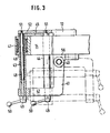
- Fig. 3 eine Draufsicht auf die lösbare Lagerung des Formatzylinders mit teilweise geschnittener schlittenförmiger Führung.
- 1 is a schematic side view of a flexographic printing machine,
- Fig. 2 is a side view of a format cylinder mounted on a format cylinder slide with an axially displaceable and pivotable bearing and
- Fig. 3 is a plan view of the detachable mounting of the format cylinder with a partially sectioned slide-shaped guide.
In dem Maschinengestell 1 der Flexodruckmaschine ist der mit einem nicht dargestellten Antrieb versehene Druckzylinder 2 gelagert. Das Maschinengestell 1 ist mit etwa radialen Tragarmen bzw. Konsolen 3 versehen, auf denen Formatzylinderschlitten 4 längsverschieblich geführt sind, die beidseits mit Lagerböcken 5 für die Formatzylinder 6 versehen sind. Die Formatzylinderschlitten 4 sind mit Spindeln zum Heranfahren der Formatzylinder 6 an den Druckzylinder 2 versehen.The
Auf dem Formatzylinderschlitten 4 ist der Farbwerksschlitten 7 längsverschieblich geführt, der mit dem Farbauftragswerk und der in diesem gelagerten Farbauftragswalze 8 versehen ist.The inking unit slide 7, which is provided with the inking unit and the inking
Zur Ausführung der "Druck-an"- und "Druck-ab"-Bewegungen sind die Lagerböcke 5 für die Formatzylinder mit eingearbeiteten Zylindern und mit mit Lippendichtungen versehenen Kolben versehen, wie sie beispielsweise in der DE-PS 29 41 521 beschrieben sind.To carry out the "pressure-on" and "pressure-down" movements, the
Um zum Austausch der hülsenförmigen Formatzylindermäntel auf einfache und schnelle Weise einen eine Seite des Formatzylinders 6 lagernden Lagerbock 5 entfernen zu können, ist dieser in unten näher beschriebener Weise auf Führungen schlittenartig verschiebbar gelagert, wobei die Führungen mit einem bügelförmigen Tragteil 9 verbunden sind, das den vorderen Teil des Formatzylinderschlittens 4 bildet und um die Achse 10 von diesem wegschwenkbar ist.In order to be able to easily and quickly remove a
Aus Fig. 2 sind die nach oben gerichteten Schenkel 11, 12 der Konsole 3 ersichtlich, auf denen die Lagerböcke 13, 14 für die Formatzylinderlager 15, 16 angeordnet sind, wobei sich zwischen den Lagerböcken und den Lagern die Druckmittel-Kolben-Zylinder-einheiten 17, 18 zum Ausführen der "Druck-an"- und "Druck-ab"-Bewegungen durch Anheben und Absenken der Lager 15, 16 befinden.From Fig. 2 the
Der Formatzylinder 6 ist mit Wellenzapfen 20, 21 versehen, die in Gleitlagerbuchsen 22, 23 gelagert sind, die mit kugeligen Außenseiten versehen sind, die in entsprechenden Kugelschalen der Lagerböcke gehaltert sind.The
Der Schenkel 11 der Konsole 3 ist beidseits mit Tragstücken 24, 25 versehen, an denen hydraulische Kolbenzylindereinheiten 26, 27 befestigt sind. Die Tragstücke 24, 25 können auch am Formatzylinderschlitten 4 befestigt sein. Die Kolbenstange 28 der Kolbenzylindereinheit 26 trägt an ihrem oberen Ende eine Stützschale 29, die zur Abstützung des Formatzylinders 6 von unten her gegen einen über einen Absatz verdichten Abschnitt 30 des Wellenzapfens des Formatzylinders 6 gefahren werden kann. Der äußere Abschnitt 31 des Wellenzapfens des Formatzylinders 6 ist gegenüber dem der Lagerung dienenden Abschnitt 20 über einen Absatz verjüngt und greift durch ein längliches Fenster 32 einesThe
Zugteils 33, das mit der Kolbenstange 34 der Kolbenzylindereinheit 27 verbunden ist. Das Zugteil 32 übergreift mit einem aufgeschraubten Joch 35 den äußeren Abschnitt 31 des Wellenzapfens, wobei das Joch 35 durch Einfahren der Kolbenstange 34 so weit abgesenkt werden kann, daß sich dieses stützend auf die Oberseite des Abschnitts 31 des Wellenzapfens legt. Wenn diese Stützposition erreicht ist, betätigt der mit der Kolbenstange 34 verbundene Hebel 36 den Mikroschalter 37. Dadurch wird erreicht, daß die "Druck-ab"-Position und der ausgekuppelte Antrieb zum Formatzylinder 6 verriegelt wird.
Wie aus Fig. 3 ersichtlich ist, ist mit dem Steg 12 des Formatzylinderschlittens 4 um den vertikalen Gelenkbolzen 40 schwenkbar der aus einem abgewinkelten Hebel bestehende Schwenkbügel 41 verbunden. In dem abgewinkelten Schenkel 42 des Schwenkbügels 41 sind parallel zueinander die aus den Stangen 43, 44 bestehenden Führungen befestigt. Die gegenüberliegenden Enden der Führungsstangen 43,44 sind durch den Steg 45 miteinander verbunden. Auf den Führungsstangen 43, 44 ist der Lagerbock 14 für das Lager 16 längsverschieblich geführt. Der Lagerbock 14 ist mit zwei Bohrungen 46 versehen, in denen Kugelbüchsen durch Klemmringe gehaltert sind, die auf den Führungsstangen 43, 44 laufen.As can be seen from FIG. 3, the
Die Führungsstangen 43, 44 sind mit axialen Bohrungen versehen, die Schraubbolzen 48 durchsetzen. Die äußeren Enden der Schraubbolzen 48 sind mit Kopfstücken 49 verbunden, die sich auf den Außenseiten des Schenkels 42 des Schwenkbügels 41 abstützen und mit Handgriffen 50 versehen sind. Die inneren Enden der Schraubbolzen 48 sind mit Gewinden 51 versehen, die in entsprechende Gewindebohrungen eines Wandteils 52 des Stegteils 12 des Formatzylinderschlittens 4 einschraubbar sind.The
Wie aus Fig. 2 ersichtlich ist, weist der Schwenkbügel 41 zwei gegabelte Lagerschenkel 54, 55 auf, die ein stegförmiges Lagerteil 56 des Formatzylinderschlittens 4 einfassen.As can be seen from FIG. 2, the
In Fig. 3 ist die ausgeschwenkte Stellung des Schwenkbügels 41 mit den Führungsstangen 43, 44 strichpunktiert eingezeichnet.In Fig. 3, the swiveled-out position of the
Zum Wechsel des hülsenförmigen Formatzylindermantels werden zunächst die Stützschale 29 und das Joch 35 des Zugteils 33 in ihre aus Fig. 2 ersichtlichen Stützstellungen gefahren. In dieser Stützstellung wird der Formatzylinder 6 allein an seinem linken Wellenzapfen an dessen Abschnitten 30, 31 gehalten, so daß nach Entfernung des Lagers 16 der Formatzylinder 6 in seiner Lage beharrt.To change the sleeve-shaped format cylinder jacket, the
Zum Entfernen des Lagers 16 wird zunächst die nicht dargestellte Arretierung oder Verriegelung des Lagerbocks 14 mit dem Steg 12 des Formatzylinderschlittens 4 gelöst. Nach diesem Lösen und nach einer eventuellen Lockerung der Lagerschalen des Lagers 16 läßt sich das Lager 16 durch axiales Bewegen des Lagerbocks 14 von dem Wellenzapfen 21 abziehen. Dabei wird der Lagerbock 14 so weit nach außen gezogen, daß er sich in der Nähe des Schenkels 42 des Schwenkbügels 41 befindet. Anschließend werden über die Handgriffe 50 die Schraubbolzen 48 gedreht, bis diese aus dem Stegteil 52 des Formatzylinderschlittens 4 herausgeschraubt sind. In dieser Lage läßt sich der Schwenkbügel 41 mit dem Lagerbock 14, der Kolbenzylindereinheit 18 und dem Lager 16 in die aus Fig. 3 ersichtliche strichpunktierte Stellung verschwenken. In dieser kann nun in üblicher Weise der hülsenförmige Formatzylindermantel von dem Formatzylinder 6 zum Austausch gegen einen anderen abgezogen werden.To remove the
Claims (3)
dadurch gekennzeichnet,
daß die Führungen (43, 44) mit ihren inneren Enden mit dem Maschinengestell oder dem Formatzylinderschlitten verriegelbar sind,
daß der Bügel (41) mit den Führungen (43, 44) für den Lagerbock (14) des lösbaren Lagers (16) das vordere Endstück einer Seite des Formatzylinderschlittens (4) bildet und
daß im Maschinengestell oder auf dem Formatzylinderschlitten (4) beidseits des ungelösten Lagers (15) zum Stützen des Formatzylinderkerns hydraulische Kolben-Zylinder-Einheiten (26, 27) angeordnet sind, von denen die Kolbenstange (28) des inneren Zylinders mit einer gegen einen inneren Teil (30) des Wellenzapfens des Formatzylinderkerns ausfahrbaren Stützschale (29) und die Kolbenstange (34) des äußeren Zylinders mit einem äußeren Abschnitt (31) des Wellenzapfens des Formatzylinderkerns übergreifenden, einziehbaren Stützjoch (35) versehen sind, das die obere Begrenzung eines fensterartigen Ausschnitts (32) eines Zugteils (33) bildet.1. Storage for format cylinder (6) of a printing press, preferably a flexographic printing machine, with exchangeable sleeve-shaped format cylinder sleeves,
characterized,
that the guides (43, 44) can be locked with their inner ends to the machine frame or the format cylinder slide,
that the bracket (41) with the guides (43, 44) for the bearing block (14) of the detachable bearing (16) forms the front end piece of one side of the format cylinder carriage (4) and
that in the machine frame or on the format cylinder slide (4) on both sides of the undissolved bearing (15) for supporting the format cylinder core hydraulic piston-cylinder units (26, 27) are arranged, of which the piston rod (28) of the inner cylinder with one against an inner Part (30) of the shaft journal of the format cylinder core extendable support shell (29) and the piston rod (34) of the outer cylinder are provided with an outer section (31) of the shaft journal of the format cylinder core, which extends over a retractable support yoke (35) which forms the upper limit of a window-like cutout (32) of a traction part (33).
Applications Claiming Priority (4)
| Application Number | Priority Date | Filing Date | Title |
|---|---|---|---|
| DE3444192 | 1984-12-04 | ||
| DE3444192 | 1984-12-04 | ||
| DE3500319 | 1985-01-07 | ||
| DE19853500319 DE3500319A1 (en) | 1984-12-04 | 1985-01-07 | STORAGE FOR FORMAT CYLINDERS OF A PRINTING MACHINE, PREFERABLY FLEXO PRINTING MACHINE, WITH REPLACABLE SLEEVE-SHAPED FORMAT CYLINDER MATERIALS |
Publications (3)
| Publication Number | Publication Date |
|---|---|
| EP0184180A2 true EP0184180A2 (en) | 1986-06-11 |
| EP0184180A3 EP0184180A3 (en) | 1988-01-20 |
| EP0184180B1 EP0184180B1 (en) | 1990-08-08 |
Family
ID=25827052
Family Applications (1)
| Application Number | Title | Priority Date | Filing Date |
|---|---|---|---|
| EP85115295A Expired - Lifetime EP0184180B1 (en) | 1984-12-04 | 1985-12-03 | Support for forme cylinders with exchangeable, sleeve-shaped printing formes in a printing machine, particularly for flexographic printing |
Country Status (4)
| Country | Link |
|---|---|
| US (1) | US4697516A (en) |
| EP (1) | EP0184180B1 (en) |
| CA (1) | CA1259223A (en) |
| DE (1) | DE3500319A1 (en) |
Cited By (9)
| Publication number | Priority date | Publication date | Assignee | Title |
|---|---|---|---|---|
| EP0279394A2 (en) * | 1987-02-20 | 1988-08-24 | M.A.N.-ROLAND Druckmaschinen Aktiengesellschaft | Retaining device for mounting a sleeve on a cylinder |
| EP0290853A2 (en) * | 1987-05-09 | 1988-11-17 | M.A.N.-ROLAND Druckmaschinen Aktiengesellschaft | Bearing for a printing unit cylinder |
| EP0485913A1 (en) * | 1990-11-15 | 1992-05-20 | MAN Roland Druckmaschinen AG | Bearing for a printing unit cylinder |
| EP0485912A1 (en) * | 1990-11-15 | 1992-05-20 | MAN Roland Druckmaschinen AG | Bearing for a printing unit cylinder |
| EP0656259A1 (en) * | 1993-12-01 | 1995-06-07 | Paper Converting Machine Company | Flexographic press adapted for short runs and method |
| EP0741010A2 (en) * | 1995-05-02 | 1996-11-06 | MAF S.p.A. | Support assembly for printing plateholder cylinders, particularly in flexographic printing machines |
| AT403034B (en) * | 1995-03-15 | 1997-10-27 | Helmut Ing Berger | Roll for machines for guiding web-like flat material |
| EP1010522A1 (en) * | 1998-12-14 | 2000-06-21 | Fischer & Krecke Gmbh & Co. | Device for handling printing cylinders |
| EP1080890A1 (en) * | 1999-08-20 | 2001-03-07 | Paper Converting Machine Company | Method and apparatus for exchanging a roll or a sleeve of a printing press |
Families Citing this family (25)
| Publication number | Priority date | Publication date | Assignee | Title |
|---|---|---|---|---|
| DE3702889A1 (en) * | 1987-01-31 | 1988-08-11 | Roland Man Druckmasch | DEVICE FOR APPLYING A SLEEVE TO A PRINTING CYLINDER |
| JP2512501Y2 (en) * | 1987-06-09 | 1996-10-02 | 株式会社 サト− | Carbon ribbon feeder for printer |
| DE4008501A1 (en) * | 1989-12-18 | 1991-06-20 | Windmoeller & Hoelscher | PRINTING MACHINE WITH PRESSORS WITH INTERCHANGEABLE SLEEVE-SHAPED PRESSING MACHINES |
| DE4005890A1 (en) * | 1990-02-24 | 1991-09-05 | Bielomatik Leuze & Co | Cliché sleeve mounting device |
| IT1253804B (en) * | 1991-11-21 | 1995-08-23 | EQUIPMENT FOR THE AUTOMATIC REPLACEMENT OF EQUIPPED PRINTING UNITS (INKWELLS), IN PARTICULAR FLEXOGRAPHIC MACHINES. | |
| GB2267869B (en) * | 1992-06-15 | 1995-07-26 | Windmoeller & Hoelscher | An inking unit having a cantilevered inking roller, as well as a cantilivered plate cylinder |
| DE9208023U1 (en) * | 1992-06-15 | 1992-11-26 | Windmoeller & Hoelscher, 4540 Lengerich, De | |
| US5237920A (en) * | 1992-06-22 | 1993-08-24 | Heidelberg Harris Inc. | Apparatus for supporting a cylinder in a rotary printing unit |
| US5289769A (en) * | 1992-08-17 | 1994-03-01 | W. O. Hickok Mfg., Co. | Method and apparatus for changing a printing sleeve |
| DE4408026A1 (en) * | 1994-03-10 | 1995-09-14 | Koenig & Bauer Ag | Printing unit for a multi-color web-fed rotary printing machine |
| DE4429891C2 (en) * | 1994-08-24 | 2003-05-08 | Koenig & Bauer Ag | Multicolor rotary printing press |
| ES2127658B1 (en) * | 1995-05-04 | 1999-12-16 | Comexi Sa | PROCEDURE FOR THE REPLACEMENT OF THE CLIFF SHIRT IN FLEXOGRAPHIC PRINTING MACHINES. |
| DE19603500A1 (en) * | 1996-01-31 | 1997-08-07 | Polywest Kunststofftechnik | Sleeve for a rotogravure roller, process for its production and working method of the device for the production |
| US5816154A (en) * | 1997-05-09 | 1998-10-06 | Bryce International, L.L.C. | Print cylinder support for axial removal of a cylindrical sleeve |
| US5806427A (en) * | 1997-08-29 | 1998-09-15 | Goss Graphic Systems, Inc. | Printing press having carriage mounted interchangeable plate cylinders |
| US5943955A (en) * | 1997-08-29 | 1999-08-31 | Goss Graphic Systems, Inc. | Printing press having cantilevered self-driven cylinders |
| IT1299666B1 (en) | 1998-05-05 | 2000-03-24 | Uteco Spa Roto Flexo & Convert | MULTI-COLOR CENTRAL DRUM FLEXOGRAPHIC ROTARY MACHINE |
| US6186068B1 (en) | 1999-05-18 | 2001-02-13 | Creo Srl | Method for holding printing sleeves in an imaging device |
| US6343547B1 (en) * | 1999-11-12 | 2002-02-05 | Heidelberger Druckmaschinen Ag | Cantilevered cylinder counterpoise device and method |
| ES2258989T5 (en) † | 2001-01-04 | 2011-01-17 | FISCHER & KRECKE GMBH & CO. | PROCEDURE FOR CHANGING A PRINT CYLINDER CAP AND PRINTING MACHINE FOR THE PERFORMANCE OF THIS PROCEDURE. |
| DE10343411B4 (en) * | 2003-09-19 | 2009-07-23 | Gallus Druckmaschinen Gmbh | Rotary printing machine and method for making freely accessible a printing cylinder or a linear guide cylinder |
| ITVR20040141A1 (en) * | 2004-09-10 | 2004-12-10 | Valentini Maria Grazia | SUPPORT AND RELEASE DEVICE FOR A HUB OF A CYLINDER FOR PRINTING MACHINE. |
| US20100122638A1 (en) * | 2008-11-18 | 2010-05-20 | C.G. Bretting Manufacturing Co., Inc. | Flexographic Printing Apparatus And Method |
| CN109334218A (en) * | 2018-10-09 | 2019-02-15 | 青州蒙特机械有限公司 | Roller for satellite-type flexible printing machine more exchange device automatically |
| CN113183623A (en) * | 2021-04-29 | 2021-07-30 | 无锡光群雷射科技有限公司 | Quick plate changing device and plate changing method |
Citations (4)
| Publication number | Priority date | Publication date | Assignee | Title |
|---|---|---|---|---|
| DE657921C (en) * | 1935-01-23 | 1938-03-17 | Vomag Betr S A G | Swiveling device for forme cylinders of rotary printing machines, especially rotogravure printing machines |
| DE891396C (en) * | 1942-09-22 | 1953-11-05 | Albert Schnellpressen | Gravure forme cylinder |
| US2925037A (en) * | 1956-12-07 | 1960-02-16 | Paul E Fischer | Apparatus for changing printing assembly |
| FR2353395A1 (en) * | 1976-06-02 | 1977-12-30 | Strachan & Henshaw Ltd | PRINTING MACHINE WITH PRINTER CYLINDER EQUIPPED WITH DETACHABLE SLEEVE |
Family Cites Families (6)
| Publication number | Priority date | Publication date | Assignee | Title |
|---|---|---|---|---|
| DE490994C (en) * | 1927-08-11 | 1930-02-05 | Johannisberg G M B H Maschf | Cylinder bearings, in particular forme cylinder bearings on rotary printing machines |
| US2460504A (en) * | 1944-10-24 | 1949-02-01 | William C Huebner | Printing apparatus |
| DE945148C (en) * | 1951-03-01 | 1956-07-05 | Albert Schnellpressen | Rotogravure printing machine |
| US2790384A (en) * | 1953-05-14 | 1957-04-30 | Druckmaschinenwerk Victoria Ve | Making-ready machines |
| DE1292957B (en) * | 1963-01-07 | 1969-04-17 | Peder Mortensen As | Arrangement on hollow pressure rollers |
| US3789757A (en) * | 1971-03-26 | 1974-02-05 | Motter J Printing Press Co | Printing press having automatic printing cylinder loading and unloading apparatus |
-
1985
- 1985-01-07 DE DE19853500319 patent/DE3500319A1/en active Granted
- 1985-12-03 EP EP85115295A patent/EP0184180B1/en not_active Expired - Lifetime
- 1985-12-03 CA CA000496749A patent/CA1259223A/en not_active Expired
- 1985-12-04 US US06/804,434 patent/US4697516A/en not_active Expired - Fee Related
Patent Citations (4)
| Publication number | Priority date | Publication date | Assignee | Title |
|---|---|---|---|---|
| DE657921C (en) * | 1935-01-23 | 1938-03-17 | Vomag Betr S A G | Swiveling device for forme cylinders of rotary printing machines, especially rotogravure printing machines |
| DE891396C (en) * | 1942-09-22 | 1953-11-05 | Albert Schnellpressen | Gravure forme cylinder |
| US2925037A (en) * | 1956-12-07 | 1960-02-16 | Paul E Fischer | Apparatus for changing printing assembly |
| FR2353395A1 (en) * | 1976-06-02 | 1977-12-30 | Strachan & Henshaw Ltd | PRINTING MACHINE WITH PRINTER CYLINDER EQUIPPED WITH DETACHABLE SLEEVE |
Cited By (12)
| Publication number | Priority date | Publication date | Assignee | Title |
|---|---|---|---|---|
| EP0279394A2 (en) * | 1987-02-20 | 1988-08-24 | M.A.N.-ROLAND Druckmaschinen Aktiengesellschaft | Retaining device for mounting a sleeve on a cylinder |
| EP0279394A3 (en) * | 1987-02-20 | 1989-12-20 | M.A.N.-Roland Druckmaschinen Aktiengesellschaft | Retaining device for mounting a sleeve on a cylinder |
| EP0290853A2 (en) * | 1987-05-09 | 1988-11-17 | M.A.N.-ROLAND Druckmaschinen Aktiengesellschaft | Bearing for a printing unit cylinder |
| EP0290853A3 (en) * | 1987-05-09 | 1990-04-04 | M.A.N.-Roland Druckmaschinen Aktiengesellschaft | Bearing for a printing unit cylinder |
| EP0485913A1 (en) * | 1990-11-15 | 1992-05-20 | MAN Roland Druckmaschinen AG | Bearing for a printing unit cylinder |
| EP0485912A1 (en) * | 1990-11-15 | 1992-05-20 | MAN Roland Druckmaschinen AG | Bearing for a printing unit cylinder |
| EP0656259A1 (en) * | 1993-12-01 | 1995-06-07 | Paper Converting Machine Company | Flexographic press adapted for short runs and method |
| AT403034B (en) * | 1995-03-15 | 1997-10-27 | Helmut Ing Berger | Roll for machines for guiding web-like flat material |
| EP0741010A2 (en) * | 1995-05-02 | 1996-11-06 | MAF S.p.A. | Support assembly for printing plateholder cylinders, particularly in flexographic printing machines |
| EP0741010A3 (en) * | 1995-05-02 | 1997-05-21 | Maf S P A | Support assembly for printing plateholder cylinders, particularly in flexographic printing machines |
| EP1010522A1 (en) * | 1998-12-14 | 2000-06-21 | Fischer & Krecke Gmbh & Co. | Device for handling printing cylinders |
| EP1080890A1 (en) * | 1999-08-20 | 2001-03-07 | Paper Converting Machine Company | Method and apparatus for exchanging a roll or a sleeve of a printing press |
Also Published As
| Publication number | Publication date |
|---|---|
| EP0184180B1 (en) | 1990-08-08 |
| DE3500319A1 (en) | 1986-06-05 |
| CA1259223A (en) | 1989-09-12 |
| DE3500319C2 (en) | 1987-07-30 |
| EP0184180A3 (en) | 1988-01-20 |
| US4697516A (en) | 1987-10-06 |
Similar Documents
| Publication | Publication Date | Title |
|---|---|---|
| EP0184180B1 (en) | Support for forme cylinders with exchangeable, sleeve-shaped printing formes in a printing machine, particularly for flexographic printing | |
| AT407508B (en) | PRINTING MACHINE | |
| EP0549936B1 (en) | Transfer cylinder with exchangeable sleeve, supported between two printing unit side walls | |
| DE69815115T2 (en) | PRINTING MACHINE WITH VARIABLE STOPPING MECHANISM | |
| EP1075945B1 (en) | Printing machine | |
| EP0741009B1 (en) | Printing machine | |
| DE19937796A1 (en) | Printing mechanism for a rotary printing press has two or more printing cylinders each with its own drive motor with linear separating adjustment through a sliding guide on a machine frame. | |
| DE2724653A1 (en) | PRINTING MACHINE | |
| EP0433622B1 (en) | Printing machine with pressure rollers including an exchangeable pressure sleeve | |
| EP0782920A2 (en) | Counterbalance and lift mechanism | |
| DE4406573B4 (en) | Printing unit of a rotary printing machine | |
| EP0858887B1 (en) | Printing machine | |
| EP0769373B1 (en) | Device for changing printing-cylinder-sleeves of printing machines | |
| CH686821A5 (en) | Inking with one end mounted screen roller and having one end stored format cylinder. | |
| EP2221179B1 (en) | Printing or inking unit | |
| DE2850397C2 (en) | Straightening machine for profile steel | |
| DE2949957C2 (en) | Printing unit for a web-fed rotary offset printing machine | |
| EP1732760B1 (en) | Printing mechanism of a printing machine having a pressure roller | |
| DE2723432C3 (en) | Table stop for a punching machine | |
| DE697501C (en) | Device for inserting and extending the forme cylinder in rotary printing machines, in particular rotogravure printing machines | |
| DE10103631A1 (en) | Rotary press | |
| EP3653383B1 (en) | Inking unit of a printing machine and method for fixing at least one inking cylinder in a slidable carriage of an inking unit | |
| EP3653382B1 (en) | Releasable bearing assembly of an inking cylinder of a printing machine | |
| DE3112995C2 (en) | Printing unit for a small offset printing machine | |
| EP1932667A1 (en) | Printing device for a variable format roller printing press |
Legal Events
| Date | Code | Title | Description |
|---|---|---|---|
| PUAI | Public reference made under article 153(3) epc to a published international application that has entered the european phase |
Free format text: ORIGINAL CODE: 0009012 |
|
| AK | Designated contracting states |
Kind code of ref document: A2 Designated state(s): FR GB IT |
|
| PUAL | Search report despatched |
Free format text: ORIGINAL CODE: 0009013 |
|
| AK | Designated contracting states |
Kind code of ref document: A3 Designated state(s): FR GB IT |
|
| 17P | Request for examination filed |
Effective date: 19880210 |
|
| 17Q | First examination report despatched |
Effective date: 19890621 |
|
| GRAA | (expected) grant |
Free format text: ORIGINAL CODE: 0009210 |
|
| AK | Designated contracting states |
Kind code of ref document: B1 Designated state(s): FR GB IT |
|
| ITF | It: translation for a ep patent filed |
Owner name: BUGNION S.P.A. |
|
| GBT | Gb: translation of ep patent filed (gb section 77(6)(a)/1977) | ||
| ET | Fr: translation filed | ||
| ITTA | It: last paid annual fee | ||
| PLBE | No opposition filed within time limit |
Free format text: ORIGINAL CODE: 0009261 |
|
| STAA | Information on the status of an ep patent application or granted ep patent |
Free format text: STATUS: NO OPPOSITION FILED WITHIN TIME LIMIT |
|
| 26N | No opposition filed | ||
| PGFP | Annual fee paid to national office [announced via postgrant information from national office to epo] |
Ref country code: GB Payment date: 19921124 Year of fee payment: 8 |
|
| PGFP | Annual fee paid to national office [announced via postgrant information from national office to epo] |
Ref country code: FR Payment date: 19921208 Year of fee payment: 8 |
|
| PG25 | Lapsed in a contracting state [announced via postgrant information from national office to epo] |
Ref country code: GB Effective date: 19931203 |
|
| GBPC | Gb: european patent ceased through non-payment of renewal fee |
Effective date: 19931203 |
|
| PG25 | Lapsed in a contracting state [announced via postgrant information from national office to epo] |
Ref country code: FR Effective date: 19940831 |
|
| REG | Reference to a national code |
Ref country code: FR Ref legal event code: ST |