EP0183265A2 - Appareil pour la détection de pression dans une conduite d'aspiration - Google Patents
Appareil pour la détection de pression dans une conduite d'aspiration Download PDFInfo
- Publication number
- EP0183265A2 EP0183265A2 EP85115101A EP85115101A EP0183265A2 EP 0183265 A2 EP0183265 A2 EP 0183265A2 EP 85115101 A EP85115101 A EP 85115101A EP 85115101 A EP85115101 A EP 85115101A EP 0183265 A2 EP0183265 A2 EP 0183265A2
- Authority
- EP
- European Patent Office
- Prior art keywords
- suction pipe
- pipe pressure
- signal
- internal combustion
- combustion engine
- Prior art date
- Legal status (The legal status is an assumption and is not a legal conclusion. Google has not performed a legal analysis and makes no representation as to the accuracy of the status listed.)
- Granted
Links
Images


Classifications
-
- G—PHYSICS
- G01—MEASURING; TESTING
- G01L—MEASURING FORCE, STRESS, TORQUE, WORK, MECHANICAL POWER, MECHANICAL EFFICIENCY, OR FLUID PRESSURE
- G01L23/00—Devices or apparatus for measuring or indicating or recording rapid changes, such as oscillations, in the pressure of steam, gas, or liquid; Indicators for determining work or energy of steam, internal-combustion, or other fluid-pressure engines from the condition of the working fluid
- G01L23/24—Devices or apparatus for measuring or indicating or recording rapid changes, such as oscillations, in the pressure of steam, gas, or liquid; Indicators for determining work or energy of steam, internal-combustion, or other fluid-pressure engines from the condition of the working fluid specially adapted for measuring pressure in inlet or exhaust ducts of internal-combustion engines
Definitions
- the present invention relates to a suction pipe pressure detection apparatus for detecting suction pipe pressure in an internal combustion engine. More particularly, the present invention relates to a suction pipe pressure detection apparatus for detecting suction pipe pressure in an internal combustion engine which is provided with a throttle valve for each cylinder, i.e., in a so-called independent suction type internal combustion engine.
- the air intake amount for multi-cylinder engines has normally been calculated based upon the suction pipe pressure measured by a pressure sensor as an average value for all of the cylinders or detected by an airflow meter.
- the apparatus for detecting the intake air amount for controlling independent cylinder type internal combustion engines the most commonly used type has been a simple structure using an airflow meter. That is, an airflow meter is fitted on the upstream side of the throttle valves where a number of suction pipes meet.
- an airflow meter is fitted on the upstream side of the throttle valves where a number of suction pipes meet.
- For detecting the suction pipe pressure there has been proposed a system having a newly provided communicating vessel connected with each suction pipe which allows an averaged pressure to be detected.
- the provision of the airflow meter in the portion where the suction pipes meet means that the airflow meter produces resistance to the intake air and consequently impairs the above merit.
- a primary object of the invention is the provision of an excellent suction pipe pressure detection apparatus for the independent cylinder type internal combustion engine, the apparatus being capable of accurate detection of the suction pipe pressure in the internal combustion engine with a simple structure while maintaining the advantages of the independent cylinder arrangement.
- Another object of the invention is the provision of accurate suction pressure signals for various control units controlling the internal combustion engine and thereby maximizing the operation of the internal combustion engine.
- a further object of the invention is the provision of an accurate suction pipe pressure signal to form the foundation for the detection of the air intake amount, which is one of the most important data in controlling the internal combustion engine.
- Still another object of the invention is the provision of an accurate suction pipe pressure signal for the electronic fuel injection apparatus as the basis for its deciding the fuel injection time.
- a still further object of the invention is the provision of means which enables, by detecting the suction pipe pressure for just one cylinder in the least case in the independent cylinder type internal combustion engine, the values of the suction pipe pressure for other cylinders to be known during the period of time from the above detection to the next detection of the suction pipe pressure of that cylinder.
- the suction pipe pressure detection apparatus of the invention for detecting the suction pipe pressure of the internal combustion engine having a throttle valve in the suction pipe for each cylinder includes the following:
- the apparatus of the present invention is provided with engine speed detection means for detecting the engine speed of the internal combustion engine for generating an engine speed signal. Further, the inventive apparatus produces a good effect through the correction made by the correction means to the suction pipe pressure signal in accordance with the throttle-opening. signal and the engine speed signal.
- the apparatus of the invention is provided with, in addition to the engine speed detection means, intake air amount computing means for generating an air intake quantity signal corresponding to the suction pipe pressure signal and the engine speed signal, and the air intake quantity signal is corrected according to the throttle-opening signal by the correction means, which also produces a good effect.
- the suction pipe pressure detection means of the invention is means for detecting pressure in a suction pipe for a cylinder in synchronism with a crank angle in an internal combustion engine.
- a crank angle implies that the detection of the suction pipe pressure is to be carried out while the relevant cylinder is correctly at the suction stroke. Therefore, the above means can be provided by using a conventional suction pressure sensor and adapting the output of the sensor to be sensed at the predetermined crank angle.
- the engine speed detection means is means for detecting the engine speed of the internal combustion engine.
- the means can be simply provided by using a crank angle detection means conventionally used with the internal combustion engines and adapting the number of outputs thereof at a unit time to be counted.
- the predetermined crank angle for the suction pipe pressure detection means can simply be detected by using the engine speed detection means and a cylinder distinction sensor conventionally used with the internal combustion engines.
- the throttle-opening detection means is means for detecting opening of a throttle valve provided for a suction pipe for each cylinder. While the opening of each throttle valve must be detected if all the throttle valves are independently controlled and therefore all the openings are independent from one another, detecting the opening of only one of the throttle valves is sufficient if all the throttle valves operate in conjunction. The detection in this case is carried out more frequently than the detection made by the suction pipe pressure detection means. As stated above, the suction pipe pressure detection means performs the detection at each suction stroke of a cylinder, namely, the detection is made at intervals of 720° crank angle (CA) in the internal combustion engine for a specific cylinder.
- CA crank angle
- the throttle-opening detection means can be provided by an arrangement able to detect the opening in synchronism with the crank angle smaller than 720° CA/N, for example, or at intervals of periods shorter than the time period required for the rotation through the crank angle of 720° CA/N.
- the correction means is such that it corrects the suction pipe pressure at a suction stage detected by the suction pipe pressure detection means, according to the throttle opening detected by the throttle opening detection means at higher frequency, and, if necessary, the engine speed, and provides a value corresponding to a suction pipe pressure.
- the suction pipe pressure detection means takes the data only in synchronism with the suction stroke once for every 720° CA. Thus, when it becomes necessary to get the suction pipe pressure at any time, the value corresponding to the suction pipe pressure is provided through correction of the actually measured suction pipe pressure according to the throttle opening.
- the air intake amount computing means is means for computing the atmospheric pressure-compensated intake air amount for the internal combustion engine from results detected by the suction pipe pressure detection means, the number of revolution detection means, and the throttle opening detection means. Therefore, as the arrangement for constituting the computing means is considered such as a non-programmable-type computing circuit to which the detected results from the above three means are input, a programmable-type computing apparatus with a microcomputer used therein in place of the above mentioned non-programmable-type computing circuit, and a design enabled, in order to increase the operation speed, to retrieve necessary data from a table provided in advance.
- the reference fuel injection amount computing means computes the amount of fuel to be supplied by injection to the internal combustion engine from detected results by the engine speed detection means and the suction pipe pressure detection means. This will be formed with an arithmetic and logic circuit using a microcomputer conventionally mounted on the internal combustion engine or with a discrete arithmetic circuit. The computation may be obtained through actual operations or retrieval of data from a previously provided table.
- the suction pipe pressure detection apparatus of the invention detects the suction pipe pressure of a specific cylinder detected by the suction pipe pressure detection means in synchronism with the crank angle and constantly provides the suction pipe pressure of the internal combustion engine, i.e., the above detected suction pipe pressure as basic data corrected properly by the correction means according to the value detected by the throttle opening detection means.
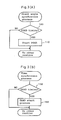
- Arrangements of various means used in the first preferred embodiment are represented in two ways as shown in Figs. 1(A) and I(B).
- the arrangement of Fig. 1(B) is provided with means for detecting engine speed which is provided in addition to that of Fig. 1.
- Fig. 1(B) is provided with means for detecting engine speed which is provided in addition to that of Fig. 1.
- Fig. 2 is a schematic diagram showing a control system for a four-cylinder independent suction type internal combustion engine on which the suction pipe pressure detection apparatus of the embodiment is mounted.
- a four-cylinder engine 10 has a suction pipe 11 for each cylinder communicating with a throttle. valve 12 interlocked with an accelerating pedal (not shown) and a fuel tank (not shown).
- the suction pipe 10 is provided with a fuel injection valve 13 for injecting fuel into the suction pipe.
- the cylinders are arranged in the order of the first cylinder, the second cylinder, the third cylinder, and the fourth cylinder from the top down in Fig. 2.
- An ignition plug 14 provided for each cylinder is properly supplied with a suitable high voltage from a distributor 15, whereby the ignition timing is determined.
- a throttle-opening sensor 16 detects the opening of the throttle valve 12 and outputs an analog output voltage proportional to the opening of the throttle valve 12.
- an intake pressure sensor 17 formed by a pressure sensor for detecting the suction pipe pressure on the downstream side of the throttle valve 12 in the suction pipe for the first cylinder.
- a water temperature sensor 18 detects the cooling water temperature for the internal combustion engine 10
- an oxygen sensor 19 detects oxygen concentration in the exhaust gas from the engine 10
- an intake-air temperature sensor 20 detects the temperature of the intake air.
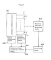
- Outputs of these various sensors and operations of these various devices are centrally controlled by an electronic control 30.
- the electronic control 30 is shown in Fig. 2 as an arithmetic and logic circuit using a microcomputer and operates with power supplied from a car battery 21 through a key switch 21.
- the central processing unit (CPU) 31 of the microcomputer performs various arithmetic operations, and processes data according to control programs and tables (to be described later) stored in a read only memory (ROM) 32.
- ROM read only memory
- RAM random access memory
- An input port 34 receives outputs from the above mentioned various sensors such as the throttle-opening sensor 16, intake pressure sensor 17, water temperature sensor 18, oxygen sensor 19, intake-air temperature sensor 20, a cylinder distinction signal from the distributor 15, and a rotational angle signal corresponding to a crank angle.
- the input port 34 includes an A/D converter, a waveform shaper, and so on, and properly supplies necessary digital data for the CPU 31.
- An output port 35 in response to operation results of the CPU 31, outputs timing and duration data for opening the valve to the fuel injection valve 13 for each cylinder, and supplies the distributor 15 with a signal for determining the ignition timing of the ignition plug 14.
- These component units of the electronic control 30 are interconnected by a data and address bus 36.
- Figs. 3(A), 3(B) and Fig. 4 show flow charts for the suction pipe pressure detection programs stored in the ROM 32.
- Figs. 3(A) and 3(B) show flow charts of routines for determining the timing to receive outputs of the sensors.
- a routine is repeatedly executed by the CPU 31 in synchronism with the crank angle of the internal combustion engine 10 for controlling the timing to detect the output of the intake pressure sensor 17.
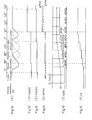
- the timing to detect the PS means the time at which the intake pressure sensor 17 is generating an output to indicate the negative pressure condition at the suction stroke of the first cylinder as shown in the timing chart of Fig. 5(A).
- the detecting of the output PS of the sensor is, as is apparent from the timing chart of Fig. 5(A), started at any point during the period when the curve drawn in a solid line showing the suction pipe pressure of the first cylinder is largely depressed (between around 0° CA and 360° CA). In the present embodiment, at about 160° CA. If it is judged at the present step 100 of Fig.
- Fig. 3(B) shows a routine for detecting the output (TA) of the throttle-opening sensor 16 which is repeatedly executed by the CPU 31 at intervals of predetermined periods of time.
- TA the output of the throttle-opening sensor 16
- the step 160 controls the start of a series of processes such that the output TA of the throttle-opening sensor 16 is A/D converted and this value (TAAD) is stored in a predetermined address, and thus the detecting of the TAAD is started.
- Fig. 5(D) is a timing chart showing the detecting of the output TA of the throttle-opening sensor 16. As shown in the chart, the detecting of the A/D converted value of the TA, TAAD, is repeated at intervals of predetermined periods T [ms].
- the predetermined period T [ms] is always smaller than the above mentioned period of the detecting of the A/D converted value of the suction pipe pressure, PSAD, i.e., the detecting of the TAAD is carried out at higher frequency than the detecting of the PSAD.
- the detecting timing of the TAAD is not necessarily in synchronism with such a short period T as in the present embodiment, but it may be in synchronism with some crank angle smaller than the crank angle 720° CA of the PSAD detection timing.
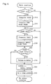
- Fig. 4 indicates the main routine of the present embodiment to compute the suction pipe pressure PM of the internal combustion engine 10.
- This routine is repeatedly executed by the CPU 31 at intervals of predetermined periods of time.
- the CPU 31 enters into the processing in this routine, it is judged at the step 200 whether or not the A/D conversion of the output PS of the intake pressure sensor 17 (a series of processes started in the above described step 110) has been finished and whether the newest PS value has been detected. If, at this step, it is judged that the A/D conversion of the newest PS has not been finished, the routine advances to the step 230 (to be described later), and if A/D conversion is judged to have been finished the process in the next step 210 is started.
- the A/D converted value of the output PS of the intake pressure sensor 17, PSAD is computed in the CPU 31. And from the A/D converted value, PSAD, is computed (step 220) reference suction pipe pressure PMB (the true suction pipe pressure at the time when the output PS of the intake pressure sensor 17 was detected). That is, the PMB is computed at every 160° CA of the crank angles (Fig. 5(C)).
- the following steps 230 and 240 are for executing similar processes as executed in the steps 200 and 210, that is, it is judged whether or not the detection of the throttle opening TA at the step 160 in Fig.
- step 280 (to be described later) is executed. If it has been finished, then computation of the A/D converted value of the TA, TAAD, is executed (step 240). From the value TAAD, through processing in the next step 250, is calcualted a correction value of the reference suction pipe pressure PMB, PMTAi, and the same is stored in the RAM 33. Both the above mentioned PMB and the PMTAi in the present step may be obtained either through actual computation or, in order to speed up the operation, through retrieval from a table which has been stored in the ROM 32 in advance.
- the engine speed NE can also be taken into consideration in addition to the throttle opening TA, and the PMTAi may be calculated from the TA and NE. Since the suction pipe pressure varies with the engine speed if the throttle opening is kept the same, the PMTAi calculated from both the values will give the correction value with higher accuracy.
- the next step 260 it is judged whether or not the PMTAi calculated in the step 250 was at a time immediately before the A/ D conversion of the PS is to be carried out. As shown in Figs. 5(B) and (D), the PSAD is calculated at intervals of 720° and the TAAD is calculated at intervals of predetermined periods of T.
- the frequency of the calculation of the TAAD is always set higher than that of the PSAD. Therefore, a computation of the TAAD must have been carried out within the small time difference of a computing timing of the PSAD. For such a reason, it is judged in the present step whether or not the PMTAi was calculated from the TAAD calculated at a time immediately before the calculation time of the PSAD. If the PMTAi is imnediately before the timing of the PSAD, then, the step 270 is executed and the value of the PMTAi is assigned to the variable PMTAB; otherwise, the routine advances to the step 280.
- the relationship between the PMTAi and PMTAB is shown in Fig. 5(D).
- the steps 280 and 290 are for computing the suction pipe pressure PM.
- the value PM is calculated from the newest value of PMB and values PMTAB and PMTAi by the formula: that is the value of PMB is provided with correction by the value (PMTAi - PMTAB) which is calculated at the step 280.
- the PMTAB is the value that was calculated immediately before the PMB was calculated as described in the foregoing, and so, the influence of the throttle opening TA on the suction pipe pressure (PMTAB) should have already been included in the value of PMB.
- the suction pipe pressure PM and the engine speed NE will naturally vary, but the variation in the PM cannot be calculated until another predetermined crank angle (160° CA) is reached. Therefore, to provide the information on the suction pipe pressure PM of the internal combustion engine 10 while the detection of the PM is impossible, the difference between the PMTAi, which has been calculated from the present throttle opening TA or from both the TA and the engine speed NE, and PMTAB is calculated. In other words, the variation in the suction pipe pressure due to change in the throttle opening TA, and change in the engine speed NE, is computed and this value is added to the PMB thereby always providing computation of the suction pipe pressure PM (Fig. 5(E)). The shaded portion in Fig. 5(D) indicates the correction width for the suction pipe pressure in accordance with the throttle opening TA, or with the throttle opening TA and the engine speed NE.
- the intake pressure sensor 17 was provided only for the suction pipe of one cylinder of a four-cylinder independent suction type internal combustion engine, it is apparent that the embodiment can likewise be applicable to such cases where two intake air pressure sensors are provided for a six-cylinder internal combustion engine or four intake air pressure sensors are provided for an eight-cylinder internal combustion engine, or, in brief, applicable to internal combustion engines for which the intake air pressure sensors fewer than the cylinders are provided.
- the thus calculated PM value can be widely used for. various controlling purposes which are known, such as for calculating the fuel injection amount to keep the air-fuel ratio for the internal combustion engine 10 at a desired level, and for calculating the ignition timing for controlling the output torque and emission of the internal combustion engine 10.
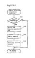
- Figs. 6(A) and 6(B) show an application example to determine the ignition timing for an internal combustion engine 10 with the use of the suction pipe pressure PM detected in the suction pipe pressure detection apparatus of the present embodiment.
- Fig. 6(A) is a flow chart for determining the ignition timing and
- Fig. 6(B) is an explanatory drawing of a table to be used in the flow chart.
- the spark advance angle calculating routine in Fig. 6(A) is such that it is repeatedly executed as a part of the main routine or an independent routine for controlling internal combustion engine 10. In this routine, the spark advance angle, or the ignition timing, which contributes to the best operation of the internal combustion engine is calculated.
- step 300 it is judged whether or not it is the right time to compute the spark advance angle, that is, whether any cylinder in the internal combustion engine 10 is about to need ignition or not is determined according to the crank angle data or the like. If it is determined that the spark advance angle should be computed now, the steps 310 to 330 are executed; otherwise, this routine is ended.
- the current engine speed NE of the internal combustion engine 10, and the suction pipe pressure PM are detected, that is, operating conditions of the internal combustion engine 10 necessary for computing the spark advance angle are detected.
- the engine speed NE is always possible to detect from the rotary angle signal from the distributor 15, and the suction pipe pressure PM is available from the results of the computations in the above described embodiment.
- the routine of Fig. 4 is executed and the suction pipe pressure PM of the internal combustion engine 10 is already obtained.
- the spark advance angle is given based on the above two values NE and PM and through retrieval from the table for computing the spark advance angle as shown in Fig. 6(B).
- the result of the table retrieval is stored in the RAM 33 and the ignition is carried out in response to the data in the RAM through an ignition executing routine (not shown).
- the suction pipe pressure value PM provided through the computations in the above embodiment is not at all different from the suction pipe pressure value used as a parameter in the control of the internal combustion engines 10, and therefore the same can be widely used as a parameter for. various existing control systems.
- FIG. 7 is a drawing showing basic arrangement of various means in the present embodiment.
- Intake air quantity computing means in Fig. 7 includes correction means. Similar to the first embodiment, schematic arrangement of devices in the present embodiment is as shown in Fig. 2, and so, description thereof is omitted here. What is different from the first embodiment lies in the programs in the ROM 32 in the computer 30; general remarks about the same will be given in the following with reference to flow charts of Fig. 8(A), (B) and Fig. 9.
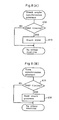
- Fig. 8(A) and (B) are flow charts for determining timing to detect outputs of sensors.
- Fig. 8(a) represents the routine repeatedly executed by CPU 31 in synchronism with the crank angle of the internal combustion engine 10 for controlling twice the timing for detecting the output of the intake pressure sensor 17 for one cycle (two rotations of the crank shaft).
- the time for detecting the PS means both the time when the intake pressure sensor 17 is generating the output to indicate the negative pressure condition at the suction stroke of the first cylinder and the time when the suction pipe pressure, after the suction stroke, has become equal to.
- the detecting of the outputs PS is, as apparent from the timing chart of Fig. 10(A), started at any point during the period when the curve drawn in a solid line showing the suction pipe negative pressure of the first cylinder is largely depressed (between around 0° CA and 360° CA), and again when indicating constant value (between around 360° CA and 720° CA). In the present embodiment at about 160° CA and 680°.
- an A/D conversion process of intake pressure sensor 17 is started in the next step 410, and a series of processes are started such that the output of the intake pressure sensor 17 is A/D converted in the input port 34 and its value PSAD 1 (PS value at 160° CA), and PSAD 2 (PS value at 680° CA) (Figs. 10(B), (C)) is temporarily stored in a buffer. If it is other time than that when the crank angle is about 160° CA or 680° CA, the routine is ended without starting any of the above described processes in the step 410 and another routine is executed.
- Fig. 8(B) shows a routine for taking up the output (TA) of the throttle-opening sensor 16 which is repeatedly executed by the CPU 31 at intervals of predetermined periods of time.
- TA the output of the throttle-opening sensor 16
- the step 430 controls start of a series of processes such that the output TA of the throttle-oepning sensor 16 is A/D converted and this value (TAAD) is stored in a predetermined address, and thus detecting of the TAAD is started.
- 10(E) is a timing chart showing the detecting of the output of the throttle opening sensor TA.
- the detecting of the A/D converted value of the TA, TAAD is made at intervals of predetermined periods T.
- the predetermined period T is always shorter than the above mentioned period of detecting A/D converted value of the suction pipe negative pressure, PSAD, i.e., the detecting of the TAAD is carried out at higher frequency than the detecting the PSAD.
- Fig. 9 indicates the main routine of the present embodiment which computes the intake air quantity Q for the internal combustion engine 10.
- This routine is repeatedly executed by the CPU 31 at intervals of predetermined periods of time.
- the CPU 31 enters into the processing in this routine, it is judged at the step 440 whether or not the A/D conversion of the output PS of the intake pressure sensor 17 (a series of processes started in the above described step 410) has been finished and the newest PS value has been detected. If, at this step, it is judged that the A/D conversion of the newest PS has not been finished, the routine advances to the step 520 (to be described later), and if the A/D conversion is judged to have been finished the process in the next step 450 is executed.
- the A/D converted value of the output PS of the intake pressure sensor 17, PSAD is computed in the CPU 31. And it is judged whether the A/D converted value, PSAD, was detected in synchronism with the crank angle 160° CA, or detected in synchronism with the crank angle 680° CA (step 460). If it is the data at 160 0 CA, a reference intake air quantity QPMC is computed through the processes in the steps 470 to 490, and if it is the data at 680° CA, atmospheric pressure compensation factors KPM, KTA for QPM, QTA (to be described later) are computed through processes in the steps 500 and 510. Computation of the QPMC will first be described.
- the value of the PSAD computed in the step 450 is assigned to the variable PSAD1 as a value indicating the negative pressure condition of the intake air (step 470), and the intake air quantity QPM is computed from multiplying value PSAD1 and the engine speed NE of the internal combustion engine 10 (step 480).
- This computation is not at all different from the above-described computation of the intake air quantity Q and the quantity is provided either through computation in the CPU31 or retrieval from a table stored in the ROM 32 in advance.
- the thus obtained intake air quantity QPM is multiplied by the atmospheric pressure compensation factor KPM in the following step 490 and a reference intake air quantity QPMC is thereby provided.
- the atmospheric pressure compensation factor KPM used in the above computation of the reference intake air quantity QPMC and the atmospheric pressure compensation factor KTA for intake air quantity correction value QTA (described later) to be calculated based on the throttle opening TA are computed in the steps 500 and 510.
- the value of PSAD computed in the step 450 is assigned.
- the variable PSAD 2 is assigned.
- the two atmospheric pressure compensation factors KPM and KTA are computed.
- These two atmospheric pressure compensation factors KPM and KTA are a function of PSAD 2 and are provided either through computation in the CPU 31 or retrieval on respectively prepared tables stored in the ROM 32.
- the intake air quantity also varies even under the same suction pipe pressure or the throttle valve.
- the next step 520 is executed.
- similar processes as executed in the step 440 are executed, that is, it is judged whether or not the detecting of the throttle opening TA at the step 430 in Fig. 8(B) has been finished and the newest TA value has been detected, and if it has not been finished, the step 590 (to be described later) is executed, and if it has been finished, then a series of processes in the steps 530 to 580 are executed.
- the processes in the steps 530 to 580 are for computation of the value ( ⁇ QTA) to be added to or subtracted from the above described reference intake air quantity QPMC computed in the step 490.
- the A/D converted value, TAAD, of the throttle opening TA is calculated and supplied to the CPU 31 to be processed by the same.
- the intake air quantity correction value QTA to be calculated from the throttle opening TA is computed (step 540).
- This computation of QTA similar to the above described QPM, is carried out either through direct computation or through retrieval from a table.
- the above QTA is multiplied by the compensation factor KTA obtained from the newest detected result of atmospheric pressure (PSAD 2) computed in the step 500, and thus, the intake air quantity correction value QTAC obtained from the throttle opening TA provided with atmospheric pressure compensation is computed.
- the PSAD 1 is calculated at intervals of 720° CA of crank angles and the TAAD is calculated at intervals of predetermined periods of T, and the frequency of the calculation of the TAAD is always set higher than that of the PSAD. Therefore, a computation of the TAAD must have been carried out within a small time difference of the computing timing of the PSAD 1. For such reason, it is judged in the present step whether or not the QTAC was calculated from the TAAD calculated at the timing immediately before the calculation timing of the PSAD 1.
- the step 570 is executed and the value of the QTAC is assigned to the variable QTAB; otherwise, the routine advances to the step 580. Relationship between the QTAC and QTAB is shown in Fig. 10(E).
- the step 580 is the step for computing QTA, the value to be added to or subtracted from the intake air quantity.
- the ⁇ QTA is calculated from the newest value of the QTAC and the value of the QTAB by the following formula:
- the QTAB is the value that was calculated immediately before the QPMC was calculated as described in the foregoing, and so, the influence of the throttle opening TA on the intake air quantity (QTAB) should have already been included in the value of QPMC. If, however, the opening of the throttle valve 12 is regulated in either the opening or closing direction after the QPMC was calculated, the intake air quantity and the engine speed NE will naturally vary, but the variation in the intake air quantity cannot be computed until another crank angle (160° CA) is reached. Therefore, to provide for computation of the intake air quantity for the internal combustion engine 10 while the detection of the intake air quantity is impossible, the difference between the QTAC, which has been calculated from the present throttle opening TA and the engine speed NE, and the QTAB is computed.
- the variation in the intake air quantity due to changes in the throttle opening TA and the engine speed NE is computed.
- This value ( ⁇ QTA) is added to the QPM C (step 590) to thereby always provide by calculation the intake air quantity Q (Fig. 10(F)) for the internal combustion engine 10.
- the shaded portion in Fig. 10(E) indicates the correction width of the intake air quantity (AQTY) in accordance with the throttle opening TA and the engine speed NE.
- the thus calculated intake air quantity Q can be widely used for various controlling. purposes which have been in practice, such as for calculating the fuel injection amount to keep the air-fuel ratio for the internal combustion engine 10 at a desired level, and for calculating the ignition timing for controlling the output torque and emission of the internal combustion engine 10.
- the third and fourth embodiments are the same as the first embodiment in schematic arrangement of various devices as shown in Fig. 2. And the third and fourth embodiments are the same in basic arrangement of various means as shown in Fig. 11, but they are differrent in the programs stored in their respective ROMs 32.
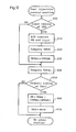
- the flow chart for the third embodiment is shown in Fig. 12 and that for the fourth embodiment is shown in Figs. 14(A), (B). First, the third embodiment will be described with reference to the flow chart of Fig. 12.
- the routine of Fig. 12 is that which is repeatedly executed by the CPU 31 at intervals of predetermined periods of time.
- the CPU 31 enters into this routine first, it is judged in the step 600 whether or not it is right time, i.e., a predetermined crank angle is reached, for detecting the negative suction pipe pressure PM. While the suction pipe pressures PM for various cylinders vary as the crank angles change as shown in the timing chart of Fig.
- the routine advances to the step 640 (described later), but if it is the predetermined right angle, the next step 610 is executed.
- the output of the intake pressure sensor 17 is detected and A/D converted.
- a reference fuel injection amount (a period of time during which the fuel injection valve 13 is open) TPPM is computed (step 620). That is, the TPPM is computed at every 180° of the crank angle (Fig. 13(B)).
- the newest value of a TPTAi (described later) is assigned to a variable TPTAB.
- the step 640 is a step that is executed without fail every time the present routine is processed, in which the output TA of the throttle-opening sensor 16 is detected and the correction value TPTAi for the fuel injection amount TP is computed from the value TA and the present engine speed NE of the internal combustion engine 10 and the result is stored in the RAM 33.
- the TPTAi mentioned in the description of the preceding step 630 was that which had already been computed at the step 640 and stored in the RAM 33 when the present routine had been executed immediately before that step 630 was executed, and this value of the TPTAi, in fact, was assigned to the variable TPTAB in the step 630.
- These situations. are represented in Fig. 13(C).
- the period of time T for detecting output TA is the period at intervals of which the routine of Fig. 12 is repeated.
- the timing for computation of the TPPM (in synchronism with the crank angle) executed in the step 620 is independent from the above T, and the value obtained immediately before that timing becomes the TPTAB, and thereafter the TPTAi is computed at intervals of the periods T.
- the computation of both the value TPPM in the earlier step and the value TPTAi in the present step can be made either through actual arithmetic operation or through retrieval from a table which has been stored in the ROM 32 in advance.
- step 650 it isjudged whether it is right time or not to compute the fuel injection period TAU during which the fuel injection is carried out.
- the results of the computation of the TAU and the injection timing are shown in Fig. 13(D) and the fuel injection is carried out during the predetermined stroke of each cylinder. Therefore, until that time comes, the CPU 31 ends the processing of the present routine without computing the TAU to execute various other processes. If it is judged in the present step that it is the right time for computing the TAU, then the following step 660 is executed.
- the step 660 is a step for computing a fuel injection time TP, which is obtained from the newest TPPM value and the values of TPTAB and TPTAi by the following formula: that is, by providing the value of the TPPM with a correction value (TPTAi - TPTAB).
- the TPTAB is the value that was computed immediately before the TPPM was computed as described in the foregoing, and so, the influence of the throttle opening TA on the fuel injection period (TPTAB) should have already been included in the value of TPPM. If, however, the opening of the throttle valve 12 is regulated in either the opening or closing direction after the TPPM was calculated, the suction pipe pressure PM will naturally vary, but the variation in the suction pipe pressure PM cannot be computed until next predetermined crank angle is reached. Therefore, in order to provide information on the fuel injection period TAU while the detection of the PM is impossible, the difference between the TPTAi, which has been calculated from the present throttle opening TA, and TPTAB is calculated.
- the change in the fuel injection period due to change in the throttle opening TA as compared with the value at the time of the computation of the TPPM was made is computed. And this value is added to the TPPM and thereby the fuel injection period TAU required by the internal combustion engine 10 is computed.
- the computed TP is then provided with known compensation, for example, the same is multiplied by a compensation factor K including feedback compensation according to the output of the oxygen sensor 19 and extending compensation at the time of low temperature according to the output of the water temperature sensor 18.
- the fuel injection period TAU for applying to the fuel injection valve 13 is computed and stored in a predetermined address in the RAM 33 (the step 670). Then the present routine is ended.
- a fuel injection executing routine (not shown), which is executed in synchronism with a predetermined crank angle. That is, the fuel injection valves 13 are opened at the timing shown in Fig. 13(D) for the periods TAU.
- the superscript given to each TAU in Fig. 13(D) represents the cylinder number for which the fuel injection valve 13 is opened for the period TAU.
- the TAU of the next cylinder No. 2 is computed based upon the value TPPM compensated by (TPTA1 - TPTAB), in which TPTA1 is influenced by the throttle opening TA a moment before, and in this way, the final fuel injection periods TAU are computed.
- the flow chart of Fig. 14(A) is that which is repeatedly executed by the CPU 31 in synchronism with the crank angle of the internal combustion engine 10 and controls the timing for detecting the outputs of the intake pressure sensor 17 and the throttle-opening sensor 16.
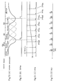
- the time to detect the PM means that time when the intake pressure sensor 17 is generating the output to indicate the pressure condition at the suction stroke of the first cylinder as shown in the timing chart of Fig. 15(A) with the X-axis representing crank angles, in which the top dead center (TDC) of the first cylinder is taken as the reference point O°.
- the detecting of the output PM is, as apparent from the timing chart of Fig. 15(A), started at any point during the period when the curve drawn in a solid line showing the PM of the first cylinder is largely depressed (between around 0° CA and 360° CA). In the present embodiment, at about 160° CA. If it is judged at the present step 700 that the crank angle is about 160° CA, and A/D conversion process of the output of the intake pressure sensor 17 is started in the next step 710, and a series of processes are started such that the output of the intake pressure sensor 17 is A/D converted in the input port 34 and its value PMAD (Fig. 15(B)) is temporarily stored in a buffer.
- the step 720 is for judgment whether or not it is the time for detecting the output TA of the throttle-opening sensor 16.
- the timing is similar to the above time for detecting the PM, in synchronism with the crank angle, and the sampling is carried out, as shown in Fig. 15(D), at shorter intervals of periods than that for detecting of the PM.
- Fig. 15(D) an example where four sampling times are carried out at equal intervals between 0° CA to 720° CA is shown, and in Fig.
- the dotted line indicates the analog output TA of the throttle-opening sensor 16 and the solid line indicates its A/D converted value TAAD.
- the throttle opening TA varying during the period from the first detecting the PMAD to he second detecting. If it is judged to be the time for detecting the TA in the step 720, then the next step 730 is followed and there an A/D conversion of the TA is started. Otherwise, the present routine is ended and another routine is executed.
- Fig. 14(B) indicates the main routine of the present embodiment which determines the fuel amount to be supplied by injection to the internal combustion engine 10.
- This routine is repeatedly executed by the CPU 31 at intervals of predetermined periods.
- the CPU 31 enters into the processing in this routine, it is judged in the step 800 whether or not the A/D conversion of the suction pipe pressure PM (a series of processing started in the above described step 710) has been finished and the newest PM value has been detected. If, at this step, it is judged that the A/D conversion of the newest PM has not been finished, the routine advances to the step 830 (to be described later), and if the A/D conversion is judged to have been finished the process in the next step 810 is executed.
- the A/D converted value of the output PM of the intake pressure sensor 17, PMAD is computed in the CPU 31. And based on these two values, i.e., the A/D converted value, PMAD, and the engine speed NE of the internal combustion engine 10 at that time, a reference fuel injection amount TPPM (the period during which the fuel injection valve 13 is opened) is computed in step 820. That is, the TPPM is computed at every 160° CA of the crank angle (Fig. 15(0).
- the next steps 830 and 840 are for executing similar processes as executed in the steps 800 and 810, that is, it is judged whether or not the detecting of the throttle opening TA at the step 730 in Fig.
- step 830 the step 880 (to be described later) is executed. And, if it has already been finished, then computation of the A/D converted value of the TA, TAAD (Fig. 15(D)) is executed in the CPU 31 (step 840). Then, based on the TAAD and the present engine speed NE of the internal combustion engine 10, a correction value for the reference fuel injection amount TP, TPTA, is computed through the processing in the next step 850, and the same is stored in the RAM 33. These situations are represented in Figs. 15(D) and (E).
- the above mentioned TPPM and the TPTA in the present step may be obtained either through actual computation or, in order to speed up the operation, through retrieval from a table which has been stored in the ROM 32 in advance.
- the next step 860 it is judged whether or not the TPTA computed in the step 850 is of the timing immediately before the A/D conversion of the PM was carried out. As shown in Figs. 15(B) and (D), the PMAD is computed for each 720° CA and the TAAD is computed for each 180° CA, and so, it is judged whether or not the above TPTA has been computed based on the TAAD.
- the routine advances to the step 880.
- the relationship between the TPTA and TPTAB is indicated in Fig. 15(E), in which the solid line indicates the TPTA and the dotted line indicates the TPTAB.
- the value assigned to the TPTAB is not necessarily from the time immediately before the computation of the PMAD. It is enough if a TPTA value substantially coincident with the PMAD is assigned to the TPTAB. That TPTA occurring immediately after the computation of the PMAD, for example, may be applicable.
- the steps 880 and 890 are for computing the fuel injection period TP.
- the value TP is calculated from the newest value of TPPM and values TPTAB and TPTA by the formula: that is the value of TPPM is provided with correction by the value (TPTA - TATAB) which is calculated at the step 880.
- the TPTAB is the value that was calculated immediately before the TPPM was calculated as described in the foregoing, and so, the influence of the throttle opening TA on the fuel injection period (TPTAB) should have already been included in the value of TPPM.
- the opening of the throttle valve 12 is regulated in either the opening or closing direction after the TPPM was calculated, the suction pipe pressure PM will naturally vary, but the variation in the PM cannot be calculated until another crank angle (160° CA) is reached. Therefore, to provide the necessary information on the fuel injection period TP while the detection of the PM is impossible, the difference between the TPTA, which has been calculated from the present throttle opening TA, and the TPTAB is computed. In other words, the change in the fuel injection period due to change in the throttle opening TA as compared with the value at the time when the computation of the TPPM was made is computed. This value is added to the TPPM and thereby the fuel injection period TP (Fig. 15(F)) required by the internal combustion engine 10 is computed.
- the shaded portion in Fig. 15(E) represents the correction width for the fuel injection period due to the change in the throttle opening TA.
- the thus computed TP is then provided in the step 900 with compensation which is known, namely, the same is multiplied by a compensation factor K such as feedback compensation according to the output of the oxygen sensor 19 for extending compensation at the time of low temperature according to the output of the water temperature sensor 18.
- a compensation factor K such as feedback compensation according to the output of the oxygen sensor 19 for extending compensation at the time of low temperature according to the output of the water temperature sensor 18.
- the superscript given to each TP in Fig. 15(F) represents the cylinder number for which the fuel injection valve 13 is opened for the period TP.
- the values of the TPs from that whose superscript is 3 (the second one from the left side of the drawing) to that whose superscript is 3 (the third one from the right side of the drawing) are computed based on the value of the TPPM which is shown to the left on Fig. 15(C).
- the electronic fuel injection control of each of the third and fourth embodiments detects the suction pipe pressure PM in synchronism with the predetermined crank angle with the use of the single intake pressure sensor 17 provided in the suction pipe 11 of only one cylinder of the independent cylinder type internal combustion engine 10 on the downstream side of its throttle valve 12 shown in Fig. 2.
- the apparatus constantly detects the opening of the throttle valve at intervals of predetermined periods of time, and thereby, if there are some periods during which detection of the suction pipe pressure PM is impossible, provides the required fuel injection periods corrected with great accuracy by the suction pipe pressure value PM computed based on the changes in the opening of the throttle valve 12, which the apparatus is adapted to continually detect at intervals of predetermined periods T.
- the internal combustion engine 10 is provided with an optimum amount of fuel supply for each cylinder and thereby enabled to fully exhibit good response that is characteristic of the independent cylinder type internal combustion engine.
- the detection of the opening TA of the throttle valve 12 is carried out at intervals of predetermined periods of time, and the apparatus can compute the fuel injection amount with constant accuracy even if the internal combustion engine 10 greatly varies in speeds from low number to high number of revolutions. This is an advantageous feature specifically for the internal combustion engine system which is mounted on a vehicle which has a wide variety of engine speeds.
Applications Claiming Priority (8)
| Application Number | Priority Date | Filing Date | Title |
|---|---|---|---|
| JP252758/84 | 1984-11-29 | ||
| JP25275884A JPS61132751A (ja) | 1984-11-29 | 1984-11-29 | 電子制御燃料噴射装置 |
| JP275530/84 | 1984-12-28 | ||
| JP275531/84 | 1984-12-28 | ||
| JP59275529A JPH0742891B2 (ja) | 1984-12-28 | 1984-12-28 | 吸気管圧力検出装置 |
| JP275529/84 | 1984-12-28 | ||
| JP59275530A JPH0742892B2 (ja) | 1984-12-28 | 1984-12-28 | 吸入空気量検出装置 |
| JP27553184A JPH066923B2 (ja) | 1984-12-28 | 1984-12-28 | 電子制御燃料噴射装置 |
Publications (3)
| Publication Number | Publication Date |
|---|---|
| EP0183265A2 true EP0183265A2 (fr) | 1986-06-04 |
| EP0183265A3 EP0183265A3 (en) | 1989-02-22 |
| EP0183265B1 EP0183265B1 (fr) | 1991-01-30 |
Family
ID=27478271
Family Applications (1)
| Application Number | Title | Priority Date | Filing Date |
|---|---|---|---|
| EP85115101A Expired - Lifetime EP0183265B1 (fr) | 1984-11-29 | 1985-11-28 | Appareil pour la détection de pression dans une conduite d'aspiration |
Country Status (3)
| Country | Link |
|---|---|
| US (1) | US4644784A (fr) |
| EP (1) | EP0183265B1 (fr) |
| DE (1) | DE3581601D1 (fr) |
Cited By (1)
| Publication number | Priority date | Publication date | Assignee | Title |
|---|---|---|---|---|
| WO2003038262A1 (fr) * | 2001-10-31 | 2003-05-08 | Yamaha Hatsudoki Kabushiki Kaisha | Dispositif de detection de pression atmospherique d'un moteur a quatre temps et procede de detection de pression atmospherique |
Families Citing this family (7)
| Publication number | Priority date | Publication date | Assignee | Title |
|---|---|---|---|---|
| US4974563A (en) * | 1988-05-23 | 1990-12-04 | Toyota Jidosha Kabushiki Kaisha | Apparatus for estimating intake air amount |
| JPH08270492A (ja) * | 1995-03-30 | 1996-10-15 | Ford Motor Co | 電子機関制御装置 |
| DE19731420A1 (de) * | 1997-07-22 | 1999-01-28 | Bosch Gmbh Robert | Vorrichtung zur Erfassung des Drucks und der Temperatur im Saugrohr einer Brennkraftmaschine und Verfahren zu ihrer Herstellung |
| JP3702777B2 (ja) * | 2000-11-22 | 2005-10-05 | 国産電機株式会社 | 多気筒内燃機関用吸気負圧検出装置及び吸気負圧検出用切換バルブ |
| JP4614104B2 (ja) * | 2006-10-16 | 2011-01-19 | 株式会社デンソー | 内燃機関の吸入空気量検出装置 |
| US9810171B2 (en) * | 2013-12-03 | 2017-11-07 | Ford Global Technologies, Llc | Method for determining an offset of a manifold pressure sensor |
| EP3882452B1 (fr) * | 2020-03-18 | 2024-05-08 | Volvo Car Corporation | Procédé de détection de fuite de soupape d'un moteur à combustion |
Citations (3)
| Publication number | Priority date | Publication date | Assignee | Title |
|---|---|---|---|---|
| US4359993A (en) * | 1981-01-26 | 1982-11-23 | General Motors Corporation | Internal combustion engine transient fuel control apparatus |
| JPS5927234A (ja) * | 1982-08-06 | 1984-02-13 | Suzuki Motor Co Ltd | 吸気管圧力検出装置 |
| EP0160949A2 (fr) * | 1984-05-07 | 1985-11-13 | Toyota Jidosha Kabushiki Kaisha | Méthode et appareil de commande du rapport air-carburant dans un moteur à combustion interne à injection séquentielle |
Family Cites Families (7)
| Publication number | Priority date | Publication date | Assignee | Title |
|---|---|---|---|---|
| JPS5139056Y2 (fr) * | 1972-06-07 | 1976-09-24 | ||
| JPS5420203A (en) * | 1977-07-15 | 1979-02-15 | Hitachi Ltd | Combustion control equipment of engine |
| JPS5651050U (fr) * | 1979-09-27 | 1981-05-07 | ||
| JPS5810137A (ja) * | 1981-07-13 | 1983-01-20 | Nippon Denso Co Ltd | 内燃機関制御方法 |
| JPS5888436A (ja) * | 1981-11-19 | 1983-05-26 | Honda Motor Co Ltd | 吸気温度による補正機能を有する内燃エンジンの空燃比補正装置 |
| JPS58206834A (ja) * | 1982-05-28 | 1983-12-02 | Honda Motor Co Ltd | 過給機を備える内燃エンジンの燃料供給制御方法 |
| JPS59183040A (ja) * | 1983-04-04 | 1984-10-18 | Toyota Motor Corp | 内燃機関の燃料供給量制御装置 |
-
1985
- 1985-11-27 US US06/802,459 patent/US4644784A/en not_active Expired - Lifetime
- 1985-11-28 EP EP85115101A patent/EP0183265B1/fr not_active Expired - Lifetime
- 1985-11-28 DE DE8585115101T patent/DE3581601D1/de not_active Expired - Lifetime
Patent Citations (3)
| Publication number | Priority date | Publication date | Assignee | Title |
|---|---|---|---|---|
| US4359993A (en) * | 1981-01-26 | 1982-11-23 | General Motors Corporation | Internal combustion engine transient fuel control apparatus |
| JPS5927234A (ja) * | 1982-08-06 | 1984-02-13 | Suzuki Motor Co Ltd | 吸気管圧力検出装置 |
| EP0160949A2 (fr) * | 1984-05-07 | 1985-11-13 | Toyota Jidosha Kabushiki Kaisha | Méthode et appareil de commande du rapport air-carburant dans un moteur à combustion interne à injection séquentielle |
Non-Patent Citations (2)
| Title |
|---|
| PATENT ABSTRACTS OF JAPAN * |
| PATENT ABSTRACTS OF JAPAN vol.8 no.121 (P-278) (1558) 7th June 1984; & JP -A- 59 027 234 * |
Cited By (2)
| Publication number | Priority date | Publication date | Assignee | Title |
|---|---|---|---|---|
| WO2003038262A1 (fr) * | 2001-10-31 | 2003-05-08 | Yamaha Hatsudoki Kabushiki Kaisha | Dispositif de detection de pression atmospherique d'un moteur a quatre temps et procede de detection de pression atmospherique |
| US6983646B2 (en) | 2001-10-31 | 2006-01-10 | Yamaha Hatsudoki Kabushiki Kaisha | Atmospheric pressure detection device of four-stroke engine and method of detecting atmospheric pressure |
Also Published As
| Publication number | Publication date |
|---|---|
| DE3581601D1 (de) | 1991-03-07 |
| EP0183265B1 (fr) | 1991-01-30 |
| US4644784A (en) | 1987-02-24 |
| EP0183265A3 (en) | 1989-02-22 |
Similar Documents
| Publication | Publication Date | Title |
|---|---|---|
| EP0589517B1 (fr) | Procédé pour la prédiction de l'écoulement d'air dans un cylindre | |
| US5016591A (en) | System and method for controlling a combustion state in a multi-cylinder engine for a vehicle | |
| US4886030A (en) | Method of and system for controlling fuel injection rate in an internal combustion engine | |
| US5224452A (en) | Air-fuel ratio control system of internal combustion engine | |
| EP0115868A2 (fr) | Dispositif et procédé de commande d'alimentation en carburant d'un moteur à combustion interne | |
| US4440119A (en) | Electronic fuel injecting method and device for internal combustion engine | |
| US4471742A (en) | Fuel supply control method for an internal combustion engine equipped with a supercharger | |
| US4499881A (en) | Method and apparatus for controlling internal combustion engines | |
| US4683857A (en) | Method for controlling air/fuel ratio | |
| EP0314081B1 (fr) | Système de commande de moteur à combustion améliorée pour les régimes transitoires | |
| US5058550A (en) | Method for determining the control values of a multicylinder internal combustion engine and apparatus therefor | |
| US4469074A (en) | Electronic control for internal combustion engine | |
| US4463732A (en) | Electronic controlled non-synchronous fuel injecting method and device for internal combustion engines | |
| US5569847A (en) | Air-fuel ratio estimator for internal combustion engine | |
| US4589390A (en) | Air-fuel ratio feedback control method for internal combustion engines | |
| US4644784A (en) | Suction pipe pressure detection apparatus | |
| US4469073A (en) | Electronic fuel injecting method and device for internal combustion engine | |
| US4725954A (en) | Apparatus and method for controlling fuel supply to internal combustion engine | |
| US4462375A (en) | Method and apparatus for controlling fuel supply of an internal combustion engine | |
| US4901699A (en) | System for controlling a fuel injection quantity and method therefor | |
| US4702213A (en) | Method for controlling air/fuel ratio | |
| US4520784A (en) | Method of and apparatus for controlling fuel injection | |
| JP2929744B2 (ja) | 内燃機関の空燃比制御装置 | |
| JPS61116051A (ja) | 機関制御用信号の処理方法 | |
| US4432322A (en) | Method and system for controlling ignition timing in a multicylinder internal combustion engine |
Legal Events
| Date | Code | Title | Description |
|---|---|---|---|
| PUAI | Public reference made under article 153(3) epc to a published international application that has entered the european phase |
Free format text: ORIGINAL CODE: 0009012 |
|
| AK | Designated contracting states |
Kind code of ref document: A2 Designated state(s): DE FR GB |
|
| PUAL | Search report despatched |
Free format text: ORIGINAL CODE: 0009013 |
|
| AK | Designated contracting states |
Kind code of ref document: A3 Designated state(s): DE FR GB |
|
| 17P | Request for examination filed |
Effective date: 19890714 |
|
| 17Q | First examination report despatched |
Effective date: 19890913 |
|
| GRAA | (expected) grant |
Free format text: ORIGINAL CODE: 0009210 |
|
| AK | Designated contracting states |
Kind code of ref document: B1 Designated state(s): DE FR GB |
|
| ET | Fr: translation filed | ||
| REF | Corresponds to: |
Ref document number: 3581601 Country of ref document: DE Date of ref document: 19910307 |
|
| PLBE | No opposition filed within time limit |
Free format text: ORIGINAL CODE: 0009261 |
|
| STAA | Information on the status of an ep patent application or granted ep patent |
Free format text: STATUS: NO OPPOSITION FILED WITHIN TIME LIMIT |
|
| 26N | No opposition filed | ||
| REG | Reference to a national code |
Ref country code: GB Ref legal event code: 746 Effective date: 19940523 |
|
| REG | Reference to a national code |
Ref country code: FR Ref legal event code: D6 |
|
| PGFP | Annual fee paid to national office [announced via postgrant information from national office to epo] |
Ref country code: FR Payment date: 20011113 Year of fee payment: 17 |
|
| PGFP | Annual fee paid to national office [announced via postgrant information from national office to epo] |
Ref country code: GB Payment date: 20011128 Year of fee payment: 17 |
|
| PGFP | Annual fee paid to national office [announced via postgrant information from national office to epo] |
Ref country code: DE Payment date: 20011210 Year of fee payment: 17 |
|
| REG | Reference to a national code |
Ref country code: GB Ref legal event code: IF02 |
|
| PG25 | Lapsed in a contracting state [announced via postgrant information from national office to epo] |
Ref country code: GB Free format text: LAPSE BECAUSE OF NON-PAYMENT OF DUE FEES Effective date: 20021128 |
|
| PG25 | Lapsed in a contracting state [announced via postgrant information from national office to epo] |
Ref country code: DE Free format text: LAPSE BECAUSE OF NON-PAYMENT OF DUE FEES Effective date: 20030603 |
|
| GBPC | Gb: european patent ceased through non-payment of renewal fee | ||
| PG25 | Lapsed in a contracting state [announced via postgrant information from national office to epo] |
Ref country code: FR Free format text: LAPSE BECAUSE OF NON-PAYMENT OF DUE FEES Effective date: 20030731 |
|
| REG | Reference to a national code |
Ref country code: FR Ref legal event code: ST |