EP0183157B1 - Gas/Luft-Verbundregler - Google Patents
Gas/Luft-Verbundregler Download PDFInfo
- Publication number
- EP0183157B1 EP0183157B1 EP85114593A EP85114593A EP0183157B1 EP 0183157 B1 EP0183157 B1 EP 0183157B1 EP 85114593 A EP85114593 A EP 85114593A EP 85114593 A EP85114593 A EP 85114593A EP 0183157 B1 EP0183157 B1 EP 0183157B1
- Authority
- EP
- European Patent Office
- Prior art keywords
- gas
- abutment
- air
- levers
- lever
- Prior art date
- Legal status (The legal status is an assumption and is not a legal conclusion. Google has not performed a legal analysis and makes no representation as to the accuracy of the status listed.)
- Expired - Lifetime
Links
- 230000007246 mechanism Effects 0.000 claims abstract description 7
- 238000010304 firing Methods 0.000 claims abstract description 4
- 230000005484 gravity Effects 0.000 claims abstract 4
- 238000009434 installation Methods 0.000 claims abstract 2
- 238000006073 displacement reaction Methods 0.000 claims description 4
- 239000012528 membrane Substances 0.000 description 22
- 238000002485 combustion reaction Methods 0.000 description 13
- 239000002131 composite material Substances 0.000 description 12
- 230000005540 biological transmission Effects 0.000 description 7
- 230000006835 compression Effects 0.000 description 4
- 238000007906 compression Methods 0.000 description 4
- 230000008859 change Effects 0.000 description 3
- 150000001875 compounds Chemical class 0.000 description 3
- 230000009471 action Effects 0.000 description 2
- 230000001419 dependent effect Effects 0.000 description 2
- 239000000203 mixture Substances 0.000 description 2
- 230000008901 benefit Effects 0.000 description 1
- 230000033228 biological regulation Effects 0.000 description 1
- 238000006243 chemical reaction Methods 0.000 description 1
- 238000010276 construction Methods 0.000 description 1
- 238000010586 diagram Methods 0.000 description 1
- 230000000694 effects Effects 0.000 description 1
- 238000000034 method Methods 0.000 description 1
- 230000002093 peripheral effect Effects 0.000 description 1
- 230000008569 process Effects 0.000 description 1
- 230000001681 protective effect Effects 0.000 description 1
- 238000000926 separation method Methods 0.000 description 1
Images


Classifications
-
- G—PHYSICS
- G01—MEASURING; TESTING
- G01L—MEASURING FORCE, STRESS, TORQUE, WORK, MECHANICAL POWER, MECHANICAL EFFICIENCY, OR FLUID PRESSURE
- G01L15/00—Devices or apparatus for measuring two or more fluid pressure values simultaneously
-
- F—MECHANICAL ENGINEERING; LIGHTING; HEATING; WEAPONS; BLASTING
- F23—COMBUSTION APPARATUS; COMBUSTION PROCESSES
- F23N—REGULATING OR CONTROLLING COMBUSTION
- F23N1/00—Regulating fuel supply
- F23N1/02—Regulating fuel supply conjointly with air supply
- F23N1/027—Regulating fuel supply conjointly with air supply using mechanical means
Definitions
- the invention relates to a gas / air composite controller according to the preamble of patent claim 1.
- a gas / air composite controller for a gas burner system in which between two levers arranged in parallel to each other, each connected to the membrane of a pressure gauge connected to the gas supply line or the air supply line, an in Longitudinal direction of the lever displaceable abutment is arranged.
- the position of the abutment is determined by a cam, the position of which can in turn be changed by means of a drive which responds to the output signal of a calorimetric device checking the composition of the gas / air mixture.
- the displaceable abutment of the gas / air composite regulator known from US-A-2 193 240 enables a corresponding change and thus also adjustment of the gas / air ratio by changing the transmission ratio between the levers coupled by the abutment.
- the disadvantage of this arrangement is that, especially when the abutment is already in its basic position near the end of one of the two levers, a strong variation in the transmission ratio and thus the gas / air ratio is no longer possible if this change is a Moving the abutment towards the end of a lever requires.
- the invention has for its object to design a gas / air composite controller of the type mentioned so that it allows such a variation of the gas / air ratio, which is essentially independent of the basic setting, within wide limits.
- the permanently adjustable abutment is used to set the optimal gas / air ratio under normal conditions.
- the other abutment provided with the motor drive can be in its central position.
- the other abutment then allows both a very large increase and decrease in the transmission ratio of the lever mechanism and thus the gas / air ratio selected by the fixedly adjustable abutment for normal conditions by moving it out of its central position.
- the use of an additional lever and additional abutment means no significant additional effort, especially since the separation of the abutment into a fixedly adjustable abutment and an abutment provided with a motor drive leads to structural simplifications.
- the fixedly adjustable abutment is attached to a slide which is displaceably mounted on one of the levers and which engages with a screw spindle mounted parallel to the lever.
- the mounting of a slide bearing the abutment on the lever results in a very stable arrangement of the abutment in connection with a very sensitive adjustability.
- the abutment provided with the motor drive can advantageously be attached to the end of an arm which is pivotably mounted on an actuator which is displaceably mounted in the longitudinal direction of the arm.
- the particular advantage of this arrangement is that the motor drive acts on a linearly displaceable member and does not need to follow any other movements. Since the position of the abutment is only important for the action of the abutment, it does not matter how long the arm on which the abutment is located and where its pivot point is arranged. This is particularly true when the abutment is formed by a rotatably mounted roller, because then because of the circular peripheral surface of the rollers, the angular position of the rollers with respect to the adjacent levers is also irrelevant.
- the actuator is formed by a displaceably mounted toothed rack with which the drive pinion of an electric motor is in engagement.
- a toothed wheel fixed on the shaft of a potentiometer is in engagement with the toothed rack.
- the potentiometer forms a position indicator indicating the position of the rack and thus the abutment.
- Such a position transmitter is particularly necessary if, depending on the control variable, for example the air pressure or the combustion chamber back pressure, a displacement of the abutment from the central position is required by a certain amount.
- a particularly compact construction of the gas / Air composite controller can be achieved in a further embodiment of the invention in that the intermediate lever is fork-shaped and has legs adjacent to the adjacent levers, on which the abutments arranged on the side of the levers are supported.
- the fork-shaped design of the intermediate lever enables all levers to be arranged at a very short distance from one another, because if the outer levers are strongly inclined relative to the intermediate lever, the ends of the outer levers can enter between the legs of the intermediate lever, so that the levers can overlap.
- the abutments are formed by rollers, which face flat surfaces on the levers as raceways, it is advantageous if at least one of the levers is pivotally mounted about an axis substantially parallel to its longitudinal direction, because it then under the influence of the forces to be transferred automatically flat against the cylindrical circumference of the roll.
- the gas firing system which is shown only schematically in FIG. 1 and is known from US-A-2 193 240, comprises a burner 1, to which a gas supply line 2 and an air supply line 3 are connected, and which shows a new type of action on a valve in the gas supply line.
- a membrane pressure meter 4 or 5 is connected via a line 24 or 25 in such a way that their membranes 6 and 7 are acted upon on opposite sides.
- a lever 9, which extends essentially parallel to the membrane 6, is in drive connection with the membrane 6 of the gas pressure meter 4 via a pressure pin 8.
- a second lever 11 is in drive connection with the membrane 7 of the air pressure meter 5 via a pressure pin 10, which also extends essentially parallel to the membrane 7 of the air pressure meter 5 and thus also in its central position parallel to the first lever 9.
- the two levers 9, 11 arranged essentially parallel to one another in a common plane are further coupled to one another by an abutment 12, against which the levers 9, 11 bear with their sides opposite the pressure pins 8, 10.
- the membrane 6 of the gas pressure meter 4 is also provided on its side exposed to the gas pressure with a plunger 13, at the end of which there is the closure piece 14 of a valve arranged in the gas supply line 2 15 is located.
- the closure piece 14 is loaded on the side facing away from the valve 15 by a helical compression spring 16.
- the levers 9, 11 coupled to the diaphragms 6, 7 of the pressure gauges 4, 5 together with the abutment 12 form a ratio setting mechanism 17.
- This ratio is determined by the position of the abutment 12 between the levers 9 and 11, the relative lengths of which defined by the position of the abutment 12 result in a transmission ratio which can be changed by moving the abutment.
- the valve 15 in the gas supply line 2 is open when the pressure acting on the membrane 7 of the air pressure meter 5 is greater by an amount determined by the transmission ratio than the pressure acting on the membrane 6 of the gas pressure meter 4 and the counter pressure of the helical compression spring 16 overcomes.
- the optimum pressure ratio for a specific gas combustion system under normal operating conditions can be set by moving the abutment 12.
- the normal conditions in which the abutment 12 was adjusted are not always present.
- the optimal gas / air ratio is highly dependent on the air temperature.
- the air temperature is subject to considerable fluctuations, so that it proves expedient to modify the gas / air ratio as a function of the air temperature.
- the gas firing system shown in Fig. 1 offers such a possibility. It comprises a temperature sensor 18 arranged in the gas supply line 3, which supplies a signal characteristic of the air temperature to a control device 19.
- the control unit 19 generates an output signal, which is dependent on the air temperature, for a drive 20 for a rectilinearly displaceable actuator 21, on the end of which, facing the ratio setting mechanism 17, an arm 22 is articulated, on the free end of which the abutment 12 is located.
- the drive 20 effects a Ver push the abutment 12 against the position selected for normal conditions, by which the gas / air ratio is changed in such a way that the gas / air ratio required for optimal combustion is set even when the air temperatures deviate from the normal temperature.
- the actuator 21 transmits its approximately parallel movement to the levers 9, 11 via the arm 22 to the abutment 12, while the pivotable connection between the actuator 21 and arm 22 allows the abutment 12 to the pivoting movements of the levers 9, 11 consequences.
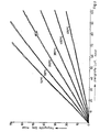
- FIG. 2 illustrates the characteristic field of the gas / air composite controller of a gas combustion system according to FIG. 1.
- the different, essentially straight curves correspond to different gas / air ratios determined by the position of the abutment for the air temperatures written on the individual curves.
- the adjustment paths for the abutment assigned to the different temperatures are determined in the usual way by means of the control unit 19.
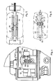
- FIGS. 3 to 6 show in detail the structure of an embodiment of the gas / air composite controller according to the invention, which is particularly suitable for use in a gas combustion system, as shown in FIG. 1.
- the gas / air compound controller shown in FIGS. 3 to 6 comprises two diaphragm pressure gauges, namely a gas pressure gauge 4 with a diaphragm 6 and an air pressure gauge 5 with a diaphragm 7.
- the upper one in FIG the membrane 7 downwardly limited chamber of the air pressure meter 5 is provided with a connecting piece 31 which enables the connection to the air supply line of a gas combustion system.
- the ratio setting mechanism arranged between the membranes 6, 7 of the two membrane pressure gauges 4, 5 comprises three levers, namely the lever 9 coupled to the membrane 6 of the gas pressure gauge 4 via a pressure pin 8 and the lever 9 via a pressure pin 10 to the membrane 7 of the air pressure meter 5 coupled lever 11 and an intermediate lever 33. Between the paired opposite levers are abutments 34 and 35, which are formed by rollers.
- the rollers arranged between the lever 11 connected to the diaphragm 7 of the air pressure meter 5 and the intermediate lever 33 are formed by small ball bearings which are fastened to trunnions 36 which protrude from the side surfaces of a slide 37 slidably mounted on the bar-shaped lever 11.
- the carriage 37 engages around the lever 11 in a U-shape and is guided in the region of its crosspiece on a screw spindle 38 which is mounted in lugs 39, 40 at the ends of the lever 11, but is rotatably but axially immovable.
- the screw spindle 38 protrudes beyond the end of the lever 11, on which this lever is pivotably mounted on a pin 41, and carries a handle 42 there.
- This handle allows the slide 37 with the abutment 35 in the longitudinal direction by turning the threaded spindle 38 to move the lever and thus to change the gear ratio with respect to the intermediate lever 33.
- the rollers serving as abutments 35 are located on both sides of the lever 11, so that the intermediate lever 33 must have treads lying on both sides next to the lever 11. Accordingly, the intermediate lever 33 is fork-shaped, so that the lever 11 can engage between the legs of the fork-shaped intermediate lever 33. In this way, an extremely compact height is achieved.
- the abutment 34 which is arranged between the lever 9 coupled to the diaphragm 6 of the gas pressure meter 4 and the intermediate lever 33, is located at the end of a pivotably mounted arm 45, the free end of which is again fork-shaped and three ball bearings 47, 48 on a journal 46 carries, of which the middle, arranged between the legs 49 of the fork ball bearing 47 is seated on the lever 9, while the ball bearings 48 arranged outside the fork legs 49 rest on the legs of the fork-shaped intermediate lever 33.
- an actuator 50 is used in the form of a rack which is displaceable in a tube 51 fixed to the housing in the direction of the lever, but is non-rotatably mounted about its axis and on whose end facing the lever, the arm 45 is pivotally attached to the abutment 34.
- An electric motor 52 is used to drive the rack, on whose output shaft there is a pinion 53 which engages in the toothing 54 of the actuator 50.
- a gear 55 which is located on the drive shaft of a potentiometer 56, is still engaged with this pinion 53 and consequently also indirectly with the actuator 50.
- a limit switch 57 cooperates with the end of the toothed rack and limits the displacement path of the actuator 50.
- the lever 9 cooperating with the gas pressure meter 4 is pivotally mounted at the end of a pin 58 which is rotatably mounted in the housing 43 and extends essentially parallel to the direction of the lever 9 articulated thereon.
- the mounting of the lever 9, which can be pivoted essentially about its longitudinal axis, ensures that its running surface bears perfectly against the lateral surface of the abutment 34 designed as a roller.
- the gas / air composite controller shown in FIGS. 3 to 6 allows the abutment 35 between the lever 11 assigned to the air pressure meter 5 and the intermediate lever 33 to be at a predetermined zero position of the motor-adjustable abutment 34 by means of the screw spindle 38 Set gas / air ratio that is optimal for the normal conditions of a gas combustion system. Otherwise, the mode of operation of the gas / air combination controller described corresponds to that of the known gas / air combination controller.
- the gas pressure acting on the membrane 6 is counteracted by the air pressure acting on the membrane 7 in accordance with the transmission ratio set on the ratio adjuster.
- the forces exerted by the pressure-loaded membranes 6, 7 have a resultant which leads to an opening of the control valve arranged below the gas membrane 6, the tappet 61 of which is connected to the membrane 6 when the resultant of the forces is the counterforce of the membrane 6 of the gas pressure meter 4 loading coil compression spring 59 exceeds.
- the force of the helical compression spring 59 must be such that it compensates for the weight of the diaphragm arrangement and the ratio adjuster in the selected basic setting of the ratio adjuster, and is adjustable for this purpose by means of an abutment 72 adjustable by a wedge 71. Individual data of this adjustment device are described in our peer-to-peer DE-A-34 43 532.8 with the title "Gas / Air Compound Controller".
- the control valve 60 is located between connections 62, 63, to which a servo system for controlling a throttle valve in the gas supply line can be connected.
- This gas / air ratio set for normal conditions can then be changed within wide limits by moving the second abutment 34, without thereby influencing the basic setting.
- the second abutment 34 is displaced by means of the motor drive formed by the electric motor 52 as a function of control signals which are supplied to the electric motor by a control device in the manner described above.
- this can be a control process or a regulation.
- the potentiometer 56 serves this purpose, the position of which determines the size of an electrical output signal which is characteristic of the position of the motor-driven abutment 34.
Landscapes
- Engineering & Computer Science (AREA)
- Chemical & Material Sciences (AREA)
- Combustion & Propulsion (AREA)
- Mechanical Engineering (AREA)
- General Engineering & Computer Science (AREA)
- Physics & Mathematics (AREA)
- General Physics & Mathematics (AREA)
- Regulation And Control Of Combustion (AREA)
- Furnace Details (AREA)
Priority Applications (1)
| Application Number | Priority Date | Filing Date | Title |
|---|---|---|---|
| AT85114593T ATE53651T1 (de) | 1984-11-29 | 1985-11-16 | Gas/luft-verbundregler. |
Applications Claiming Priority (2)
| Application Number | Priority Date | Filing Date | Title |
|---|---|---|---|
| DE19843443533 DE3443533A1 (de) | 1984-11-29 | 1984-11-29 | Gasfeuerungsanlage mit einem gas/luft-verbundregler |
| DE3443533 | 1984-11-29 |
Publications (2)
| Publication Number | Publication Date |
|---|---|
| EP0183157A1 EP0183157A1 (de) | 1986-06-04 |
| EP0183157B1 true EP0183157B1 (de) | 1990-06-13 |
Family
ID=6251477
Family Applications (1)
| Application Number | Title | Priority Date | Filing Date |
|---|---|---|---|
| EP85114593A Expired - Lifetime EP0183157B1 (de) | 1984-11-29 | 1985-11-16 | Gas/Luft-Verbundregler |
Country Status (3)
| Country | Link |
|---|---|
| EP (1) | EP0183157B1 (enExample) |
| AT (1) | ATE53651T1 (enExample) |
| DE (1) | DE3443533A1 (enExample) |
Families Citing this family (4)
| Publication number | Priority date | Publication date | Assignee | Title |
|---|---|---|---|---|
| DE3721153A1 (de) * | 1987-06-26 | 1989-01-05 | Manfred Geitner | Verfahren zur thermostatgeregelten anpassung der waermeabgabe eines waermestrahlers, sowie vorrichtung zur durchfuehrung des verfahrens |
| DE9316918U1 (de) * | 1993-11-05 | 1994-01-13 | Karl Dungs GmbH & Co, 73660 Urbach | Mehrfachstellgerät mit eingangsseitigem Regler |
| DE59502756D1 (de) * | 1995-01-30 | 1998-08-13 | Landis & Gyr Tech Innovat | Regelvorrichtung für einen Gasgebläsebrenner |
| DE102023106723A1 (de) * | 2023-03-17 | 2024-09-19 | Vaillant Gmbh | Einstellanordnung für ein Gasventil, Verfahren zur Einstellung eines universellen Gasventils eines Heizgerätes, Gasventil und Heizgerät |
Family Cites Families (6)
| Publication number | Priority date | Publication date | Assignee | Title |
|---|---|---|---|---|
| US2193240A (en) * | 1937-10-25 | 1940-03-12 | Cutler Hammer Inc | Method of and apparatus for controlling mixing of combustible gases |
| US3244008A (en) * | 1962-03-19 | 1966-04-05 | Holley Carburetor Co | Ratio sensing device |
| US3244007A (en) * | 1962-03-19 | 1966-04-05 | Holley Carburetor Co | Pressure ratio measuring device |
| DE2412720C3 (de) * | 1974-03-16 | 1979-08-30 | Gerlach-Werke Gmbh, 6650 Homburg | Vorrichtung zur Regelung des Verhältnisses der Drücke in einer Gas- und einer Luftzuleitung für eine industrielle Feuerung |
| CH593455A5 (enExample) * | 1975-09-19 | 1977-11-30 | Landis & Gyr Ag | |
| DE3039994A1 (de) * | 1980-10-23 | 1982-05-06 | Karl Dungs Gmbh & Co, 7067 Urbach | Verfahren zur einstellung von verbundreglern fuer brenner in waermeerzeugungsanlagen |
-
1984
- 1984-11-29 DE DE19843443533 patent/DE3443533A1/de active Granted
-
1985
- 1985-11-16 EP EP85114593A patent/EP0183157B1/de not_active Expired - Lifetime
- 1985-11-16 AT AT85114593T patent/ATE53651T1/de not_active IP Right Cessation
Also Published As
| Publication number | Publication date |
|---|---|
| EP0183157A1 (de) | 1986-06-04 |
| DE3443533A1 (de) | 1986-06-05 |
| DE3443533C2 (enExample) | 1991-03-07 |
| ATE53651T1 (de) | 1990-06-15 |
Similar Documents
| Publication | Publication Date | Title |
|---|---|---|
| DE2334729B2 (de) | Fliehkraftdrehzahlregler für Einspritzbrennkraftmaschinen | |
| DE3207807C2 (de) | Kraftstoff-Einspritzpumpe für einen Verbrennungsmotor | |
| EP0183157B1 (de) | Gas/Luft-Verbundregler | |
| EP0131107B1 (de) | Farbdosiereinrichtung für eine Druckmaschine | |
| DE19817977A1 (de) | Rollenführung für ein Walzgerüst | |
| DE3144173C2 (de) | Drehzahlregler für Einspritzbrennkraftmaschinen | |
| DE1601672C3 (enExample) | ||
| DE2847380C2 (de) | Druckmittelbetriebener Regler mit Rückführung, insbesondere Stellungsregler | |
| DE2824660C2 (de) | Papierschneidemaschine oder ähnliche Schneidemaschine | |
| DE1013907B (de) | Druckmittelbetriebener Regler mit Rueckfuehrung | |
| DE2300332C3 (de) | Schaltvorrichtung für unstetige Druck- oder Temperaturregler | |
| DE1951381C3 (de) | Vorrichtung zur Steuerung von Verdrängerpumpen | |
| DE2827771C2 (de) | Regeleinrichtung für Gas- oder Ölfeuerungen mit einer Verbundverstellung | |
| EP0974739A1 (de) | Koppelgetriebe für eine variable Ventilsteuerung von Brennkraftmaschinen | |
| EP0386195B1 (de) | Drahtpistole | |
| DE2412720A1 (de) | Vorrichtung zum einstellen und selbsttaetigen regeln des mischverhaeltnisses eines gas-luftgemisches | |
| DE4027574C2 (enExample) | ||
| CH366454A (de) | Regeleinrichtung | |
| EP1033559A2 (de) | Kurbeltrieb | |
| DE2514407A1 (de) | Betaetigungseinrichtung fuer ein getriebe-steuerorgan | |
| DE2324774A1 (de) | Stellantrieb | |
| DE2905799C2 (de) | Pneumatischer Stellungsregler mit Spiralmeßfeder | |
| CH670142A5 (en) | Motorised positioning drive for stopcock or regulator valve - incorporates manual override for disengagement of gears from driving spindle directly coupled to linear potentiometer | |
| DE1952215C (de) | Betätigungsvorrichtung fur eine Brenn kraftmaschine | |
| DE1803564C3 (de) | Fliehkraftregler zur Drehzahlregelung von Brennkraftmaschinen |
Legal Events
| Date | Code | Title | Description |
|---|---|---|---|
| PUAI | Public reference made under article 153(3) epc to a published international application that has entered the european phase |
Free format text: ORIGINAL CODE: 0009012 |
|
| AK | Designated contracting states |
Kind code of ref document: A1 Designated state(s): AT BE CH FR GB IT LI NL SE |
|
| 17P | Request for examination filed |
Effective date: 19860624 |
|
| 17Q | First examination report despatched |
Effective date: 19880530 |
|
| GRAA | (expected) grant |
Free format text: ORIGINAL CODE: 0009210 |
|
| AK | Designated contracting states |
Kind code of ref document: B1 Designated state(s): AT BE CH FR GB IT LI NL SE |
|
| REF | Corresponds to: |
Ref document number: 53651 Country of ref document: AT Date of ref document: 19900615 Kind code of ref document: T |
|
| ITF | It: translation for a ep patent filed | ||
| ET | Fr: translation filed | ||
| GBT | Gb: translation of ep patent filed (gb section 77(6)(a)/1977) | ||
| PLBE | No opposition filed within time limit |
Free format text: ORIGINAL CODE: 0009261 |
|
| STAA | Information on the status of an ep patent application or granted ep patent |
Free format text: STATUS: NO OPPOSITION FILED WITHIN TIME LIMIT |
|
| 26N | No opposition filed | ||
| ITTA | It: last paid annual fee | ||
| EAL | Se: european patent in force in sweden |
Ref document number: 85114593.8 |
|
| PGFP | Annual fee paid to national office [announced via postgrant information from national office to epo] |
Ref country code: GB Payment date: 19981022 Year of fee payment: 14 |
|
| PGFP | Annual fee paid to national office [announced via postgrant information from national office to epo] |
Ref country code: CH Payment date: 19981027 Year of fee payment: 14 |
|
| PGFP | Annual fee paid to national office [announced via postgrant information from national office to epo] |
Ref country code: BE Payment date: 19981104 Year of fee payment: 14 |
|
| PGFP | Annual fee paid to national office [announced via postgrant information from national office to epo] |
Ref country code: FR Payment date: 19981123 Year of fee payment: 14 |
|
| PGFP | Annual fee paid to national office [announced via postgrant information from national office to epo] |
Ref country code: SE Payment date: 19981126 Year of fee payment: 14 |
|
| PGFP | Annual fee paid to national office [announced via postgrant information from national office to epo] |
Ref country code: NL Payment date: 19981130 Year of fee payment: 14 Ref country code: AT Payment date: 19981130 Year of fee payment: 14 |
|
| PG25 | Lapsed in a contracting state [announced via postgrant information from national office to epo] |
Ref country code: GB Free format text: LAPSE BECAUSE OF NON-PAYMENT OF DUE FEES Effective date: 19991116 Ref country code: AT Free format text: LAPSE BECAUSE OF NON-PAYMENT OF DUE FEES Effective date: 19991116 |
|
| PG25 | Lapsed in a contracting state [announced via postgrant information from national office to epo] |
Ref country code: SE Free format text: LAPSE BECAUSE OF NON-PAYMENT OF DUE FEES Effective date: 19991117 |
|
| PG25 | Lapsed in a contracting state [announced via postgrant information from national office to epo] |
Ref country code: LI Free format text: LAPSE BECAUSE OF NON-PAYMENT OF DUE FEES Effective date: 19991130 Ref country code: CH Free format text: LAPSE BECAUSE OF NON-PAYMENT OF DUE FEES Effective date: 19991130 Ref country code: BE Free format text: LAPSE BECAUSE OF NON-PAYMENT OF DUE FEES Effective date: 19991130 |
|
| BERE | Be: lapsed |
Owner name: KARL DUNGS G.M.B.H. & CO. Effective date: 19991130 |
|
| PG25 | Lapsed in a contracting state [announced via postgrant information from national office to epo] |
Ref country code: NL Free format text: LAPSE BECAUSE OF NON-PAYMENT OF DUE FEES Effective date: 20000601 |
|
| GBPC | Gb: european patent ceased through non-payment of renewal fee |
Effective date: 19991116 |
|
| REG | Reference to a national code |
Ref country code: CH Ref legal event code: PL |
|
| EUG | Se: european patent has lapsed |
Ref document number: 85114593.8 |
|
| PG25 | Lapsed in a contracting state [announced via postgrant information from national office to epo] |
Ref country code: FR Free format text: LAPSE BECAUSE OF NON-PAYMENT OF DUE FEES Effective date: 20000731 |
|
| NLV4 | Nl: lapsed or anulled due to non-payment of the annual fee |
Effective date: 20000601 |
|
| REG | Reference to a national code |
Ref country code: FR Ref legal event code: ST |