EP0182955B2 - Reaktionsgefäss - Google Patents
Reaktionsgefäss Download PDFInfo
- Publication number
- EP0182955B2 EP0182955B2 EP19850100494 EP85100494A EP0182955B2 EP 0182955 B2 EP0182955 B2 EP 0182955B2 EP 19850100494 EP19850100494 EP 19850100494 EP 85100494 A EP85100494 A EP 85100494A EP 0182955 B2 EP0182955 B2 EP 0182955B2
- Authority
- EP
- European Patent Office
- Prior art keywords
- reaction vessel
- vessel according
- chamber
- reaction
- liquid
- Prior art date
- Legal status (The legal status is an assumption and is not a legal conclusion. Google has not performed a legal analysis and makes no representation as to the accuracy of the status listed.)
- Expired - Lifetime
Links
- 239000007788 liquid Substances 0.000 claims abstract description 29
- 239000010802 sludge Substances 0.000 claims abstract description 18
- 239000002028 Biomass Substances 0.000 claims abstract description 12
- 238000005192 partition Methods 0.000 claims abstract 2
- 239000000203 mixture Substances 0.000 claims description 12
- 238000004062 sedimentation Methods 0.000 claims description 10
- VNWKTOKETHGBQD-UHFFFAOYSA-N methane Chemical compound C VNWKTOKETHGBQD-UHFFFAOYSA-N 0.000 claims description 8
- 230000002093 peripheral effect Effects 0.000 claims description 2
- 239000002562 thickening agent Substances 0.000 claims 7
- 239000002351 wastewater Substances 0.000 claims 1
- 238000000926 separation method Methods 0.000 abstract description 3
- 239000007789 gas Substances 0.000 description 5
- 238000007872 degassing Methods 0.000 description 4
- 238000000855 fermentation Methods 0.000 description 3
- 230000004151 fermentation Effects 0.000 description 3
- CURLTUGMZLYLDI-UHFFFAOYSA-N Carbon dioxide Chemical compound O=C=O CURLTUGMZLYLDI-UHFFFAOYSA-N 0.000 description 2
- 238000012544 monitoring process Methods 0.000 description 2
- XLYOFNOQVPJJNP-UHFFFAOYSA-N water Substances O XLYOFNOQVPJJNP-UHFFFAOYSA-N 0.000 description 2
- 229910000831 Steel Inorganic materials 0.000 description 1
- 229910002092 carbon dioxide Inorganic materials 0.000 description 1
- 239000001569 carbon dioxide Substances 0.000 description 1
- 239000007795 chemical reaction product Substances 0.000 description 1
- 238000004891 communication Methods 0.000 description 1
- 238000012423 maintenance Methods 0.000 description 1
- 230000001105 regulatory effect Effects 0.000 description 1
- 230000002787 reinforcement Effects 0.000 description 1
- 239000007787 solid Substances 0.000 description 1
- 239000010959 steel Substances 0.000 description 1
Images

Classifications
-
- C—CHEMISTRY; METALLURGY
- C02—TREATMENT OF WATER, WASTE WATER, SEWAGE, OR SLUDGE
- C02F—TREATMENT OF WATER, WASTE WATER, SEWAGE, OR SLUDGE
- C02F3/00—Biological treatment of water, waste water, or sewage
- C02F3/28—Anaerobic digestion processes
- C02F3/2866—Particular arrangements for anaerobic reactors
- C02F3/2873—Particular arrangements for anaerobic reactors with internal draft tube circulation
-
- C—CHEMISTRY; METALLURGY
- C12—BIOCHEMISTRY; BEER; SPIRITS; WINE; VINEGAR; MICROBIOLOGY; ENZYMOLOGY; MUTATION OR GENETIC ENGINEERING
- C12M—APPARATUS FOR ENZYMOLOGY OR MICROBIOLOGY; APPARATUS FOR CULTURING MICROORGANISMS FOR PRODUCING BIOMASS, FOR GROWING CELLS OR FOR OBTAINING FERMENTATION OR METABOLIC PRODUCTS, i.e. BIOREACTORS OR FERMENTERS
- C12M21/00—Bioreactors or fermenters specially adapted for specific uses
- C12M21/04—Bioreactors or fermenters specially adapted for specific uses for producing gas, e.g. biogas
-
- C—CHEMISTRY; METALLURGY
- C12—BIOCHEMISTRY; BEER; SPIRITS; WINE; VINEGAR; MICROBIOLOGY; ENZYMOLOGY; MUTATION OR GENETIC ENGINEERING
- C12M—APPARATUS FOR ENZYMOLOGY OR MICROBIOLOGY; APPARATUS FOR CULTURING MICROORGANISMS FOR PRODUCING BIOMASS, FOR GROWING CELLS OR FOR OBTAINING FERMENTATION OR METABOLIC PRODUCTS, i.e. BIOREACTORS OR FERMENTERS
- C12M23/00—Constructional details, e.g. recesses, hinges
- C12M23/36—Means for collection or storage of gas; Gas holders
-
- C—CHEMISTRY; METALLURGY
- C12—BIOCHEMISTRY; BEER; SPIRITS; WINE; VINEGAR; MICROBIOLOGY; ENZYMOLOGY; MUTATION OR GENETIC ENGINEERING
- C12M—APPARATUS FOR ENZYMOLOGY OR MICROBIOLOGY; APPARATUS FOR CULTURING MICROORGANISMS FOR PRODUCING BIOMASS, FOR GROWING CELLS OR FOR OBTAINING FERMENTATION OR METABOLIC PRODUCTS, i.e. BIOREACTORS OR FERMENTERS
- C12M27/00—Means for mixing, agitating or circulating fluids in the vessel
- C12M27/18—Flow directing inserts
- C12M27/20—Baffles; Ribs; Ribbons; Auger vanes
-
- C—CHEMISTRY; METALLURGY
- C12—BIOCHEMISTRY; BEER; SPIRITS; WINE; VINEGAR; MICROBIOLOGY; ENZYMOLOGY; MUTATION OR GENETIC ENGINEERING
- C12M—APPARATUS FOR ENZYMOLOGY OR MICROBIOLOGY; APPARATUS FOR CULTURING MICROORGANISMS FOR PRODUCING BIOMASS, FOR GROWING CELLS OR FOR OBTAINING FERMENTATION OR METABOLIC PRODUCTS, i.e. BIOREACTORS OR FERMENTERS
- C12M47/00—Means for after-treatment of the produced biomass or of the fermentation or metabolic products, e.g. storage of biomass
- C12M47/02—Separating microorganisms from the culture medium; Concentration of biomass
-
- Y—GENERAL TAGGING OF NEW TECHNOLOGICAL DEVELOPMENTS; GENERAL TAGGING OF CROSS-SECTIONAL TECHNOLOGIES SPANNING OVER SEVERAL SECTIONS OF THE IPC; TECHNICAL SUBJECTS COVERED BY FORMER USPC CROSS-REFERENCE ART COLLECTIONS [XRACs] AND DIGESTS
- Y02—TECHNOLOGIES OR APPLICATIONS FOR MITIGATION OR ADAPTATION AGAINST CLIMATE CHANGE
- Y02E—REDUCTION OF GREENHOUSE GAS [GHG] EMISSIONS, RELATED TO ENERGY GENERATION, TRANSMISSION OR DISTRIBUTION
- Y02E50/00—Technologies for the production of fuel of non-fossil origin
- Y02E50/30—Fuel from waste, e.g. synthetic alcohol or diesel
Definitions
- the invention relates to a reaction vessel for a methane reactor according to the preamble of claim 1.
- a reaction vessel of the type mentioned above is known from a system described in document CH-A-634 803.
- This plant contains a fermentation compartment, a cylindrical sedimentation compartment, a pipe and an overflow channel which is arranged on the cylindrical wall of the fermentation compartment.
- the sludge-water mixture displaced from the fermentation compartment flows through the pipe into the sedimentation compartment, where the pure liquid is separated from the sludge by simple sedimentation.
- a flocculant or separator is provided with which the sludge can be deposited more quickly in the sedimentation compartment.
- the sludge / water mixture is separated in a voluminous part of the sedimentation compartment only after it has left the flocculant.
- the object of the invention is to improve a reaction vessel for a methane reactor in such a way that a more compact structural unit is produced. This object is achieved by the reaction vessel defined in claim 1.
- the feed device is advantageously designed in such a way that a central feed pipe or circulation pipe for the liquid to be treated or for the liquid permeated with biomass is installed in the reaction chamber with a circulation device.
- the sedimentation chamber which receives it which is referred to below as the sub-chamber
- the sub-chamber is open at the top and / or if the room above the sub-chamber is accessible.
- a gentle return of the separated biomass to the reaction space can be achieved if the partial space is closed at the bottom via funnel-like sludge collecting pockets against the reaction space, from which sludge return openings lead directly into the reaction space.
- the "drive" for circulation of the treated liquid through the inclined clarifier (s) causes differences in density in the reaction space and in the liquid, which result from the partial degassing of the mixture through the free level surface of the reaction space and through the separation of the solids of the biomass in the oblique clarifier arise. If this drive is too low, at least one conveying and distribution device for the mixture of liquid and biomass treated in the reaction chamber can be provided between the reaction chamber and the inclined clarifier; Such a conveyor device enables the internal circulation in the reaction vessel to be metered and controlled. In addition, the conveying capacity of the conveyor, which is advantageous for. B.
- This defined feed can advantageously vary between the single and double the amount of the incoming raw liquid stream.
- the conveying device additionally degasses the liquid before it is led to the inclined clarifier; this degassing can be intensified if the conveying device contains a floating sludge separator, wherein for the mechanical clearing of the separator a revolver rotating with the conveying device, e.g. B. a crow mechanism can be provided.
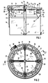
- the reaction vessel consists of a circular cylindrical container 1, for example made of sheet steel, which is surrounded by an edge reinforcement 34 (FIG. 2) on its upper edge.
- a sludge discharge nozzle 2 and a manhole 3 is indicated in his coat.
- the container 1 contains a reaction space 8; the means are also integrated into it, through which - as will be described later - the mixture treated in container 1 is separated into pure liquid, biomass and gaseous reaction products, especially methane and carbon dioxide.
- a central inlet and circulation pipe 4 is provided, which ends just above the bottom of the container 1 and is held in a foot-like frame 5, so that outlet openings 6 for the supplied or circulated liquid remain near the bottom, in which additionally a baffle-like, for. B. conical, chicane 7 is provided.
- the inlet pipe 4 contains at the level of the liquid level separating the reaction chamber 8 from an overlying gas chamber 10 closed off with a cover 9 against the environment, through openings 12 for the liquid to be circulated. These openings 12 partially protrude into the gas space 10 so that the reaction gases can be removed from the container 1 through the upper part of the tube 4 via a gas vent 13.
- a stirrer 15 driven by a motor 14 for conveying and circulating the liquid into and through the pipe 4 can be inserted into the gas-tight cover 52 of the inlet pipe 4 from above; furthermore, a feed line 16 opens into the pipe 4 for the raw liquid to be treated.
- an intermediate wall 17 is provided in the region of the liquid level 11, which in the first embodiment forms a ring concentric with the tube 4 and the container 1;
- an annular subspace 19 is separated from the reaction space 8.
- the annular partial space 19 is closed off by funnel-like sludge collecting pockets 21 formed by two inclined plates 22 and 23, from which a sludge passage slot 24 leads into the reaction space 8 as a sludge return opening.
- conveying and distribution devices 25 are distributed between the inclined clarifiers 20; their exact structure will be described later.
- the separated pure liquid is drawn off with the aid of collecting troughs 26 arranged on the inclined clarifiers 20, which open out into a circular trough 27 via small transverse troughs 29.
- the annular partial space 19 of the container 1 is open at the top and can be walked on via a peripheral lattice web 30, which is only indicated, which is connected at one point on the circumference to an access 31.
- a further web 32 which is also only sketched, leads radially into the center of the container 1.
- FIGS. 1 and 2 also show backflow lines 33 which lead from each conveyor device 25 to the central tube 4 at a slight downward angle and serve to return floating sludge separated in the conveyor device 25, as will be explained in connection with FIG. 7.
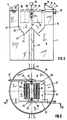
- two intermediate walls 17 running over the diameter of the container 1 cut a disk-like partial space 19 in the central region of the container 1 from the reaction chamber 8.
- this subspace 19 which in turn can be open and accessible at the top, which is not shown again explicitly, two oblique clarifiers 20 are arranged in the radial direction.
- a conveyor device 25 which contains a stirrer 35 designed as a wing propeller, which is driven by a motor 36.
- the conveying device 25 rests on a central column 37 which merges into a cylinder 38 which surrounds the stirrer 35 and which ends in an overflow edge 39.
- the interior of the cylinder 38 is in flow communication below the stirrer 35 through pipe socket 40 with the reaction chamber 8.
- the stirrer 35 sucks in treated mixture to be separated through these pipe sockets 40 and conveys it via the edge 39 into the subspace 19, from which - as the arrows indicate - it enters the inclined clarifier 20 from below for separating the biomass.
- the raw liquid to be treated is fed into the container 1 via two feed lines 41 schematically indicated in FIG. 4, which are preferably arranged in the vicinity of the container bottom.
- the intermediate wall 17 separates a cuboidal partial space 19 from the reaction space 8.
- two conveyors 35 are also provided in the conveying devices 25, which are connected to the reaction chamber 8 by pipe bends 42 passing through the wall 17 on the suction side.
- the mixture to be separated which is conveyed by the stirrers 35, is distributed to the inclined clarifier 20 via overflow edges 39.
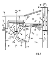
- the conveyor device 25 according to FIG. 1 contains one Wing propeller 35, which is driven by a motor 36.
- a pipe bend 43 leads through the intermediate wall 17 to a suction funnel 44 which is submerged below the level 11 in the liquid content of the reaction chamber 8 and is therefore filled with a mixture of liquid and biomass to be separated which has been treated in the reaction chamber 8.
- a funnel 45 connects to the stirrer 35, which in turn merges into a cylinder 38 with an overflow edge 39.
- the cylinder 38 is concentrically enclosed by a likewise funnel-shaped floating sludge separator 46, in the funnel of which openings 47 are provided for the passage of the conveyed mixture into the subspace 19 and thus into the inclined clarifier 20.
- the separator 46 serves on the one hand to calm the volume flow conveyed by the stirrer 35 and on the other hand to separate floating sludge, at the same time causing additional degassing of the mixture - into the free atmosphere in the example shown. Sludge separation and degassing are supported and promoted by a revolver 48 rotating with the stirrer 35.
- a radial channel 49 which opens into a sludge pot 50, from which the line 33 for the return transport of the sludge into the feed pipe 4 or the reaction space 8 runs out.
- the entire conveyor device 25 is mounted and held on or on two rail-like supports 51 (FIG. 2), which are designed in the radial direction between the container 1 and the intermediate wall 17.
Landscapes
- Life Sciences & Earth Sciences (AREA)
- Engineering & Computer Science (AREA)
- Health & Medical Sciences (AREA)
- Chemical & Material Sciences (AREA)
- Organic Chemistry (AREA)
- Bioinformatics & Cheminformatics (AREA)
- Wood Science & Technology (AREA)
- Zoology (AREA)
- Microbiology (AREA)
- Genetics & Genomics (AREA)
- Biotechnology (AREA)
- Sustainable Development (AREA)
- General Health & Medical Sciences (AREA)
- Biochemistry (AREA)
- Biomedical Technology (AREA)
- General Engineering & Computer Science (AREA)
- Molecular Biology (AREA)
- Hydrology & Water Resources (AREA)
- Oil, Petroleum & Natural Gas (AREA)
- Biodiversity & Conservation Biology (AREA)
- General Chemical & Material Sciences (AREA)
- Environmental & Geological Engineering (AREA)
- Water Supply & Treatment (AREA)
- Clinical Laboratory Science (AREA)
- Treatment Of Sludge (AREA)
- Apparatus Associated With Microorganisms And Enzymes (AREA)
- Processing Of Solid Wastes (AREA)
- Purification Treatments By Anaerobic Or Anaerobic And Aerobic Bacteria Or Animals (AREA)
- Steering Control In Accordance With Driving Conditions (AREA)
Priority Applications (1)
| Application Number | Priority Date | Filing Date | Title |
|---|---|---|---|
| AT85100494T ATE39680T1 (de) | 1984-11-20 | 1985-01-18 | Reaktionsgefaess. |
Applications Claiming Priority (2)
| Application Number | Priority Date | Filing Date | Title |
|---|---|---|---|
| CH5531/84 | 1984-11-20 | ||
| CH5531/84A CH662339A5 (de) | 1984-11-20 | 1984-11-20 | Reaktionsgefaess. |
Publications (3)
| Publication Number | Publication Date |
|---|---|
| EP0182955A1 EP0182955A1 (de) | 1986-06-04 |
| EP0182955B1 EP0182955B1 (de) | 1989-01-04 |
| EP0182955B2 true EP0182955B2 (de) | 1997-06-25 |
Family
ID=4295179
Family Applications (1)
| Application Number | Title | Priority Date | Filing Date |
|---|---|---|---|
| EP19850100494 Expired - Lifetime EP0182955B2 (de) | 1984-11-20 | 1985-01-18 | Reaktionsgefäss |
Country Status (8)
| Country | Link |
|---|---|
| US (1) | US4749480A (enExample) |
| EP (1) | EP0182955B2 (enExample) |
| JP (1) | JPS61129096A (enExample) |
| AT (1) | ATE39680T1 (enExample) |
| CA (1) | CA1257410A (enExample) |
| CH (1) | CH662339A5 (enExample) |
| DE (1) | DE3567196D1 (enExample) |
| IN (1) | IN163908B (enExample) |
Cited By (1)
| Publication number | Priority date | Publication date | Assignee | Title |
|---|---|---|---|---|
| DE102006015538A1 (de) * | 2006-03-31 | 2007-10-11 | H. C. Starck Gmbh & Co. Kg | Vorrichtung und Verfahren zur Herstellung von Verbindungen durch Fällung |
Families Citing this family (9)
| Publication number | Priority date | Publication date | Assignee | Title |
|---|---|---|---|---|
| US4883602A (en) * | 1988-08-22 | 1989-11-28 | Fluid Dynamics, Inc. | Decanting apparatus and method |
| DE4415017C2 (de) * | 1994-04-29 | 1996-02-15 | Bernstein Gmbh Ingenieurbuero | Zweistufiger Kombi-Biogasreaktor zur Aufbereitung pflanzlicher und tierischer Biomasse, insbesondere Gülle |
| NL1000100C2 (nl) * | 1995-04-10 | 1996-10-11 | Pacques Bv | Bezinkinrichting voor een vloeistof, gas, en deeltjesvormig materiaal bevatten fluïdum alsmede een hiervan voorziene reinigingsinrichting en werkwijze voor het reinigen van afvalwater. |
| AT407523B (de) * | 1996-12-20 | 2001-04-25 | En Service Gmbh | Biogasfermenteranlage |
| US5874003A (en) * | 1997-06-25 | 1999-02-23 | Rose; Bryan L. | Wastewater treatment apparatus with floating clarifier |
| CN2741976Y (zh) * | 2004-11-24 | 2005-11-23 | 深圳市普新科技有限公司 | 外水压式厌氧发酵装置 |
| DE102011008319B4 (de) * | 2011-01-11 | 2016-07-14 | Finsterwalder Umwelttechnik Gmbh & Co. Kg | Räumer für einen Fermenter zum Fördern von Räumgut, Fermenter und Verfahren zum Räumen von Räumgut |
| WO2013110821A1 (de) * | 2012-01-27 | 2013-08-01 | Voelkl Robert | Biogasanlage und komponenten hierfür |
| US11111168B1 (en) * | 2020-04-07 | 2021-09-07 | Ovivo Inc. | Tank with membrane cover and draft tube mixer |
Family Cites Families (9)
| Publication number | Priority date | Publication date | Assignee | Title |
|---|---|---|---|---|
| US2605220A (en) * | 1950-06-16 | 1952-07-29 | Dorr Co | Anaerobic digester |
| US3239067A (en) * | 1963-03-15 | 1966-03-08 | Lakeside Engineering Corp | Combined clarifier and digester of high capacity |
| GB1491502A (en) * | 1975-05-22 | 1977-11-09 | Biomech Ltd | Anaerobic digestion of water-polluting waste material |
| DE2554495B2 (de) * | 1975-12-04 | 1980-03-06 | Bayer Ag, 5090 Leverkusen | Vorrichtung zur biologischen Reinigung von Abwasser mit einem 10 bis 32 m hohen Begasungsbecken |
| EP0058247B1 (de) * | 1981-02-09 | 1985-10-23 | GebràDer Sulzer Aktiengesellschaft | Verfahren zur anaeroben Reinigung von mit organischen Stoffen belasteten Flüssigkeiten und Anlage zur Durchführung des Verfahrens |
| US4372856A (en) * | 1981-03-30 | 1983-02-08 | Morrison Jon R | Process and system for anaerobic treatment of waste |
| US4346005A (en) * | 1981-08-03 | 1982-08-24 | Crane Co. | Tube settler module |
| FR2537603B1 (fr) * | 1982-12-08 | 1985-07-12 | Guerin Maurice | Digesteur continu pour la production de biomethane a partir de substances organiques |
| US4530762A (en) * | 1984-03-28 | 1985-07-23 | Love Leonard S | Anaerobic reactor |
-
1984
- 1984-11-20 CH CH5531/84A patent/CH662339A5/de not_active IP Right Cessation
-
1985
- 1985-01-18 DE DE8585100494T patent/DE3567196D1/de not_active Expired
- 1985-01-18 EP EP19850100494 patent/EP0182955B2/de not_active Expired - Lifetime
- 1985-01-18 AT AT85100494T patent/ATE39680T1/de not_active IP Right Cessation
- 1985-09-23 IN IN772/DEL/85A patent/IN163908B/en unknown
- 1985-10-21 JP JP60235096A patent/JPS61129096A/ja active Pending
- 1985-11-12 US US06/797,425 patent/US4749480A/en not_active Expired - Fee Related
- 1985-11-19 CA CA000495644A patent/CA1257410A/en not_active Expired
Cited By (1)
| Publication number | Priority date | Publication date | Assignee | Title |
|---|---|---|---|---|
| DE102006015538A1 (de) * | 2006-03-31 | 2007-10-11 | H. C. Starck Gmbh & Co. Kg | Vorrichtung und Verfahren zur Herstellung von Verbindungen durch Fällung |
Also Published As
| Publication number | Publication date |
|---|---|
| US4749480A (en) | 1988-06-07 |
| EP0182955A1 (de) | 1986-06-04 |
| IN163908B (enExample) | 1988-12-03 |
| EP0182955B1 (de) | 1989-01-04 |
| DE3567196D1 (en) | 1989-02-09 |
| JPS61129096A (ja) | 1986-06-17 |
| CA1257410A (en) | 1989-07-11 |
| CH662339A5 (de) | 1987-09-30 |
| ATE39680T1 (de) | 1989-01-15 |
Similar Documents
| Publication | Publication Date | Title |
|---|---|---|
| DE2216767C3 (de) | Vorrichtung zur biologischen Reinigung von Abwasser | |
| EP0567601B1 (de) | Verfahren und vorrichtung zur klärung von abwasser | |
| DE1459464A1 (de) | Verfahren und Vorrichtung zur Faulschlammbehandlung | |
| CH616906A5 (enExample) | ||
| EP0182955B2 (de) | Reaktionsgefäss | |
| DE69735165T2 (de) | Dreizonenvorrichtung zur reinigung durch flotation mit gelöster luft mit verbessertem wirkungsgrad | |
| EP0338198B1 (de) | Absetzbehälter für eine Belebtschlamm-Abwasser-Suspension | |
| DE2251341A1 (de) | Speisebehaelter | |
| DE2456953C3 (de) | Vorrichtung zum biologischen Aufbereiten von Abwässern | |
| DE1657280B2 (de) | Separator | |
| DE2743956A1 (de) | Vorrichtung zur gleichzeitigen behandlung von primaeren und sekundaeren abwasserschlaemmen | |
| JPH07507958A (ja) | 廃水処理装置 | |
| US2798042A (en) | System of sewage treatment and process | |
| DE2806109C2 (de) | Vorrichtung zum Reinigen von Flüssigkeiten | |
| EP0564935A1 (de) | Kläreinrichtung für Abwässer | |
| DE2403334A1 (de) | Klaeranlage | |
| DE2125025B2 (de) | Vorrichtung zur Behandlung von Abwasser | |
| DE3244090A1 (de) | Geraet zum foerdern von fluessigkeiten und zum abscheiden von in den fluessigkeiten enthaltenen gasen | |
| DE2219729B2 (de) | Transportable Kläranlage für Abwasser | |
| DE3150987A1 (de) | "vorrichtung zum schwebbarmachen von in einer fluessigkeit suspendierten teilchen mittels gasblasen" | |
| DE2317356C3 (de) | Kläranlage zum Behandeln von Abwasser | |
| AT391854B (de) | Vorrichtung zur aeroben abwasserreinigung | |
| CH640424A5 (en) | Process and device for continuous separation of foam | |
| EP0117463A2 (de) | Verfahren und Einrichtung zur Be- und Entgasung von Flüssigkeiten | |
| DE1658081C3 (de) | Vorrichtung zum Umwälzen und Belüften von Abwasser in einem Belebungsbecken mit einem um eine vertikale Achse drehbaren Belüftungskreisel |
Legal Events
| Date | Code | Title | Description |
|---|---|---|---|
| PUAI | Public reference made under article 153(3) epc to a published international application that has entered the european phase |
Free format text: ORIGINAL CODE: 0009012 |
|
| AK | Designated contracting states |
Kind code of ref document: A1 Designated state(s): AT BE DE FR GB IT LU NL SE |
|
| 17P | Request for examination filed |
Effective date: 19860901 |
|
| 17Q | First examination report despatched |
Effective date: 19880311 |
|
| GRAA | (expected) grant |
Free format text: ORIGINAL CODE: 0009210 |
|
| AK | Designated contracting states |
Kind code of ref document: B1 Designated state(s): AT BE DE FR GB IT LU NL SE |
|
| REF | Corresponds to: |
Ref document number: 39680 Country of ref document: AT Date of ref document: 19890115 Kind code of ref document: T |
|
| ITF | It: translation for a ep patent filed | ||
| GBT | Gb: translation of ep patent filed (gb section 77(6)(a)/1977) | ||
| REF | Corresponds to: |
Ref document number: 3567196 Country of ref document: DE Date of ref document: 19890209 |
|
| ET | Fr: translation filed | ||
| PLBI | Opposition filed |
Free format text: ORIGINAL CODE: 0009260 |
|
| 26 | Opposition filed |
Opponent name: HARRENDORF, HEINZ Effective date: 19891002 |
|
| NLR1 | Nl: opposition has been filed with the epo |
Opponent name: HARRENDORF, HEINZ |
|
| PGFP | Annual fee paid to national office [announced via postgrant information from national office to epo] |
Ref country code: FR Payment date: 19921212 Year of fee payment: 9 |
|
| PGFP | Annual fee paid to national office [announced via postgrant information from national office to epo] |
Ref country code: LU Payment date: 19921217 Year of fee payment: 9 |
|
| PGFP | Annual fee paid to national office [announced via postgrant information from national office to epo] |
Ref country code: BE Payment date: 19921222 Year of fee payment: 9 |
|
| PGFP | Annual fee paid to national office [announced via postgrant information from national office to epo] |
Ref country code: SE Payment date: 19921228 Year of fee payment: 9 |
|
| ITTA | It: last paid annual fee | ||
| PGFP | Annual fee paid to national office [announced via postgrant information from national office to epo] |
Ref country code: NL Payment date: 19930131 Year of fee payment: 9 |
|
| EPTA | Lu: last paid annual fee | ||
| PG25 | Lapsed in a contracting state [announced via postgrant information from national office to epo] |
Ref country code: LU Free format text: LAPSE BECAUSE OF NON-PAYMENT OF DUE FEES Effective date: 19940118 |
|
| PG25 | Lapsed in a contracting state [announced via postgrant information from national office to epo] |
Ref country code: SE Effective date: 19940119 |
|
| PG25 | Lapsed in a contracting state [announced via postgrant information from national office to epo] |
Ref country code: BE Effective date: 19940131 |
|
| BERE | Be: lapsed |
Owner name: GEBRUDER SULZER A.G. Effective date: 19940131 |
|
| PG25 | Lapsed in a contracting state [announced via postgrant information from national office to epo] |
Ref country code: NL Effective date: 19940801 |
|
| NLV4 | Nl: lapsed or anulled due to non-payment of the annual fee | ||
| PG25 | Lapsed in a contracting state [announced via postgrant information from national office to epo] |
Ref country code: FR Effective date: 19940930 |
|
| REG | Reference to a national code |
Ref country code: FR Ref legal event code: ST |
|
| EUG | Se: european patent has lapsed |
Ref document number: 85100494.5 Effective date: 19940810 |
|
| PLAW | Interlocutory decision in opposition |
Free format text: ORIGINAL CODE: EPIDOS IDOP |
|
| PLAW | Interlocutory decision in opposition |
Free format text: ORIGINAL CODE: EPIDOS IDOP |
|
| PUAH | Patent maintained in amended form |
Free format text: ORIGINAL CODE: 0009272 |
|
| STAA | Information on the status of an ep patent application or granted ep patent |
Free format text: STATUS: PATENT MAINTAINED AS AMENDED |
|
| 27A | Patent maintained in amended form |
Effective date: 19970625 |
|
| AK | Designated contracting states |
Kind code of ref document: B2 Designated state(s): AT BE DE FR GB IT LU NL SE |
|
| GBTA | Gb: translation of amended ep patent filed (gb section 77(6)(b)/1977) | ||
| ITF | It: translation for a ep patent filed | ||
| EN | Fr: translation not filed | ||
| PGFP | Annual fee paid to national office [announced via postgrant information from national office to epo] |
Ref country code: GB Payment date: 20011214 Year of fee payment: 18 |
|
| REG | Reference to a national code |
Ref country code: GB Ref legal event code: IF02 |
|
| PG25 | Lapsed in a contracting state [announced via postgrant information from national office to epo] |
Ref country code: GB Free format text: LAPSE BECAUSE OF NON-PAYMENT OF DUE FEES Effective date: 20030118 |
|
| GBPC | Gb: european patent ceased through non-payment of renewal fee | ||
| PGFP | Annual fee paid to national office [announced via postgrant information from national office to epo] |
Ref country code: AT Payment date: 20040102 Year of fee payment: 20 |
|
| PGFP | Annual fee paid to national office [announced via postgrant information from national office to epo] |
Ref country code: DE Payment date: 20040108 Year of fee payment: 20 |
|
| APAH | Appeal reference modified |
Free format text: ORIGINAL CODE: EPIDOSCREFNO |