EP0182089A1 - Flat wringing apparatus for mops - Google Patents
Flat wringing apparatus for mops Download PDFInfo
- Publication number
- EP0182089A1 EP0182089A1 EP85113033A EP85113033A EP0182089A1 EP 0182089 A1 EP0182089 A1 EP 0182089A1 EP 85113033 A EP85113033 A EP 85113033A EP 85113033 A EP85113033 A EP 85113033A EP 0182089 A1 EP0182089 A1 EP 0182089A1
- Authority
- EP
- European Patent Office
- Prior art keywords
- mop
- housing
- jaw sections
- press
- carriers
- Prior art date
- Legal status (The legal status is an assumption and is not a legal conclusion. Google has not performed a legal analysis and makes no representation as to the accuracy of the status listed.)
- Granted
Links
Images


Classifications
-
- A—HUMAN NECESSITIES
- A47—FURNITURE; DOMESTIC ARTICLES OR APPLIANCES; COFFEE MILLS; SPICE MILLS; SUCTION CLEANERS IN GENERAL
- A47L—DOMESTIC WASHING OR CLEANING; SUCTION CLEANERS IN GENERAL
- A47L13/00—Implements for cleaning floors, carpets, furniture, walls, or wall coverings
- A47L13/10—Scrubbing; Scouring; Cleaning; Polishing
- A47L13/50—Auxiliary implements
- A47L13/58—Wringers for scouring pads, mops, or the like, combined with buckets
- A47L13/59—Wringers for scouring pads, mops, or the like, combined with buckets with movable squeezing members
Definitions
- a mop flat press designated as a whole by 1, is hereinafter referred to as "press 1" for short. It has a press housing 2 with a laterally closed housing frame 3, which is approximately rectangular in plan (FIG. 3) and open at the top. The two side cheeks 4 a and 4 b of the housing 2 protrude from the rear of the housing 6 to the rear. The lower part of a cleaning mop 8 can be inserted into the upper opening 7 of the housing 2, as indicated by dash-dotted lines in FIG. 1. Such, used for cleaning floors, etc. mops are known to have numerous cord-like fringes 8 a, some of which are indicated by dashed lines in Fig. 1.
- each rack 15 engages a toothed segment 14 which is secured against rotation on a common adjusting shaft 12.
- the actuating lever 11 is secured against rotation on this adjusting shaft 12.
- the operating lever 11 is drawn for better clarity, deviating from its actual starting position, pivoted about 60 ° to the right. Its actual position is indicated by dash-dotted lines in FIG. 2 by the line '11.
- the actuating lever 11 is pressed down according to the arrow 32 (FIG. 2). As a result, the jaw sections 18 are moved in the direction of the end face of the housing 2 in accordance with the double arrows 30 in FIG.
- the pressure jaw sections 18 are also called “jaw sections 18" for short here.
- the side cheek 4 b is designed analogously to the side cheek 4 a described in more detail in FIG. 2 and contains corresponding parts of the adjustment mechanism '13. 1 that the pressure surfaces 40 of the jaw sections 18 facing the mop 8 are profiled. They each have a longitudinal rib 39 at the level of the associated guide slot 19. This not only stabilizes the individual jaw sections 18 a, 18 b etc., but also promotes the pressing out of the mop fringes 8 a.
Abstract
Description
Die Erfindung betrifft eine Mop-Flachpresse gemäß dem Oberbegriff des ersten Anspruches.The invention relates to a mop flat press according to the preamble of the first claim.
Bisher bekannte Mop-Flachpressen dieser Art sind zwar verhältnismäßig einfach in ihrem Aufbau, haben jedoch noch etliche Nachteile. So kennt man bereits seit langer Zeit Mop-Flachpressen mit einem etwa U-förmigen Gehäuseteil, an dessen offener Seite ein flaches, in Richtung auf den U-Steg des Gehäuses hin verstellbares Pressteil vorgeshehen ist. Dieses läßt sich über einen Verstellhebel und einen zugehörigen Hebelmechanismus in Richtung auf den Mop drücken, wenn sich dieser im Gehäuse befindet. Das verstellbare Pressteil ist flach und einstückig durchgehend ausgebildet, so daß es gewissermaßen die vierte Wand des Gehäuses bildet. Nachteilig an dieser Ausführungsform ist insbesondere, daß es nicht zu einer genügend guten Auspressung des Mops kommt, wenn in den Mop-Fransen Knoten oder andere Verdickungen vorhanden sind. Diese bestimmen dann praktisch die innere Endstellung des Pressteils und die übrigen Mop-Bereiche werden nicht oder nicht genügend unter Druck gesetzt, so daß das im Mop befindliche Wasser od. dgl. Flüssigkeit nicht genügend gut entfernt werden kann. Dabei ist auch zu beachten, daß der Mop bei der praktischen Handhabung nicht leicht einigermaßen gleichmäßig innerhalb des Pressraumes der Mop-Flachpresse unterzubringen ist oder ein solches gleichmäßiges Unterbringen zumindest wesentlich mehr Arbeitsaufwand macht. Eine Bedienungsperson, also gewöhnlich eine Frau, die putzt, befaßt sich auch bei ihrem üblichen Arbeitsablauf nicht damit, den auszupressenden Mop besonders gleichmäßig und vorteilhaft für den Auspressvorgang innerhalb der Mop-Flachpresse unterzubringen. Außerdem ist der i. d. Regel aus Hebeln bestehende Übertragungsmechanismus vom Betätigungshebel zum Pressteil bei den bisher bekannten Mop-Flachpressen verhältnismäßig ungünstig, so daß das Auspressen des Mops verhältnismäßig viel Kraftaufwand erfordert.So far known mop flat presses of this type are relatively simple in their construction, but still have a number of disadvantages. For example, flat mop presses have been known for a long time with an approximately U-shaped housing part, on the open side of which there is a flat pressed part which is adjustable in the direction of the U-web of the housing. This can be pressed in the direction of the mop via an adjusting lever and an associated lever mechanism when it is in the housing. The adjustable press part is flat and integrally formed so that it forms the fourth wall of the housing. A particular disadvantage of this embodiment is that the mop is not squeezed out sufficiently well if knots or other thickenings are present in the mop fringes. These then practically determine the inner end position of the pressed part and the remaining mop areas are not or not sufficiently pressurized, so that the water or the like liquid in the mop cannot be removed sufficiently well. It should also be noted that the practical handling of the mop is not easy to accommodate reasonably evenly within the pressing space of the flat mop press, or that such a uniform placement at least requires considerably more work. An operator, usually a woman who is cleaning, is not concerned with accommodating the mop to be pressed out evenly and advantageously for the pressing out process within the flat mop press, even in her usual workflow. In addition, the id usually transmission mechanism consisting of levers from the operating lever to the pressing part in the previously known flat mop presses is relatively unfavorable, so that pressing out the mop requires a relatively large amount of force.
Es besteht daher die Aufgabe, eine Mop-Flachpresse der eingangs erwähnten Art zu verbessern. Insbesondere soll dabei ein gleichmäßiges und gutes Auspressen des Mops erreicht werden. Weiterhin ist eine gute Bedienbarkeit der Mop-Flachpresse erwünscht.There is therefore the task of improving a flat mop press of the type mentioned at the beginning. In particular, a uniform and good pressing out of the pug should be achieved. Good operability of the flat mop press is also desirable.
Die erfindungsgemäße Lösung dieser Aufgabe besteht insbesondere darin, daß eine Mop-Presse der eingangs erwähnten Art eine verstellbare Halterung für mindestens zwei separate, das Pressteil bildende Druckbackenabschnitte hat, von denen wenigstens ein Backenabschnitt um seine Lagerstelle in der Halterung verschwenkbar angeordnet ist.The solution to this problem according to the invention consists in particular in that a mop press of the type mentioned at the outset has an adjustable holder for at least two separate pressure jaw sections forming the pressed part, of which at least one jaw section is arranged pivotably about its bearing point in the holder.
Derartige, voneinander unabhängig gelagerte Druckbackenabschnitte können sich wesentlich besser an den auszupressenden Mop anpassen, insbesondere auch dann, wenn dieser Knoten, Verdickungen od. dgl. aufweist.Such pressure jaw sections, which are mounted independently of one another, can adapt much better to the mop to be pressed out, in particular also if this has knots, thickenings or the like.
Weiterbildungen der Neuerung sind in weiteren Unteransprüchen aufgeführt. Nachstehend wird die Erfindung anhand eines vorteilhaften Ausführungsbeispieles in Verbindung mit der Zeichnung noch näher erläutert. Es zeigen
- Fig.1 eine teilweise im Schnitt gehaltene Seitenansicht der Mop-Flachpresse,
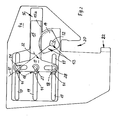
- Fig.2 eine Seitenansicht der Mop-Flachpresse bei abgenommenem Getriebedeckel und
- Fig.3 eine Aufsicht auf die Mop-Flachpresse.
- 1 is a partially sectioned side view of the flat mop press,
- 2 shows a side view of the flat mop press with the gear cover removed and
- 3 shows a top view of the flat mop press.
Eine im ganzen mit 1 bezeichnete Mop-Flachpresse wird nachstehend kurz "Presse 1" genannt. Sie hat ein Pressen-Gehäuse 2 mit einem seitlich geschlossenen Gehäuserahmen 3, der im Grundriß (Fig. 3) etwa rechteckig und oben offen ist. Die beiden Seitenwangen 4 a und 4 b des Gehäuses 2 stehen über die Gehäuse-Rückseite 6 nach hinten vor. In die obere Öffnung 7 des Gehäuses 2 kann, wie in Fig. 1 im Ausschnitt strichpunktiert angedeutet, der untere Teil eines Reinigungsmops 8 eingesteckt werden. Derartige, zum Reinigen von Fußböden usw. dienende Mops haben bekanntermaßen zahlreiche schnurartige Fransen 8 a, von denen in Fig. 1 einige strichliniert angedeutet sind. Wenn derartige Mops 8 Feuchtigkeit aufnehmen, sei es zum Spülen und Reinigen ihrer Fransen 8 a, sei es beim Aufwischen von Flüssigkeit vom Boden, sollen sie mit der Presse 1 auf einfache Weise schnell ausgedrückt werden können. Das untere Ende des Mops 8 mit seinen Fransen 8 a wird dann, wie in Fig. 1 teilweise angedeutet, in das Gehäuse 2 eingeführt, und ein noch näher erläutertes Pressteil wird mit Hilfe eines Betätigungshebels 11 in Richtung der Stirnseite 5 des Gehäuses 2 verschoben, so daß die feuchten, schnurartigen Fransen 8 a gegen die Stirnseite 5 gedrückt und ausgepresst werden. Die ausgepresste Flüssigkeit, für gewöhnlich Putzwasser, kann durch die im Gehäuseboden 9 befindlichen Ablauflöcher 10 in Richtung der Pfeile 21 nach unten abfließen. In Fig. 1 und 2 erkennt man auch noch gut einen Aufsatz-Schlitz 20 sowie an dessen unterem Ende einen Anschlag 22. Mit Hilfe dieser in den Seitenwangen 4 befindlichen Aufsatz-Schlitzen 20 bzw. Anschlägen 22 kann die gesamte Presse 1 in bekannter Weise gut auf den in Fig. 1 strichpunktiert angedeuteten Oberrand 23 eines Behälters aufgesetzt werden, in dem die von der Presse 1 ausgedrückte Flüssigkeit hineinlaufen kann.A mop flat press, designated as a whole by 1, is hereinafter referred to as "
Bei der erfindungsgemäßen Presse 1 ist nun, wie besonders gut aus Fig. 1 und 2 erkennbar, eine verstellbare Halterung 17 für mindestens zwei ein Pressteil bildende Druckbackenabschnitte 18 a und 18 b bzw. 18 c vorgesehen, von denen wenigstens ein Backenabschnitt, z. B. 18 a, um seine Lagerstelle 26, 27 oder 28 in der Halterung 17 etwas verschwenkbar angeordnet ist, wie die Doppelpfeile 29 in Fig. 1 andeuten. Die dort ebenfalls angedeuteten Doppelpfeile 30 sind in Richtung von Führungsschlitzen 19 orientiert, in denen die Backenabschnitte 18 a bis 18 c sich führen, wenn sie die Press- bzw. die öffnungsbewegung durchführen. Im Ausführungsbeispiel ist die Presse 1 mit drei Backenabschnitten 18 a, 18 b, 18 c versehen, was sich in der Praxis als vorteilhaft zum Auspressen des Mops 8 erwiesen hat. Einzelne Verdickungen, Knoten od. dgl. in den Mop-Fransen 8 a können bei einer solchen Anordnung nicht dazu führen, daß weite Bereiche der Mop-Fransen 8 a nicht ausreichend angepresst werden. Vielmehr können sich die einzelnen Backenabschnitte gut entsprechenden Abschnitten des Mops 8 anpassen. Dies wird auch noch dadurch begünstigt, daß mindestens zwei, vorzugsweise alle Backenabschnitte 18 etwas verschwenkbar auf der Halterung 17 angeordnet sind. Die in Fig. 1 gut erkennbare Ausgangslage der Backenabschnitte 18, bei der die Backenrücken 30 etwa lotrecht oder ungefähr._ parallel zur Stirnseite 5 gehalten sind, wird dadurch aufrechterhalten, daß sich die Backenabschnitte 18 in den Führungsschlitzen 19 der Seitenwangen 4 führen, und zwar mit Hilfe von Führungsbolzen 41. Die durch die Doppelpfeile 30 angedeutete Verschiebebewegung der Backenabschnitte 18 während des Auspressens des Mops 8 und seiner Freigabe ist auf bequeme Weise durch einen im ganzen mit 13 bezeichneten Verstellmechanismus zu bewirken. Fig. 2 zeigt dabei eine Seitenwange 4 a des Gehäuses 2, und zwar bei abgenommenem Seitendeckel 31. Man erkennt, daß der Verstellmechanismus in jeder Seitenwange 4 eine dort geführte Halterung 17 aufweist, die eine Zahnstange 15 hat, welche sich in einer nutenartigen Stangenführung 16 führt. In die Zahnung 15 a jeder Zahnstange 15 greift ein Zahnsegment 14 an, das auf einer gemeinsamen Verstellwelle 12 verdrehsicher befestigt ist. An der Außenseite der einen Seitenwange 4 a ist der Betätigungshebel 11 drehgesichert auf dieser Verstellwelle 12 befestigt. In Fig. 1 ist der Betätigungshebel 11 der besseren Übersicht wegen, abweichend von seiner tatsächlichen Ausgangsstellung, etwa um 60° nach rechts verschwenkt gezeichnet. Seine tatsächliche Lage ist in Fig. 2 strichpunktiert durch die Linie '11 angedeutet. Zum Verstellen der Backenabschnitte 18 wird der Betätigungshebel 11 entsprechend dem Pfeil 32 (Fig.2) nach unten gedrückt. Dadurch werden mit Hilfe des vorbeschriebenen Mechanismus '13 die Backenabschnitte 18 entsprechend den Doppelpfeilen 30 in Fig. 1 in Richtung der Stirnseite des Gehäuses 2 bewegt. Der Druck auf die Fransen 8 a wird in erwünschter Weise seitlich ausgeübt und die Flüssigkeit kann nach unten ablaufen. Mit dem vorbeschriebenen Verstellmechanismus 13 kann - bei sonst gleichen Verhältnissen - eine verhältnismäßig große Auspresskraft auf den Mop 8 übertragen werden, woraus sich eine gute Auspressung beim Mop 8 ergibt.In the
Die Druckbackenabschnitte 18 werden hier auch verkürzt "Backenabschnitte 18" genannt. Die Seitenwange 4 b ist analog wie die in Fig. 2 näher beschriebene Seitenwange 4 a ausgebildet und enthält entsprechende Teile des Verstellmechanismus '13. In Fig. 1 erkennt man gut, daß die dem Mop 8 zugewandten Druckflächen 40 der Backenabschnitte 18 profiliert ausgebildet sind. Sie weisen jeweils in Höhe des zugehörigen Führungsschlitzes 19 eine Längsrippe 39 auf. Dadurch werden nicht nur die einzelnen Backenabschnitte 18 a, 18 b usw. stabilisiert, sondern es wird auch das Auspressen der Mopfransen 8 a begünstigt.The
In Fig. 2 erkennt man gut, daß an den (dort gestrichelt angedeuteten) Backenabschnitten 18 Führungsbolzen 41 vorgesehen sind, welche die Führungsschlitze 19 mit Spiel durchsetzen. Auf diese Weise sind die einzelnen Backenabschnitte einerseits derart gefügt, daß ihre Druckfläche 40 etwa parallel zur Längsrichtung der Mop- fransen 8 a gehalten sind. Andererseits erlaubt das in Fig. 2 gut sichtbare Spiel zwischen dem Führungsbolzen 41 und den benachbarten Wänden des Führungsschlitzes 19, daß sich jeder Backenabschnitt 18 etwas um seine zugehörige Lagerstelle 26, 27 oder 28 verschwenken kann.In Fig. 2 it can be clearly seen that 18
uer Radius der Zahnsegmente 14 od. dgl. einerseits und die Zahnstangen 15 sind vorzugsweise so ausgebildet, daß sich ein Untersetzungsverhältnis in dem Sinne ergibt, daß eine Verschwenkbewegung des Betätigungshebels 11 zu einer besonders kräfigen Andruckbewegung bei den Druckbackenabschnitten 18 führt.The radius of the
Alle vorbeschriebenen oder in den Ansprüchen aufgeführten Einzelmerkmale können einzeln oder in beliebiger Kombination miteinander erfindungswesentlich sein.All of the individual features described above or listed in the claims can be essential to the invention individually or in any combination with one another.
Claims (7)
Priority Applications (1)
| Application Number | Priority Date | Filing Date | Title |
|---|---|---|---|
| AT85113033T ATE43484T1 (en) | 1984-11-17 | 1985-10-15 | ''MOP FLAT PRESS''. |
Applications Claiming Priority (2)
| Application Number | Priority Date | Filing Date | Title |
|---|---|---|---|
| DE19848433865U DE8433865U1 (en) | 1984-11-17 | 1984-11-17 | MOP FLAT PRESS |
| DE8433865U | 1984-11-17 |
Publications (2)
| Publication Number | Publication Date |
|---|---|
| EP0182089A1 true EP0182089A1 (en) | 1986-05-28 |
| EP0182089B1 EP0182089B1 (en) | 1989-05-31 |
Family
ID=6772839
Family Applications (1)
| Application Number | Title | Priority Date | Filing Date |
|---|---|---|---|
| EP85113033A Expired EP0182089B1 (en) | 1984-11-17 | 1985-10-15 | Flat wringing apparatus for mops |
Country Status (5)
| Country | Link |
|---|---|
| US (1) | US4663798A (en) |
| EP (1) | EP0182089B1 (en) |
| AT (1) | ATE43484T1 (en) |
| DE (2) | DE8433865U1 (en) |
| ES (1) | ES296292Y (en) |
Cited By (4)
| Publication number | Priority date | Publication date | Assignee | Title |
|---|---|---|---|---|
| EP0824008A2 (en) * | 1996-08-12 | 1998-02-18 | A.Z. International S.A. | Wringer for mops or scouring cloths |
| CN108577724A (en) * | 2018-07-02 | 2018-09-28 | 遂宁市长丰机械科技有限公司 | Drag pa pull-out type automatic cleaning vehicle |
| CN108852213A (en) * | 2018-07-02 | 2018-11-23 | 邹家福 | Base formula drags pa automatic rinser |
| CN111973105A (en) * | 2020-09-02 | 2020-11-24 | 马壮壮 | Mop bucket kit externally connected with faucet |
Families Citing this family (9)
| Publication number | Priority date | Publication date | Assignee | Title |
|---|---|---|---|---|
| US4707877A (en) * | 1986-06-26 | 1987-11-24 | Tu-Way Products Company | Wet mop liquid extractor |
| GB9003175D0 (en) * | 1990-02-13 | 1990-04-11 | Brute Ltd | Mop wringers and buckets |
| DE4011713A1 (en) * | 1990-04-11 | 1991-10-17 | Ewu Ag | CLEANER |
| GB2276077B (en) * | 1993-03-17 | 1996-07-17 | Scot Young Research | Improvements in or relating to mop wringers |
| DE4320454A1 (en) * | 1993-06-21 | 1994-12-22 | Henkel Ecolab Gmbh & Co Ohg | Mobile cleaning trolley |
| US5926896A (en) * | 1997-11-25 | 1999-07-27 | Rubbermaid Commercial Products Llc | Collapsible cleaning implement |
| USD427738S (en) * | 1999-04-09 | 2000-07-04 | Rubbermaid Commercial Products Llc | Mop wringer |
| US20050252921A1 (en) * | 2004-05-05 | 2005-11-17 | Rubbermaid Commercial Products Llc | Disinfecting bucket |
| US8627541B2 (en) * | 2005-10-19 | 2014-01-14 | Unger Marketing International, Llc | Mop press having top and bottom cam tracks |
Citations (3)
| Publication number | Priority date | Publication date | Assignee | Title |
|---|---|---|---|---|
| US1659505A (en) * | 1927-02-15 | 1928-02-14 | Welch William Henry | Mop wringer |
| DE1912589A1 (en) * | 1968-03-29 | 1969-10-16 | Eastman Kodak Co | Electrophotographic recording material |
| GB2011249A (en) * | 1977-12-30 | 1979-07-11 | Fesher H | Apparatus for metering the moisture of moist cleaning equipment for cleaning buildings |
Family Cites Families (4)
| Publication number | Priority date | Publication date | Assignee | Title |
|---|---|---|---|---|
| US1128083A (en) * | 1914-05-02 | 1915-02-09 | William Henry Welch | Mop-wringer. |
| US2802233A (en) * | 1954-10-28 | 1957-08-13 | Eberly Ernest Edward | Mop wringer |
| GB1090194A (en) * | 1966-04-23 | 1967-11-08 | Geerpres Europ Ltd | Improvements relating to mop wringers |
| US3452379A (en) * | 1966-06-09 | 1969-07-01 | Beatrice Foods Co | Cleaning apparatus |
-
1984
- 1984-11-17 DE DE19848433865U patent/DE8433865U1/en not_active Expired
-
1985
- 1985-10-15 EP EP85113033A patent/EP0182089B1/en not_active Expired
- 1985-10-15 AT AT85113033T patent/ATE43484T1/en active
- 1985-10-15 DE DE8585113033T patent/DE3570586D1/en not_active Expired
- 1985-11-15 US US06/798,482 patent/US4663798A/en not_active Expired - Fee Related
- 1985-11-15 ES ES1985296292U patent/ES296292Y/en not_active Expired
Patent Citations (3)
| Publication number | Priority date | Publication date | Assignee | Title |
|---|---|---|---|---|
| US1659505A (en) * | 1927-02-15 | 1928-02-14 | Welch William Henry | Mop wringer |
| DE1912589A1 (en) * | 1968-03-29 | 1969-10-16 | Eastman Kodak Co | Electrophotographic recording material |
| GB2011249A (en) * | 1977-12-30 | 1979-07-11 | Fesher H | Apparatus for metering the moisture of moist cleaning equipment for cleaning buildings |
Cited By (5)
| Publication number | Priority date | Publication date | Assignee | Title |
|---|---|---|---|---|
| EP0824008A2 (en) * | 1996-08-12 | 1998-02-18 | A.Z. International S.A. | Wringer for mops or scouring cloths |
| EP0824008A3 (en) * | 1996-08-12 | 1999-09-22 | A.Z. International S.A. | Wringer for mops or scouring cloths |
| CN108577724A (en) * | 2018-07-02 | 2018-09-28 | 遂宁市长丰机械科技有限公司 | Drag pa pull-out type automatic cleaning vehicle |
| CN108852213A (en) * | 2018-07-02 | 2018-11-23 | 邹家福 | Base formula drags pa automatic rinser |
| CN111973105A (en) * | 2020-09-02 | 2020-11-24 | 马壮壮 | Mop bucket kit externally connected with faucet |
Also Published As
| Publication number | Publication date |
|---|---|
| ES296292U (en) | 1987-08-01 |
| ES296292Y (en) | 1988-02-16 |
| ATE43484T1 (en) | 1989-06-15 |
| DE8433865U1 (en) | 1985-02-14 |
| DE3570586D1 (en) | 1989-07-06 |
| EP0182089B1 (en) | 1989-05-31 |
| US4663798A (en) | 1987-05-12 |
Similar Documents
| Publication | Publication Date | Title |
|---|---|---|
| DE4110830C1 (en) | ||
| DE3000217C2 (en) | Device for transferring cut wires from a loose wire bundle into a single layer of parallel wires | |
| DE3935659C2 (en) | ||
| EP0182089A1 (en) | Flat wringing apparatus for mops | |
| EP0256245B1 (en) | Tool holder for a folding machine or the like | |
| EP2872022B1 (en) | Frame for mop covers | |
| CH639706A5 (en) | DEVICE FOR COUPLING AN EXTENSION WITH A WEBSHAFT FRAME. | |
| EP2218388B1 (en) | Apparatus for wringing cleaning implements | |
| DE1293983B (en) | Cleaning device with cleaning tool attached to a holder | |
| DE2928950C2 (en) | Device for removing fermentation fodder from mobile silos | |
| DE854077C (en) | Device for cleaning floors, walls, ceilings, etc. | |
| DE1291098B (en) | Device for applying edge strips made of veneer or plastic | |
| DE2149882A1 (en) | Stripping tool | |
| DE3534664C2 (en) | ||
| DE3807010C2 (en) | Shower partition with swing-out door elements | |
| DE4444506C1 (en) | Device for cutting material into slices, strips or cubes | |
| DE2308683B2 (en) | Recording and / or reproducing device | |
| DE10201797A1 (en) | Ball press has a wire surrounding the unit and a press housing with a pressing area and movable press stamp | |
| DE483302C (en) | Seed dressing device with drum and mixing bars | |
| DE102004061893A1 (en) | Wet mop with a flat holder | |
| AT217928B (en) | Device for arranging inner and outer boxes, in particular match boxes | |
| DE3237936C2 (en) | ||
| DE3700253A1 (en) | BANDSAW FOR DIVIDING ANIMAL BODIES | |
| DE948323C (en) | Machine for making brushes | |
| DE1461545C (en) | Drawing device for producing diagrammatic drawings |
Legal Events
| Date | Code | Title | Description |
|---|---|---|---|
| PUAI | Public reference made under article 153(3) epc to a published international application that has entered the european phase |
Free format text: ORIGINAL CODE: 0009012 |
|
| AK | Designated contracting states |
Kind code of ref document: A1 Designated state(s): AT CH DE FR GB IT LI NL SE |
|
| 17P | Request for examination filed |
Effective date: 19860527 |
|
| RAP1 | Party data changed (applicant data changed or rights of an application transferred) |
Owner name: INTERPAT LTD. |
|
| 17Q | First examination report despatched |
Effective date: 19870806 |
|
| GRAA | (expected) grant |
Free format text: ORIGINAL CODE: 0009210 |
|
| AK | Designated contracting states |
Kind code of ref document: B1 Designated state(s): AT CH DE FR GB IT LI NL SE |
|
| PG25 | Lapsed in a contracting state [announced via postgrant information from national office to epo] |
Ref country code: IT Free format text: LAPSE BECAUSE OF FAILURE TO SUBMIT A TRANSLATION OF THE DESCRIPTION OR TO PAY THE FEE WITHIN THE PRESCRIBED TIME-LIMIT;WARNING: LAPSES OF ITALIAN PATENTS WITH EFFECTIVE DATE BEFORE 2007 MAY HAVE OCCURRED AT ANY TIME BEFORE 2007. THE CORRECT EFFECTIVE DATE MAY BE DIFFERENT FROM THE ONE RECORDED. Effective date: 19890531 Ref country code: GB Effective date: 19890531 Ref country code: NL Effective date: 19890531 Ref country code: SE Effective date: 19890531 |
|
| REF | Corresponds to: |
Ref document number: 43484 Country of ref document: AT Date of ref document: 19890615 Kind code of ref document: T |
|
| REF | Corresponds to: |
Ref document number: 3570586 Country of ref document: DE Date of ref document: 19890706 |
|
| PG25 | Lapsed in a contracting state [announced via postgrant information from national office to epo] |
Ref country code: AT Effective date: 19891015 |
|
| EN | Fr: translation not filed | ||
| PG25 | Lapsed in a contracting state [announced via postgrant information from national office to epo] |
Ref country code: LI Effective date: 19891031 Ref country code: CH Effective date: 19891031 |
|
| NLV1 | Nl: lapsed or annulled due to failure to fulfill the requirements of art. 29p and 29m of the patents act | ||
| PLBE | No opposition filed within time limit |
Free format text: ORIGINAL CODE: 0009261 |
|
| STAA | Information on the status of an ep patent application or granted ep patent |
Free format text: STATUS: NO OPPOSITION FILED WITHIN TIME LIMIT |
|
| 26N | No opposition filed | ||
| REG | Reference to a national code |
Ref country code: CH Ref legal event code: AUV Free format text: DAS OBENGENANNTE PATENT IST, MANGELS BEZAHLUNG DER 5. JAHRESGEBUEHR GELOESCHT WORDEN. Ref country code: CH Ref legal event code: PL |
|
| ITTA | It: last paid annual fee | ||
| PGFP | Annual fee paid to national office [announced via postgrant information from national office to epo] |
Ref country code: FR Payment date: 19911007 Year of fee payment: 7 |
|
| PGFP | Annual fee paid to national office [announced via postgrant information from national office to epo] |
Ref country code: DE Payment date: 19961018 Year of fee payment: 12 |
|
| PG25 | Lapsed in a contracting state [announced via postgrant information from national office to epo] |
Ref country code: DE Free format text: LAPSE BECAUSE OF NON-PAYMENT OF DUE FEES Effective date: 19980701 |
|
| PG25 | Lapsed in a contracting state [announced via postgrant information from national office to epo] |
Ref country code: FR Free format text: LAPSE BECAUSE OF FAILURE TO SUBMIT A TRANSLATION OF THE DESCRIPTION OR TO PAY THE FEE WITHIN THE PRESCRIBED TIME-LIMIT Effective date: 20001031 |
|
| PG25 | Lapsed in a contracting state [announced via postgrant information from national office to epo] |
Ref country code: FR Free format text: LAPSE BECAUSE OF FAILURE TO SUBMIT A TRANSLATION OF THE DESCRIPTION OR TO PAY THE FEE WITHIN THE PRESCRIBED TIME-LIMIT Effective date: 19921031 |
|
| PG25 | Lapsed in a contracting state [announced via postgrant information from national office to epo] |
Ref country code: FR Free format text: LAPSE BECAUSE OF FAILURE TO SUBMIT A TRANSLATION OF THE DESCRIPTION OR TO PAY THE FEE WITHIN THE PRESCRIBED TIME-LIMIT Effective date: 19911031 |
|
| PG25 | Lapsed in a contracting state [announced via postgrant information from national office to epo] |
Ref country code: FR Free format text: LAPSE BECAUSE OF FAILURE TO SUBMIT A TRANSLATION OF THE DESCRIPTION OR TO PAY THE FEE WITHIN THE PRESCRIBED TIME-LIMIT Effective date: 19901031 |