EP0181272B1 - Vorrichtung zur Anzeige von Blasen im Blut - Google Patents
Vorrichtung zur Anzeige von Blasen im Blut Download PDFInfo
- Publication number
- EP0181272B1 EP0181272B1 EP85420174A EP85420174A EP0181272B1 EP 0181272 B1 EP0181272 B1 EP 0181272B1 EP 85420174 A EP85420174 A EP 85420174A EP 85420174 A EP85420174 A EP 85420174A EP 0181272 B1 EP0181272 B1 EP 0181272B1
- Authority
- EP
- European Patent Office
- Prior art keywords
- arm
- transducer
- transducers
- opposite
- housing
- Prior art date
- Legal status (The legal status is an assumption and is not a legal conclusion. Google has not performed a legal analysis and makes no representation as to the accuracy of the status listed.)
- Expired - Lifetime
Links
- 239000008280 blood Substances 0.000 title description 3
- 210000004369 blood Anatomy 0.000 title description 3
- 239000012530 fluid Substances 0.000 claims description 15
- 239000007788 liquid Substances 0.000 claims description 11
- 239000003822 epoxy resin Substances 0.000 claims description 2
- 229920000647 polyepoxide Polymers 0.000 claims description 2
- 239000000463 material Substances 0.000 claims 2
- 230000001681 protective effect Effects 0.000 claims 1
- 208000031968 Cadaver Diseases 0.000 description 6
- 238000005259 measurement Methods 0.000 description 3
- 238000001514 detection method Methods 0.000 description 2
- 230000000694 effects Effects 0.000 description 2
- 238000004519 manufacturing process Methods 0.000 description 2
- 239000004033 plastic Substances 0.000 description 2
- 230000000295 complement effect Effects 0.000 description 1
- 230000006835 compression Effects 0.000 description 1
- 238000007906 compression Methods 0.000 description 1
- 238000002347 injection Methods 0.000 description 1
- 239000007924 injection Substances 0.000 description 1
- 238000012986 modification Methods 0.000 description 1
- 230000004048 modification Effects 0.000 description 1
- 229920005989 resin Polymers 0.000 description 1
- 239000011347 resin Substances 0.000 description 1
Images


Classifications
-
- A—HUMAN NECESSITIES
- A61—MEDICAL OR VETERINARY SCIENCE; HYGIENE
- A61M—DEVICES FOR INTRODUCING MEDIA INTO, OR ONTO, THE BODY; DEVICES FOR TRANSDUCING BODY MEDIA OR FOR TAKING MEDIA FROM THE BODY; DEVICES FOR PRODUCING OR ENDING SLEEP OR STUPOR
- A61M1/00—Suction or pumping devices for medical purposes; Devices for carrying-off, for treatment of, or for carrying-over, body-liquids; Drainage systems
- A61M1/36—Other treatment of blood in a by-pass of the natural circulatory system, e.g. temperature adaptation, irradiation ; Extra-corporeal blood circuits
- A61M1/3621—Extra-corporeal blood circuits
- A61M1/3626—Gas bubble detectors
-
- G—PHYSICS
- G01—MEASURING; TESTING
- G01N—INVESTIGATING OR ANALYSING MATERIALS BY DETERMINING THEIR CHEMICAL OR PHYSICAL PROPERTIES
- G01N29/00—Investigating or analysing materials by the use of ultrasonic, sonic or infrasonic waves; Visualisation of the interior of objects by transmitting ultrasonic or sonic waves through the object
- G01N29/02—Analysing fluids
- G01N29/024—Analysing fluids by measuring propagation velocity or propagation time of acoustic waves
-
- G—PHYSICS
- G01—MEASURING; TESTING
- G01N—INVESTIGATING OR ANALYSING MATERIALS BY DETERMINING THEIR CHEMICAL OR PHYSICAL PROPERTIES
- G01N29/00—Investigating or analysing materials by the use of ultrasonic, sonic or infrasonic waves; Visualisation of the interior of objects by transmitting ultrasonic or sonic waves through the object
- G01N29/02—Analysing fluids
- G01N29/032—Analysing fluids by measuring attenuation of acoustic waves
-
- G—PHYSICS
- G01—MEASURING; TESTING
- G01N—INVESTIGATING OR ANALYSING MATERIALS BY DETERMINING THEIR CHEMICAL OR PHYSICAL PROPERTIES
- G01N29/00—Investigating or analysing materials by the use of ultrasonic, sonic or infrasonic waves; Visualisation of the interior of objects by transmitting ultrasonic or sonic waves through the object
- G01N29/22—Details, e.g. general constructional or apparatus details
- G01N29/223—Supports, positioning or alignment in fixed situation
-
- G—PHYSICS
- G01—MEASURING; TESTING
- G01N—INVESTIGATING OR ANALYSING MATERIALS BY DETERMINING THEIR CHEMICAL OR PHYSICAL PROPERTIES
- G01N29/00—Investigating or analysing materials by the use of ultrasonic, sonic or infrasonic waves; Visualisation of the interior of objects by transmitting ultrasonic or sonic waves through the object
- G01N29/34—Generating the ultrasonic, sonic or infrasonic waves, e.g. electronic circuits specially adapted therefor
- G01N29/348—Generating the ultrasonic, sonic or infrasonic waves, e.g. electronic circuits specially adapted therefor with frequency characteristics, e.g. single frequency signals, chirp signals
-
- G—PHYSICS
- G01—MEASURING; TESTING
- G01N—INVESTIGATING OR ANALYSING MATERIALS BY DETERMINING THEIR CHEMICAL OR PHYSICAL PROPERTIES
- G01N2291/00—Indexing codes associated with group G01N29/00
- G01N2291/02—Indexing codes associated with the analysed material
- G01N2291/024—Mixtures
- G01N2291/02433—Gases in liquids, e.g. bubbles, foams
-
- G—PHYSICS
- G01—MEASURING; TESTING
- G01N—INVESTIGATING OR ANALYSING MATERIALS BY DETERMINING THEIR CHEMICAL OR PHYSICAL PROPERTIES
- G01N2291/00—Indexing codes associated with group G01N29/00
- G01N2291/10—Number of transducers
- G01N2291/102—Number of transducers one emitter, one receiver
-
- Y—GENERAL TAGGING OF NEW TECHNOLOGICAL DEVELOPMENTS; GENERAL TAGGING OF CROSS-SECTIONAL TECHNOLOGIES SPANNING OVER SEVERAL SECTIONS OF THE IPC; TECHNICAL SUBJECTS COVERED BY FORMER USPC CROSS-REFERENCE ART COLLECTIONS [XRACs] AND DIGESTS
- Y10—TECHNICAL SUBJECTS COVERED BY FORMER USPC
- Y10S—TECHNICAL SUBJECTS COVERED BY FORMER USPC CROSS-REFERENCE ART COLLECTIONS [XRACs] AND DIGESTS
- Y10S367/00—Communications, electrical: acoustic wave systems and devices
- Y10S367/908—Material level detection, e.g. liquid level
Definitions
- the present invention relates to a device for detecting the presence of a gaseous fluid in a liquid inside an enclosure below a predetermined level.
- This invention relates more particularly to a device using as means for detecting the presence of a gaseous fluid transducers capable of transmitting and receiving a signal sensitive to the presence of a gaseous fluid.
- piezoelectric transducers capable of transmitting and receiving signals at ultrasonic frequency, the propagation of which is strongly influenced by the presence, even in very small quantities, of a gaseous fluid.
- the use of a detector device in which only one of the transducers is removable, makes the operations for preparing the measurement more complex, since it is necessary to keep the spring tensioned with one hand and to place it correctly. the enclosure between the two transducers with the other hand.
- the object of the present invention is to provide a detection device which makes it possible to overcome the drawbacks linked to known devices of the types mentioned above and in particular a device which does not require the execution of precise guides for the support of the transducers and which is also easy to use.
- the reference 1 designates the assembly of a device detecting the presence of a gaseous fluid in relation to the predetermined level of the liquid in an enclosure 2.
- the enclosure 2 is essentially of tubular type with partially resiliently deformable walls. It has respectively an upper opening 3 widened for the entry of a liquid and a lower opening 4 which narrows for the exit of this same liquid.
- the enclosure 2 could be incorporated along an extracorporeal circuit of blood, in which case the liquid inside which it would be desired to detect the presence of gaseous fluid would be blood.
- the device 1 is capable of receiving the part 5 of the enclosure 2 placed in an intermediate position between the upper (3) and lower (4) openings of the enclosure (2) itself.
- the hollow body 7 has essentially the shape of a U and that it supports the transducers 9 and 10 respectively using arms 17 and 18.
- the transducer 9 is supported directly by the arm 17, while the transducer 10 is supported by an element 19 force-fitted inside a transverse hole 20 which the arm 18 presents.
- the housing 8 is constructed so as to be slightly elastic, the major axis of the ellipse being coincident with the axis of symmetry which connects the transducers 9 and 10.
- these transducers are covered with a layer 23, 24 of plastic, such as for example an epoxy resin.
- a layer 23, 24 of plastic such as for example an epoxy resin.
- each transducer 9 and 10 On the side opposite to the housing 8 of each transducer, there are two chambers 25, 26 which allow the piezoelectric transducers 9 and 10 to vibrate.
- the opposite faces of each transducer 9, 10 are connected by fine conductive wires to electrical cables 27, 28; in particular the junction between the conducting wires and the cables 27 and 28 takes place inside the respective chambers 29 and 30, formed in the intermediate zone 31 of the U-shaped body (7) and they are advantageously filled with a hardenable resin 32 , 33 in a suitable plastic.
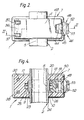
- the cover 11 has an essentially rectangular shape and that it can rotate around an axis 36 ( Figures 2 and 3) supported by the ends 37 of a pair of rods 38, each of which can slide inside a longitudinal housing inside the arm 17.
- Each rod 38 has, on the side opposite the end 37, a threaded section 39 (see FIG. 3) on which screws a nut 40.
- the housing of each rod 38 widens essentially at the height of the section 39, constituting a cylindrical chamber 41 which contains the helical spring 12 already mentioned, coaxial with the rod 38 and calibrated by tightening the nut 40.
- the cover 11 On the side opposite to that rotating around the axis 36, the cover 11 has a hook 44 capable of cooperating with a corresponding hook 45 disposed at the end of an arm 46 capable of pivoting around an axis 47 fixed transversely on the arm 18.
- the hook 45 of the pivoting arm 46 is essentially of trapezoidal shape and tapers towards the end, while the hook 44 is located below the housing 48, also of shaped trapezoidal and complementary to that of the hook 45, in order to facilitate the locking of the hook 45 on the hook 44.
- the pivoting arm 46 On the side opposite to that which includes the hook 45, the pivoting arm 46 has an end 49 which delimits a part of the housing of a helical spring 50.
- a spring is included between the end 49 of the pivoting arm 46 and the opposite surface of the arm 18, facing outwards and transmitting to the pivoting arm 49 an elastic thrust capable of causing the latter to rotate clockwise (see FIG. 3) in order to facilitate attachment between the hooks 44 of the cover 11 and 45 of the pivoting arm 46.
- the end 49 On the side opposite to that of the spring 50, the end 49 has a bulge 52 essentially forming a truncated pyramid on the surface of which is formed a circular, concave hollow location 53.
- the cover 11 has, on the side facing the housing 8 of the hollow body 7, a plurality of parallel longitudinal ribs 54, which each extend essentially from the end situated towards the axis 36 to the opposite end provided with the hook 44.
- each rib 54 has a profile essentially constituting an elliptical arc to complete and close the housing 8.
- the device 1 is used in the following way:
- the enclosure (2) is introduced into the housing 8, as shown in FIG. 1. Then the cover 11 is closed by pushing it until the hook 45 is locked on the hook 44 (see FIG. 2). Under these conditions, the cover 11 is held against the hollow body 7 on one side by the hook 44 and on the opposite side by the pin 36 and the rods 38.
- the device (1) is ready to be used as a detector for the presence of a gaseous fluid inside the part (5) of the enclosure (2).
- the transducer-transmitter 9 with a signal of predetermined frequency, for example ultrasonic, and to take note of the corresponding signal emitted by the transducer-receiver 10. Since, as we know, the amplitude of the signal emitted by the transducer 10 depends on the presence of gaseous fluid, for example very fine air bubbles, between the transducers 9 and 10, it will be sufficient to compare the effective value of such an amplitude with a reference value for detect the possible presence of gaseous fluid at the level of the intermediate zone (5).
- the device 1 makes it possible to detect either the presence of gaseous fluid in the liquid of the enclosure (2), or a lowering of the level of such a liquid below the zone placed under the control of the transducers 9 and 10.
Landscapes
- Health & Medical Sciences (AREA)
- Physics & Mathematics (AREA)
- Life Sciences & Earth Sciences (AREA)
- General Health & Medical Sciences (AREA)
- Pathology (AREA)
- Chemical & Material Sciences (AREA)
- Analytical Chemistry (AREA)
- Biochemistry (AREA)
- General Physics & Mathematics (AREA)
- Immunology (AREA)
- Vascular Medicine (AREA)
- Heart & Thoracic Surgery (AREA)
- Acoustics & Sound (AREA)
- Hematology (AREA)
- Engineering & Computer Science (AREA)
- Anesthesiology (AREA)
- Biomedical Technology (AREA)
- Cardiology (AREA)
- Animal Behavior & Ethology (AREA)
- Public Health (AREA)
- Veterinary Medicine (AREA)
- Investigating Or Analyzing Materials By The Use Of Ultrasonic Waves (AREA)
- Measurement Of Levels Of Liquids Or Fluent Solid Materials (AREA)
- Investigating Or Analysing Biological Materials (AREA)
- Ultra Sonic Daignosis Equipment (AREA)
- Measurement Of Velocity Or Position Using Acoustic Or Ultrasonic Waves (AREA)
Claims (19)
Applications Claiming Priority (2)
| Application Number | Priority Date | Filing Date | Title |
|---|---|---|---|
| IT5398784U | 1984-10-31 | ||
| IT8453987U IT8453987V0 (it) | 1984-10-31 | 1984-10-31 | Dispositivo rivelatore della presenza di fluido in corrispondenza di un prefissato livello di un contenitore di liquido |
Publications (3)
| Publication Number | Publication Date |
|---|---|
| EP0181272A2 EP0181272A2 (de) | 1986-05-14 |
| EP0181272A3 EP0181272A3 (en) | 1987-09-30 |
| EP0181272B1 true EP0181272B1 (de) | 1990-11-22 |
Family
ID=11286262
Family Applications (1)
| Application Number | Title | Priority Date | Filing Date |
|---|---|---|---|
| EP85420174A Expired - Lifetime EP0181272B1 (de) | 1984-10-31 | 1985-10-02 | Vorrichtung zur Anzeige von Blasen im Blut |
Country Status (6)
| Country | Link |
|---|---|
| US (1) | US4668945A (de) |
| EP (1) | EP0181272B1 (de) |
| JP (1) | JPS61109554A (de) |
| CA (1) | CA1256977A (de) |
| DE (2) | DE8521951U1 (de) |
| IT (1) | IT8453987V0 (de) |
Families Citing this family (46)
| Publication number | Priority date | Publication date | Assignee | Title |
|---|---|---|---|---|
| US4821558A (en) * | 1987-05-01 | 1989-04-18 | Abbott Laboratories | Ultrasonic detector |
| US4764166A (en) * | 1987-08-17 | 1988-08-16 | Fisher Scientific Company | Ultrasonic air-in-line detector |
| US4884065A (en) * | 1988-06-13 | 1989-11-28 | Pacesetter Infusion, Ltd. | Monitor for detecting tube position and air bubbles in tube |
| US4916915A (en) * | 1988-08-12 | 1990-04-17 | Murray Corporation | Method of and system for determining refrigerant/lubricant ratio within enclosed flow apparatus |
| US4964090A (en) * | 1989-07-19 | 1990-10-16 | Trw, Inc. | Ultrasonic fluid level sensor |
| US5176631A (en) * | 1989-09-05 | 1993-01-05 | Pacesetter Infusion, Ltd. | Ultrasonic air-in-line detector for detecting entrained air in a medication infusion system |
| US5000663A (en) * | 1989-09-05 | 1991-03-19 | Pacesetter Infusion, Ltd. | Automatic tubing lock for ultrasonic sensor interface |
| US5126616A (en) * | 1989-09-05 | 1992-06-30 | Pacesetter Infusion, Ltd. | Ultrasonic transducer electrical interface assembly |
| US5053747A (en) * | 1989-09-05 | 1991-10-01 | Pacesetter Infusion, Inc. | Ultrasonic air-in-line detector self-test technique |
| US5064412A (en) * | 1989-09-05 | 1991-11-12 | Pacesetter Infusion, Ltd. | Ultrasonic air-in-line detector for a medication infusion system |
| JPH03107758A (ja) * | 1989-09-21 | 1991-05-08 | Terumo Corp | 気泡検出センサ |
| US5125801A (en) * | 1990-02-02 | 1992-06-30 | Isco, Inc. | Pumping system |
| IT1238240B (it) * | 1990-02-08 | 1993-07-12 | Bellco Spa | Sistema per il rilevamento del passaggio di bolle d'aria in un gocciolatore di una apparecchiatura per trattamenti di dialisi. |
| US5351036A (en) * | 1991-12-10 | 1994-09-27 | Clark-Reliance Corporation | Microwave-based point liquid level monitoring system |
| FR2710538B1 (fr) * | 1993-09-30 | 1995-12-01 | Becton Dickinson Co | Procédé et dispositif de détection de bulles dans une ligne de perfusion. |
| DE19500154C1 (de) * | 1995-01-04 | 1996-10-17 | Fritz Giebler Gmbh | Infusionsschlauch für ein Infusionsgerät mit einem Blasendetektor |
| FR2729224A1 (fr) * | 1995-01-05 | 1996-07-12 | Debiotech Sa | Dispositif de controle de l'ecoulement d'un liquide dans une conduite tubulaire et notamment dans une pompe peristaltique |
| US5718507A (en) * | 1995-07-25 | 1998-02-17 | Gian; Michael | Dosifying apparatus for mixing a batch of mixed liquid product from separate bulk sources of supply of a liquid carrier and an additive |
| DE19538677C2 (de) * | 1995-10-17 | 1998-12-17 | Endress Hauser Gmbh Co | Anordnung zur Überwachung eines vorbestimmten Füllstands einer Flüssigkeit in einem Behälter |
| US6231320B1 (en) | 1998-06-12 | 2001-05-15 | Abbott Laboratories | Drug infusion pumping cassette latching mechanism |
| US6142008A (en) * | 1998-06-12 | 2000-11-07 | Abbott Laboratories | Air bubble sensor |
| US6250793B1 (en) * | 2000-05-23 | 2001-06-26 | Michael Gian | Animal feed additive application utilizing foam |
| DE20101082U1 (de) * | 2001-01-20 | 2002-05-29 | B. Braun Melsungen Ag, 34212 Melsungen | Ultraschallsensor zum Detektieren von Gasblasen |
| WO2007044799A2 (en) * | 2005-10-11 | 2007-04-19 | Be Intellectual Property, Inc. | Improved breathing mask and regulator for aircraft |
| US9026370B2 (en) | 2007-12-18 | 2015-05-05 | Hospira, Inc. | User interface improvements for medical devices |
| US8120500B2 (en) * | 2008-12-08 | 2012-02-21 | Ecolab Inc. | Acoustic fluid presence/absence detection |
| GB0920928D0 (en) | 2009-11-30 | 2010-01-13 | Morgan Electro Ceramics Ltd | Sensors for detecting gas in, and pressure of, a liquid |
| AU2012299169B2 (en) | 2011-08-19 | 2017-08-24 | Icu Medical, Inc. | Systems and methods for a graphical interface including a graphical representation of medical data |
| US10022498B2 (en) | 2011-12-16 | 2018-07-17 | Icu Medical, Inc. | System for monitoring and delivering medication to a patient and method of using the same to minimize the risks associated with automated therapy |
| JP6306566B2 (ja) | 2012-03-30 | 2018-04-04 | アイシーユー・メディカル・インコーポレーテッド | 注入システムのポンプ内の空気を検出するための空気検出システムおよび方法 |
| WO2014022513A1 (en) | 2012-07-31 | 2014-02-06 | Hospira, Inc. | Patient care system for critical medications |
| DE102013225100A1 (de) | 2012-12-10 | 2014-06-26 | Ifm Electronic Gmbh | Induktiver Näherungsschalter mit einem Ferritkern |
| AU2014268355B2 (en) | 2013-05-24 | 2018-06-14 | Icu Medical, Inc. | Multi-sensor infusion system for detecting air or an occlusion in the infusion system |
| WO2014194065A1 (en) | 2013-05-29 | 2014-12-04 | Hospira, Inc. | Infusion system and method of use which prevents over-saturation of an analog-to-digital converter |
| CA2913915C (en) | 2013-05-29 | 2022-03-29 | Hospira, Inc. | Infusion system which utilizes one or more sensors and additional information to make an air determination regarding the infusion system |
| ES2776363T3 (es) | 2014-02-28 | 2020-07-30 | Icu Medical Inc | Sistema de infusión y método que utiliza detección óptica de aire en línea de doble longitud de onda |
| US11344673B2 (en) | 2014-05-29 | 2022-05-31 | Icu Medical, Inc. | Infusion system and pump with configurable closed loop delivery rate catch-up |
| US11344668B2 (en) | 2014-12-19 | 2022-05-31 | Icu Medical, Inc. | Infusion system with concurrent TPN/insulin infusion |
| US10850024B2 (en) | 2015-03-02 | 2020-12-01 | Icu Medical, Inc. | Infusion system, device, and method having advanced infusion features |
| EP4085944A1 (de) | 2016-05-13 | 2022-11-09 | ICU Medical, Inc. | Infusionspumpensystem mit gemeinsamer leitung zur automatischen spülung |
| CA3027176A1 (en) | 2016-06-10 | 2017-12-14 | Icu Medical, Inc. | Acoustic flow sensor for continuous medication flow measurements and feedback control of infusion |
| JP7020869B2 (ja) * | 2017-11-10 | 2022-02-16 | マルヤス工業株式会社 | 気泡検出装置及び気泡検出方法 |
| US10089055B1 (en) | 2017-12-27 | 2018-10-02 | Icu Medical, Inc. | Synchronized display of screen content on networked devices |
| US11278671B2 (en) | 2019-12-04 | 2022-03-22 | Icu Medical, Inc. | Infusion pump with safety sequence keypad |
| CA3189781A1 (en) | 2020-07-21 | 2022-01-27 | Icu Medical, Inc. | Fluid transfer devices and methods of use |
| US11135360B1 (en) | 2020-12-07 | 2021-10-05 | Icu Medical, Inc. | Concurrent infusion with common line auto flush |
Family Cites Families (9)
| Publication number | Priority date | Publication date | Assignee | Title |
|---|---|---|---|---|
| US3411344A (en) * | 1964-11-02 | 1968-11-19 | William H Hopkins | Resonant frequency vibration testing method and apparatus |
| DE2240342B2 (de) * | 1972-08-17 | 1975-11-27 | B. Braun Melsungen Ag, 3508 Melsungen | Vorrichtung zur akustischen Erkennung von Gasblasen in Flüssigkeiten mit korpuskularen Bestandteilen |
| GB1418181A (en) * | 1973-02-27 | 1975-12-17 | Cole E M | Ultrasonic detection of inclusions in a fluid flowing within a tube |
| US3974681A (en) * | 1973-10-23 | 1976-08-17 | Jerry Namery | Ultrasonic bubble detector |
| US3935876A (en) * | 1974-11-15 | 1976-02-03 | Renal Systems, Inc. | Air leak detector |
| US4114144A (en) * | 1976-08-12 | 1978-09-12 | Imed Corporation | Automatic air-in-line fluid detector |
| CH649713A5 (en) * | 1980-09-13 | 1985-06-14 | Paul Eckli | Device for monitoring medical infusions |
| US4418565A (en) * | 1980-12-03 | 1983-12-06 | Baxter Travenol Laboratories, Inc. | Ultrasonic bubble detector |
| US4432231A (en) * | 1982-06-28 | 1984-02-21 | Baxter Travenol Laboratories, Inc. | Ultrasonic level detector |
-
1984
- 1984-10-31 IT IT8453987U patent/IT8453987V0/it unknown
-
1985
- 1985-07-30 DE DE8521951U patent/DE8521951U1/de not_active Expired
- 1985-10-02 DE DE8585420174T patent/DE3580651D1/de not_active Expired - Lifetime
- 1985-10-02 EP EP85420174A patent/EP0181272B1/de not_active Expired - Lifetime
- 1985-10-17 CA CA000493156A patent/CA1256977A/fr not_active Expired
- 1985-10-25 US US06/791,493 patent/US4668945A/en not_active Expired - Lifetime
- 1985-10-28 JP JP60239638A patent/JPS61109554A/ja active Pending
Also Published As
| Publication number | Publication date |
|---|---|
| DE3580651D1 (de) | 1991-01-03 |
| IT8453987V0 (it) | 1984-10-31 |
| CA1256977A (fr) | 1989-07-04 |
| US4668945A (en) | 1987-05-26 |
| DE8521951U1 (de) | 1985-11-14 |
| EP0181272A3 (en) | 1987-09-30 |
| EP0181272A2 (de) | 1986-05-14 |
| JPS61109554A (ja) | 1986-05-28 |
Similar Documents
| Publication | Publication Date | Title |
|---|---|---|
| EP0181272B1 (de) | Vorrichtung zur Anzeige von Blasen im Blut | |
| FR2665533A1 (fr) | Dispositif de mesure a distance de temperature et/ou de differences de temperature. | |
| EP1513221A1 (de) | Tragbares Armbandgerät mit elektrischem Verbindungselement durchs Gehäuse und Verfahren zur Montage des Verbindungselements | |
| FR2466931A1 (fr) | Transducteur electro-acoustique directionnel | |
| FR2549231A1 (fr) | Mecanisme pour detecter l'ecoulement d'un fluide dans un conduit | |
| EP0787974B1 (de) | Abgedichteter fotoelektrischer Sensor | |
| EP0686536B1 (de) | Hohles Gehäuse für eine Antriebsvorrichtung, insbesondere für Scheibenwischerantrieb, mit einem Verschlussdeckel | |
| EP0686537B1 (de) | Getriebemotor mit einem hohlen, mit einem Verschlussdeckel versehenen Gehäuse, insbesondere Scheibenwischer-Getriebemotor | |
| EP0479673A1 (de) | Getriebemotor mit seinem Gehäuseverschlussdeckel, insbesondere für eine Scheibenwischeranlage | |
| FR2561513A1 (fr) | Coupole de transmission de pression, notamment pour la transmission de la pression sanguine d'un patient a un transducteur | |
| FR2513752A1 (fr) | Dispositif de signalement d'inclinaison | |
| FR2478255A1 (fr) | Dispositif de detection par ultrasons de fermeture d'un clapet | |
| FR3062526A1 (fr) | Dispositif de connexion d'un conducteur | |
| FR2507282A1 (fr) | Dispositif d'articulation autour de deux directions et dispositif de visualisation comportant un tel dispositif d'articulation | |
| FR2932567A1 (fr) | Cellule de mesure pour appareil de detection de la presence d'un gaz dans une atmosphere | |
| FR2696775A1 (fr) | Perfectionnements aux poignées de porte à palettes basculantes. | |
| EP0082064B1 (de) | Manostat kleiner Bauweise und von leichter Ausführung und Montage | |
| EP0575212A1 (de) | Vorrichtung zur Beseitigung von auf der Schauglasinnenseite eines Totalisators geformtem Beschlag | |
| EP0252796B1 (de) | Griff für die Steuerung von Schaltern, insbesondere für Kraftfahrzeuge, und Führungsteil für die Verwirklichung dieses Griffs | |
| FR2527765A1 (fr) | Sonde pour appareil de mesure | |
| EP0178970A1 (de) | Ultraschallkabelplombe | |
| FR2618242A1 (fr) | Dispositif emetteur a cellule photovoltaique. | |
| FR2810735A1 (fr) | Perfectionnements apportes aux dispositifs de mesure de la masse volumique d'un liquide | |
| EP1538697A1 (de) | Tragbares Armbandgerät mit einer elektrischen Verbindungsvorrichtung durch das Gehäuse | |
| FR2473704A1 (fr) | Dispositif capteur de la presence d'un liquide a un niveau predetermine dans un reservoir |
Legal Events
| Date | Code | Title | Description |
|---|---|---|---|
| PUAI | Public reference made under article 153(3) epc to a published international application that has entered the european phase |
Free format text: ORIGINAL CODE: 0009012 |
|
| AK | Designated contracting states |
Kind code of ref document: A2 Designated state(s): BE CH DE FR GB IT LI NL SE |
|
| 17P | Request for examination filed |
Effective date: 19860910 |
|
| PUAL | Search report despatched |
Free format text: ORIGINAL CODE: 0009013 |
|
| AK | Designated contracting states |
Kind code of ref document: A3 Designated state(s): BE CH DE FR GB IT LI NL SE |
|
| 17Q | First examination report despatched |
Effective date: 19890928 |
|
| GRAA | (expected) grant |
Free format text: ORIGINAL CODE: 0009210 |
|
| AK | Designated contracting states |
Kind code of ref document: B1 Designated state(s): BE CH DE FR GB IT LI NL SE |
|
| GBT | Gb: translation of ep patent filed (gb section 77(6)(a)/1977) | ||
| REF | Corresponds to: |
Ref document number: 3580651 Country of ref document: DE Date of ref document: 19910103 |
|
| ITF | It: translation for a ep patent filed | ||
| PLBI | Opposition filed |
Free format text: ORIGINAL CODE: 0009260 |
|
| 26 | Opposition filed |
Opponent name: AKZO PATENTE GMBH Effective date: 19910821 |
|
| NLR1 | Nl: opposition has been filed with the epo |
Opponent name: AKZO PATENTE GMBH |
|
| PLBN | Opposition rejected |
Free format text: ORIGINAL CODE: 0009273 |
|
| STAA | Information on the status of an ep patent application or granted ep patent |
Free format text: STATUS: OPPOSITION REJECTED |
|
| ITTA | It: last paid annual fee | ||
| 27O | Opposition rejected |
Effective date: 19920925 |
|
| NLR2 | Nl: decision of opposition | ||
| EAL | Se: european patent in force in sweden |
Ref document number: 85420174.6 |
|
| REG | Reference to a national code |
Ref country code: GB Ref legal event code: IF02 |
|
| PGFP | Annual fee paid to national office [announced via postgrant information from national office to epo] |
Ref country code: CH Payment date: 20030110 Year of fee payment: 18 |
|
| PGFP | Annual fee paid to national office [announced via postgrant information from national office to epo] |
Ref country code: GB Payment date: 20030915 Year of fee payment: 19 |
|
| PGFP | Annual fee paid to national office [announced via postgrant information from national office to epo] |
Ref country code: NL Payment date: 20030916 Year of fee payment: 19 |
|
| PGFP | Annual fee paid to national office [announced via postgrant information from national office to epo] |
Ref country code: FR Payment date: 20031003 Year of fee payment: 19 |
|
| PGFP | Annual fee paid to national office [announced via postgrant information from national office to epo] |
Ref country code: SE Payment date: 20031006 Year of fee payment: 19 |
|
| PG25 | Lapsed in a contracting state [announced via postgrant information from national office to epo] |
Ref country code: LI Free format text: LAPSE BECAUSE OF NON-PAYMENT OF DUE FEES Effective date: 20031031 Ref country code: CH Free format text: LAPSE BECAUSE OF NON-PAYMENT OF DUE FEES Effective date: 20031031 |
|
| PGFP | Annual fee paid to national office [announced via postgrant information from national office to epo] |
Ref country code: BE Payment date: 20031203 Year of fee payment: 19 |
|
| REG | Reference to a national code |
Ref country code: CH Ref legal event code: PL |
|
| PG25 | Lapsed in a contracting state [announced via postgrant information from national office to epo] |
Ref country code: GB Free format text: LAPSE BECAUSE OF NON-PAYMENT OF DUE FEES Effective date: 20041002 |
|
| PG25 | Lapsed in a contracting state [announced via postgrant information from national office to epo] |
Ref country code: SE Free format text: LAPSE BECAUSE OF NON-PAYMENT OF DUE FEES Effective date: 20041003 |
|
| PGFP | Annual fee paid to national office [announced via postgrant information from national office to epo] |
Ref country code: DE Payment date: 20041029 Year of fee payment: 20 |
|
| PG25 | Lapsed in a contracting state [announced via postgrant information from national office to epo] |
Ref country code: BE Free format text: LAPSE BECAUSE OF NON-PAYMENT OF DUE FEES Effective date: 20041031 |
|
| BERE | Be: lapsed |
Owner name: *HOSPAL A.G. Effective date: 20041031 |
|
| PG25 | Lapsed in a contracting state [announced via postgrant information from national office to epo] |
Ref country code: NL Free format text: LAPSE BECAUSE OF NON-PAYMENT OF DUE FEES Effective date: 20050501 |
|
| GBPC | Gb: european patent ceased through non-payment of renewal fee |
Effective date: 20041002 |
|
| EUG | Se: european patent has lapsed | ||
| PG25 | Lapsed in a contracting state [announced via postgrant information from national office to epo] |
Ref country code: FR Free format text: LAPSE BECAUSE OF NON-PAYMENT OF DUE FEES Effective date: 20050630 |
|
| NLV4 | Nl: lapsed or anulled due to non-payment of the annual fee |
Effective date: 20050501 |
|
| REG | Reference to a national code |
Ref country code: FR Ref legal event code: ST |
|
| APAH | Appeal reference modified |
Free format text: ORIGINAL CODE: EPIDOSCREFNO |
|
| BERE | Be: lapsed |
Owner name: *HOSPAL A.G. Effective date: 20041031 |