EP0181272B1 - Device for detecting gas bubbles in blood - Google Patents
Device for detecting gas bubbles in blood Download PDFInfo
- Publication number
- EP0181272B1 EP0181272B1 EP85420174A EP85420174A EP0181272B1 EP 0181272 B1 EP0181272 B1 EP 0181272B1 EP 85420174 A EP85420174 A EP 85420174A EP 85420174 A EP85420174 A EP 85420174A EP 0181272 B1 EP0181272 B1 EP 0181272B1
- Authority
- EP
- European Patent Office
- Prior art keywords
- arm
- transducer
- transducers
- opposite
- housing
- Prior art date
- Legal status (The legal status is an assumption and is not a legal conclusion. Google has not performed a legal analysis and makes no representation as to the accuracy of the status listed.)
- Expired - Lifetime
Links
Images


Classifications
-
- A—HUMAN NECESSITIES
- A61—MEDICAL OR VETERINARY SCIENCE; HYGIENE
- A61M—DEVICES FOR INTRODUCING MEDIA INTO, OR ONTO, THE BODY; DEVICES FOR TRANSDUCING BODY MEDIA OR FOR TAKING MEDIA FROM THE BODY; DEVICES FOR PRODUCING OR ENDING SLEEP OR STUPOR
- A61M1/00—Suction or pumping devices for medical purposes; Devices for carrying-off, for treatment of, or for carrying-over, body-liquids; Drainage systems
- A61M1/36—Other treatment of blood in a by-pass of the natural circulatory system, e.g. temperature adaptation, irradiation ; Extra-corporeal blood circuits
- A61M1/3621—Extra-corporeal blood circuits
- A61M1/3626—Gas bubble detectors
-
- G—PHYSICS
- G01—MEASURING; TESTING
- G01N—INVESTIGATING OR ANALYSING MATERIALS BY DETERMINING THEIR CHEMICAL OR PHYSICAL PROPERTIES
- G01N29/00—Investigating or analysing materials by the use of ultrasonic, sonic or infrasonic waves; Visualisation of the interior of objects by transmitting ultrasonic or sonic waves through the object
- G01N29/02—Analysing fluids
- G01N29/024—Analysing fluids by measuring propagation velocity or propagation time of acoustic waves
-
- G—PHYSICS
- G01—MEASURING; TESTING
- G01N—INVESTIGATING OR ANALYSING MATERIALS BY DETERMINING THEIR CHEMICAL OR PHYSICAL PROPERTIES
- G01N29/00—Investigating or analysing materials by the use of ultrasonic, sonic or infrasonic waves; Visualisation of the interior of objects by transmitting ultrasonic or sonic waves through the object
- G01N29/02—Analysing fluids
- G01N29/032—Analysing fluids by measuring attenuation of acoustic waves
-
- G—PHYSICS
- G01—MEASURING; TESTING
- G01N—INVESTIGATING OR ANALYSING MATERIALS BY DETERMINING THEIR CHEMICAL OR PHYSICAL PROPERTIES
- G01N29/00—Investigating or analysing materials by the use of ultrasonic, sonic or infrasonic waves; Visualisation of the interior of objects by transmitting ultrasonic or sonic waves through the object
- G01N29/22—Details, e.g. general constructional or apparatus details
- G01N29/223—Supports, positioning or alignment in fixed situation
-
- G—PHYSICS
- G01—MEASURING; TESTING
- G01N—INVESTIGATING OR ANALYSING MATERIALS BY DETERMINING THEIR CHEMICAL OR PHYSICAL PROPERTIES
- G01N29/00—Investigating or analysing materials by the use of ultrasonic, sonic or infrasonic waves; Visualisation of the interior of objects by transmitting ultrasonic or sonic waves through the object
- G01N29/34—Generating the ultrasonic, sonic or infrasonic waves, e.g. electronic circuits specially adapted therefor
- G01N29/348—Generating the ultrasonic, sonic or infrasonic waves, e.g. electronic circuits specially adapted therefor with frequency characteristics, e.g. single frequency signals, chirp signals
-
- G—PHYSICS
- G01—MEASURING; TESTING
- G01N—INVESTIGATING OR ANALYSING MATERIALS BY DETERMINING THEIR CHEMICAL OR PHYSICAL PROPERTIES
- G01N2291/00—Indexing codes associated with group G01N29/00
- G01N2291/02—Indexing codes associated with the analysed material
- G01N2291/024—Mixtures
- G01N2291/02433—Gases in liquids, e.g. bubbles, foams
-
- G—PHYSICS
- G01—MEASURING; TESTING
- G01N—INVESTIGATING OR ANALYSING MATERIALS BY DETERMINING THEIR CHEMICAL OR PHYSICAL PROPERTIES
- G01N2291/00—Indexing codes associated with group G01N29/00
- G01N2291/10—Number of transducers
- G01N2291/102—Number of transducers one emitter, one receiver
-
- Y—GENERAL TAGGING OF NEW TECHNOLOGICAL DEVELOPMENTS; GENERAL TAGGING OF CROSS-SECTIONAL TECHNOLOGIES SPANNING OVER SEVERAL SECTIONS OF THE IPC; TECHNICAL SUBJECTS COVERED BY FORMER USPC CROSS-REFERENCE ART COLLECTIONS [XRACs] AND DIGESTS
- Y10—TECHNICAL SUBJECTS COVERED BY FORMER USPC
- Y10S—TECHNICAL SUBJECTS COVERED BY FORMER USPC CROSS-REFERENCE ART COLLECTIONS [XRACs] AND DIGESTS
- Y10S367/00—Communications, electrical: acoustic wave systems and devices
- Y10S367/908—Material level detection, e.g. liquid level
Definitions
- the present invention relates to a device for detecting the presence of a gaseous fluid in a liquid inside an enclosure below a predetermined level.
- This invention relates more particularly to a device using as means for detecting the presence of a gaseous fluid transducers capable of transmitting and receiving a signal sensitive to the presence of a gaseous fluid.
- piezoelectric transducers capable of transmitting and receiving signals at ultrasonic frequency, the propagation of which is strongly influenced by the presence, even in very small quantities, of a gaseous fluid.
- the use of a detector device in which only one of the transducers is removable, makes the operations for preparing the measurement more complex, since it is necessary to keep the spring tensioned with one hand and to place it correctly. the enclosure between the two transducers with the other hand.
- the object of the present invention is to provide a detection device which makes it possible to overcome the drawbacks linked to known devices of the types mentioned above and in particular a device which does not require the execution of precise guides for the support of the transducers and which is also easy to use.
- the reference 1 designates the assembly of a device detecting the presence of a gaseous fluid in relation to the predetermined level of the liquid in an enclosure 2.
- the enclosure 2 is essentially of tubular type with partially resiliently deformable walls. It has respectively an upper opening 3 widened for the entry of a liquid and a lower opening 4 which narrows for the exit of this same liquid.
- the enclosure 2 could be incorporated along an extracorporeal circuit of blood, in which case the liquid inside which it would be desired to detect the presence of gaseous fluid would be blood.
- the device 1 is capable of receiving the part 5 of the enclosure 2 placed in an intermediate position between the upper (3) and lower (4) openings of the enclosure (2) itself.
- the hollow body 7 has essentially the shape of a U and that it supports the transducers 9 and 10 respectively using arms 17 and 18.
- the transducer 9 is supported directly by the arm 17, while the transducer 10 is supported by an element 19 force-fitted inside a transverse hole 20 which the arm 18 presents.
- the housing 8 is constructed so as to be slightly elastic, the major axis of the ellipse being coincident with the axis of symmetry which connects the transducers 9 and 10.
- these transducers are covered with a layer 23, 24 of plastic, such as for example an epoxy resin.
- a layer 23, 24 of plastic such as for example an epoxy resin.
- each transducer 9 and 10 On the side opposite to the housing 8 of each transducer, there are two chambers 25, 26 which allow the piezoelectric transducers 9 and 10 to vibrate.
- the opposite faces of each transducer 9, 10 are connected by fine conductive wires to electrical cables 27, 28; in particular the junction between the conducting wires and the cables 27 and 28 takes place inside the respective chambers 29 and 30, formed in the intermediate zone 31 of the U-shaped body (7) and they are advantageously filled with a hardenable resin 32 , 33 in a suitable plastic.
- the cover 11 has an essentially rectangular shape and that it can rotate around an axis 36 ( Figures 2 and 3) supported by the ends 37 of a pair of rods 38, each of which can slide inside a longitudinal housing inside the arm 17.
- Each rod 38 has, on the side opposite the end 37, a threaded section 39 (see FIG. 3) on which screws a nut 40.
- the housing of each rod 38 widens essentially at the height of the section 39, constituting a cylindrical chamber 41 which contains the helical spring 12 already mentioned, coaxial with the rod 38 and calibrated by tightening the nut 40.
- the cover 11 On the side opposite to that rotating around the axis 36, the cover 11 has a hook 44 capable of cooperating with a corresponding hook 45 disposed at the end of an arm 46 capable of pivoting around an axis 47 fixed transversely on the arm 18.
- the hook 45 of the pivoting arm 46 is essentially of trapezoidal shape and tapers towards the end, while the hook 44 is located below the housing 48, also of shaped trapezoidal and complementary to that of the hook 45, in order to facilitate the locking of the hook 45 on the hook 44.
- the pivoting arm 46 On the side opposite to that which includes the hook 45, the pivoting arm 46 has an end 49 which delimits a part of the housing of a helical spring 50.
- a spring is included between the end 49 of the pivoting arm 46 and the opposite surface of the arm 18, facing outwards and transmitting to the pivoting arm 49 an elastic thrust capable of causing the latter to rotate clockwise (see FIG. 3) in order to facilitate attachment between the hooks 44 of the cover 11 and 45 of the pivoting arm 46.
- the end 49 On the side opposite to that of the spring 50, the end 49 has a bulge 52 essentially forming a truncated pyramid on the surface of which is formed a circular, concave hollow location 53.
- the cover 11 has, on the side facing the housing 8 of the hollow body 7, a plurality of parallel longitudinal ribs 54, which each extend essentially from the end situated towards the axis 36 to the opposite end provided with the hook 44.
- each rib 54 has a profile essentially constituting an elliptical arc to complete and close the housing 8.
- the device 1 is used in the following way:
- the enclosure (2) is introduced into the housing 8, as shown in FIG. 1. Then the cover 11 is closed by pushing it until the hook 45 is locked on the hook 44 (see FIG. 2). Under these conditions, the cover 11 is held against the hollow body 7 on one side by the hook 44 and on the opposite side by the pin 36 and the rods 38.
- the device (1) is ready to be used as a detector for the presence of a gaseous fluid inside the part (5) of the enclosure (2).
- the transducer-transmitter 9 with a signal of predetermined frequency, for example ultrasonic, and to take note of the corresponding signal emitted by the transducer-receiver 10. Since, as we know, the amplitude of the signal emitted by the transducer 10 depends on the presence of gaseous fluid, for example very fine air bubbles, between the transducers 9 and 10, it will be sufficient to compare the effective value of such an amplitude with a reference value for detect the possible presence of gaseous fluid at the level of the intermediate zone (5).
- the device 1 makes it possible to detect either the presence of gaseous fluid in the liquid of the enclosure (2), or a lowering of the level of such a liquid below the zone placed under the control of the transducers 9 and 10.
Description
La présente invention concerne un dispositif détecteur de la présence d'un fluide gazeux dans un liquide à l'intérieur d'une enceinte au-dessous d'un niveau prédéterminé. Cette invention concerne plus particulièrement un dispositif utilisant comme moyen de détection de la présence d'un fluide gazeux des transducteurs susceptibles de transmettre et de recevoir un signal sensible à la présence d'un fluide gazeux. Pour cela on préfère utiliser des transducteurs piézoélectriques aptes à transmettre et à recevoir des signaux à fréquence ultrasonique, dont la propagation est fortement influencée par la présence, même en très faibles quantités, d'un fluide gazeux.The present invention relates to a device for detecting the presence of a gaseous fluid in a liquid inside an enclosure below a predetermined level. This invention relates more particularly to a device using as means for detecting the presence of a gaseous fluid transducers capable of transmitting and receiving a signal sensitive to the presence of a gaseous fluid. For this it is preferred to use piezoelectric transducers capable of transmitting and receiving signals at ultrasonic frequency, the propagation of which is strongly influenced by the presence, even in very small quantities, of a gaseous fluid.
Afin d'éviter l'emprisonnement d'air entre les transducteurs et les surfaces opposées correspondantes de l'enceinte dans laquelle on doit effectuer la mesure, il est connu, par exemple par le FR 2 198 640, d'utiliser des moyens élastiques qui poussent les transducteurs contre les surfaces respectives opposées de l'enceinte. Ces moyens sont en général constitués par des ressorts hélicoïdaux logés à l'intérieur d'un corps supportant ladite enceinte, qui poussent élastiquement des éléments supports desdits transducteurs le long de glissières ménagées dans le corps de l'appareil. Dans une variante de réalisation, l'un des transducteurs est fixé au corps de l'appareil par un ressort hélicoïdal.In order to avoid trapping of air between the transducers and the corresponding opposite surfaces of the enclosure in which the measurement is to be made, it is known, for example from
Si les dispositifs connus mentionnés ci-dessus permettent effectivement de détecter la présence de fluide gazeux avec bonnes précision et fiabilité, ils sont particulièrement coûteux, essentiellement par le fait qu'ils exigent la réalisation de guides très précis pour les éléments support des transducteurs.If the known devices mentioned above actually make it possible to detect the presence of gaseous fluid with good precision and reliability, they are particularly expensive, essentially by the fact that they require the production of very precise guides for the support elements of the transducers.
En outre, l'utilisation d'un dispositif détecteur, dans lequel un seul des transducteurs est amovible, rend les opérations de préparation de la mesure plus complexes, puisqu'il est nécessaire de maintenir le ressort tendu d'une main et de placer correctement l'enceinte entre les deux transducteurs de l'autre main.In addition, the use of a detector device, in which only one of the transducers is removable, makes the operations for preparing the measurement more complex, since it is necessary to keep the spring tensioned with one hand and to place it correctly. the enclosure between the two transducers with the other hand.
Le but de la présente invention est de réaliser un dispositif de détection qui permette de surmonter les inconvénients liés aux dispositifs connus des types mentionnés ci-dessus et en particulier un dispositif qui ne nécessite pas l'exécution de guides précis pour le support des transducteurs et qui soit en outre facile à utiliser.The object of the present invention is to provide a detection device which makes it possible to overcome the drawbacks linked to known devices of the types mentioned above and in particular a device which does not require the execution of precise guides for the support of the transducers and which is also easy to use.
Ce but est atteint par la présente invention qui concerne un dispositif détecteur soit de la présence de gaz dans un liquide contenu dans une enceinte déformable et élastique, soit de l'abaissement du niveau d'un tel liquide en dessous d'une ligne prédéterminée à l'intérieur de l'enceinte, comprenant:
- un corps creux présentant un logement capable de recevoir une partie de ladite enceinte dans une position prédisposée par rapport à ladite ligne prédéterminée,
- une paire de transducteurs, respectivement transmetteur et récepteur d'un signal prédéterminé, fixés au dit corps creux en positions diamétralement opposées se faisant face, tournés vers ledit logement; ledit transducteur-transmetteur étant capable de coopérer avec ledit transducteur-transmetteur et à émettre un signal sensible à !a quantité de fluide gazeux interposée entre lesdits transducteurs,
caractérisé en ce qu'il comporte en outre un élément mobile relié au dit corps creux par des moyens élastiques et susceptible de transmettre une poussée radiale à ladite partie de l'enceinte capable de la déformer et de provoquer ainsi son adhésion en des zônes opposées contre les transducteurs sans inclusion d'air.
- a hollow body having a housing capable of receiving a part of said enclosure in a predisposed position relative to said predetermined line,
- a pair of transducers, respectively transmitter and receiver of a predetermined signal, fixed to said hollow body in diametrically opposite positions facing each other, facing towards said housing; said transducer-transmitter being capable of cooperating with said transducer-transmitter and of emitting a signal sensitive to the quantity of gaseous fluid interposed between said transducers,
characterized in that it further comprises a movable element connected to said hollow body by elastic means and capable of transmitting a radial thrust to said part of the enclosure capable of deforming it and thus causing it to adhere to opposite zones against transducers without air inclusion.
Pour mieux comprendre la présente invention, on va maintenant décrire une forme préférée de réalisation à titre d'exemple non limitatif et en référence aux dessins ci-joints dans lesquels:
- La figure 1 est la vue en élévation d'un dispositif de détection disposé autour d'une enceinte et illustré dans une position où il est prêt pour une mesure.
- La figure 2 représente le dispositif selon la figure 1 disposé pour détecter un fluide gazeux à l'intérieur de ladite enceinte.
- La figure 3 est une vue en coupe selon le plan III, III de la figure 2.
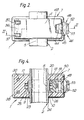
- La figure 4 est une vue en coupe selon le plan IV, IV de la figure 3.
- Figure 1 is the elevational view of a detection device arranged around an enclosure and illustrated in a position where it is ready for measurement.
- 2 shows the device according to Figure 1 arranged to detect a gaseous fluid inside said enclosure.
- FIG. 3 is a sectional view along plane III, III of FIG. 2.
- FIG. 4 is a sectional view along plane IV, IV of FIG. 3.
En se référant particulièrement aux figures 1 et 2, le repère 1 désigne l'ensemble d'un dispositif détecteur de la présence d'un fluide gazeux en relation avec le niveau prédéterminé du liquide dans une enceinte 2. L'enceinte 2 est essentiellement de type tubulaire avec des parois partiellement déformables de manière élastique. Elle présente respectivement une ouverture supérieure 3 élargie pour l'entrée d'un liquide et une ouverture inférieure 4 qui se rétrécit pour la sortie de ce même liquide. Advantageusement l'enceinte 2 pourrait être incorporée le long d'un circuit extra- corporel de sang, auquel cas le liquide à l'intérieur duquel on désirerait détecter la présence de fluide gazeux serait le sang.With particular reference to FIGS. 1 and 2, the
Le dispositif 1 est capable de recevoir la partie 5 de l'enceinte 2 placée en position intermédiaire entre les ouvertures supérieure (3) et inférieure (4) de l'enceinte (2) elle-même.The
En se référant plus particulièrement à la figure 3, le dispositif 1 comprend essentiellement:
- un corps creux 7 présentant un logement 8 susceptible de recevoir la partie intermédiaire 5 de l'enceinte 2.
- une paire de
transducteurs corps 7 en positions diamétralement opposées et se faisant face, tournés vers le logement 8; et - un couvercle 11 relié au
corps 7 par un ressort hélicoïdal 12 selon des dispositions décrites ci-après plus en détail et dont la fonction essentielle est de transmettre une poussée radiale sur lapartie 5 de l'enceinte 2 ayant pour but d'entraîner une déformation et en conséquence l'adhésion des faces opposées 13, 14 de lapartie 5 sur lestransducteurs 9 et 10 sans emprisonnement d'air entre les faces en contact.
- a
hollow body 7 having a housing 8 capable of receiving theintermediate part 5 of theenclosure 2. - a pair of
piezoelectric type transducers body 7 in diametrically opposite positions and facing each other, turned towards the housing 8; and - a cover 11 connected to the
body 7 by a helical spring 12 according to the arrangements described below in more detail and whose essential function is to transmit a radial thrust on thepart 5 of theenclosure 2 whose purpose is to cause a deformation and therefore membership oppositefaces part 5 on thetransducers
En examinant plus en détail le dispositif 1, on observe que le corps creux 7 a essentiellement la forme d'un U et qu'il supporte les transducteurs 9 et 10 resepctivement à l'aide de bras 17 et 18. En particulier le transducteur 9 est supporté directement par le bras 17, pendant que le transducteur 10 est supporté par un élément 19 emmanché de force à l'interieur d'un trou transversal 20 que présente le bras 18.By examining the
Le logement 8 est construit de manière à être légèrement élliqtique, le grand axe de l'ellipse étant confondu avec l'axe de symétrie qui relie les transducteurs 9 et 10. Sur les côtés tournés vers le logement 8, ces transducteurs sont recouverts d'une couche 23, 24 de matière plastique, telle que par exemple une résine époxy. En se reportant aux figures 3 et 4, on observe que la surface libre de chaque couche 23, 24 prend la configuration d'une selle de manière à créer une légère restriction de la partie du logement 8 en contact avec la partie 5 dans laquelle on désire détecter la présence de fluide gazeux.The housing 8 is constructed so as to be slightly elastic, the major axis of the ellipse being coincident with the axis of symmetry which connects the
Du coté opposé au logement 8 de chaque transducteur, se trouvent deux chambres 25, 26 qui permettent aux transducteurs piézoélectriques 9 et 10 de vibrer. Les faces opposées de chaque transducteur 9,10 sont reliées par des fils conducteurs fins à des câbles électriques 27, 28; en particulier la jonction entre les fils conducteurs et les câbles 27 et 28 a lieu à l'intérieur des chambres respectives 29 et 30, ménagées dans la zône intermédiaire 31 du corps en U (7) et elles sont avantageusement remplies avec une résine durcissable 32, 33 en une matière plastique convenable.On the side opposite to the housing 8 of each transducer, there are two
En se reportant aux figures 2, et 4, on observe que le couvercle 11 a une forme essentiellement rectangulaire et qu'il peut tourner autour d'un axe 36 (figures 2 et 3) supporté par les extrémités 37 d'une paire de tiges 38, dont chacune peut coulisser à l'intérieur d'un logement longitudinal à l'intérieur du bras 17. Chaque tige 38 présente, du coté opposé à l'extrémité 37, un tronçon fileté 39 (voir la figure 3) sur lequel se visse un écrou 40. Le logement de chaque tige 38 s'élargit essentiellement à hauteur de tronçon 39, constituant une chambre cylindrique 41 qui contient le ressort hélicoïdal 12 déjà mentionné, coaxial à la tige 38 et taré par serrage de l'écrou 40.Referring to Figures 2, and 4, it is observed that the cover 11 has an essentially rectangular shape and that it can rotate around an axis 36 (Figures 2 and 3) supported by the
Du coté opposé à celui tournant autour de l'axe 36 le couvercle 11 présente un crochet 44 susceptible de coopérer avec un crochet correspondant 45 disposé à l'extrémité d'un bras 46 susceptible de pivoter autour d'un axe 47 fixé transversalement sur le bras 18. En se référant à la figure 2, on voit que le crochet 45 du bras pivotant 46 est essentiellement de forme trapézoïdale et se rétrécit vers l'extrémité, alors que le crochet 44 est situé au dessous du logement 48, aussi de forme trapézoïdale et complémentaire à celle du crochet 45, afin de faciliter le verrouillage du crochet 45 sur le crochet 44.On the side opposite to that rotating around the
Du coté opposé à celui qui comporte le crochet 45, le bras pivotant 46 présente une extrémité 49 qui délimite une partie du logement d'un ressort hélicoïdal 50. Un tel ressort est compris entre l'extrémité 49 du bras pivotant 46 et la surface opposée du bras 18, tournée vers l'extérieur et transmettant au bras pivotant 49 une poussée élastique susceptible de faire tourner celui-ci dans le sens des aiguilles d'une montre (voir la figure 3) afin de faciliter l'accrochage entre les crochets 44 du couvercle 11 et 45 du bras pivotant 46.On the side opposite to that which includes the
Du coté opposé à celui du ressort 50, l'extrémité 49 présente un renflement 52 formant essentiellement un tronc de pyramide sur la surface de laquelle est ménagé un emplacement creux circulaire, concave 53.On the side opposite to that of the
On observe enfin, en se référant aux figures 1 et 3 que le couvercle 11 présente du coté tourné vers le logement 8 du corps creux 7, une pluralité de nervures longitudinales parallèles 54, qui s'étendent chacune essentiellement de l'extrémité située vers l'axe 36 jusqu'à l'extrémité opposée munie du crochet 44. Dans la partie faisant face au logement 8, chaque nervure 54 présente un profil constituant essentiellement un arc d'éllipse pour compléter et fermer le logement 8.Finally, with reference to FIGS. 1 and 3, it can be seen that the cover 11 has, on the side facing the housing 8 of the
Le dispositif 1 est utilisé de la manière suivante:The
Avant tout l'enceinte (2) est introduite dans le logement 8, comme représenté figure 1. Puis on ferme le couvercle 11 en le poussant jusqu'à ce que le crochet 45 se verrouille sur le crochet 44 (voir figure 2). Dans ces conditions le couvercle 11 est maintenu contre le corps creux 7 d'un coté par le crochet 44 et du coté opposé par l'axe 36 et les tiges 38.First of all, the enclosure (2) is introduced into the housing 8, as shown in FIG. 1. Then the cover 11 is closed by pushing it until the
Puisque celles-ci sont soumises à des efforts de traction axiaux élastiques sous l'effet des ressorts 12, il en résulte que le couvercle 11 transmet à la partie 5 de l'enceinte 2 un effort de compression radial par l'intermédiaire des profils elliptiques 55 des nervures longitudinales 54. De telles forces radiales entraînent la déformation de la partie 5 comportant les zones opposées 13,14 de manière à les faire adhérer parfaitement, sans emprisonner d'air, sur les faces opposées 23, 24 des transducteurs 9 et 10. La déformation de la partie 5 de l'enceinte 2 dans la direction des transducteurs 9 et 10 est favorisée par le fait que le logement 8 est partiellement élliptique et présente, comme déjà mentionné, le grand axe dans la direction des transducteurs.Since these are subjected to elastic axial tensile forces under the effect of the springs 12, it follows that the cover 11 transmits to the
Dans ces conditions, le dispositif (1) est prêt à être utilisé comme détecteur de la présence d'un fluide gazeux à l'intérieur de la partie (5) de l'enceinte (2). A ce sujet il est suffisant d'alimenter le transducteur-transmetteur 9 avec un signal de fréquence prédéterminée, par exemple ultrasonique, et de relever le signal correspondant émis par le transducteur-récepteur 10. Puisque, comme on le sait, l'amplitude du signal émis par le transducteur 10 dépend de la présence de fluide gazeux, par exemple de très fines bulles d'air, entre les transducteurs 9 et 10, il sera suffisant de comparer la valeur effective d'une telle amplitude avec une valeur de référence pour détecter la présence éventuelle de fluide gazeux à hauteur de la zône intermédiaire (5).Under these conditions, the device (1) is ready to be used as a detector for the presence of a gaseous fluid inside the part (5) of the enclosure (2). In this regard, it is sufficient to supply the transducer-
Il est évident que le dispositif 1 permet de détecter soit la présence de fluide gazeux dans le liquide de l'enceinte (2), soit un abaissement du niveau d'un tel liquide en dessous de la zône placée sous le contrôle des transducteurs 9 et 10.It is obvious that the
Dans le cas où l'on souhaite retirer l'enceinte 2, il suffira d'appuyer avec un doigt sur l'emplacement circulaire creux 53 à l'extrémité 49 du bras pivotant 46 (figure 3). Ce geste entraîne la rotation dans le sens inverse des aiguille d'une montre du bras pivotant 46 autour de l'axe 47 et compresse le ressort 50 jusqu'à ce que le crochet 45 libère le crochet 44 du couvercle 11. Celui-ci tourne partiellement autour de l'axe 36 sous l'effet de la réaction élastique exercée par la partie 5 de l'enceinte 2, puis il peut être ouvert complètement par l'opérateur jusqu'à la position indiquée en pointillés figure 3.In the case where it is desired to remove the
L'examen des caractéristiques du dispositif détecteur réalisé selon la présente invention permet de mettre en évidence les avantages obtenus. Tout particulièrement la réalisation de guides précis pour les éléments support des transducteurs piézoélectriques n'est pas nécessaire puisqu'ils sont fixés sur le corps creux 7. Celui-ci peut être moulé par injection, ce qui contribue à réduire le coût du dispositif 1. D'autre part, les opérations à effectuer pour disposer l'enceinte 2 dans le logement 8 puis pour fermer le couvercle 11 sont élémentaires et peuvent être facilement exécutées d'une seule main.Examination of the characteristics of the detector device produced according to the present invention makes it possible to highlight the advantages obtained. In particular, the production of precise guides for the support elements of the piezoelectric transducers is not necessary since they are fixed to the
Enfin il est clair que diverses modifications et variantes de réalisation peuvent être apportées par le technicien au dispositif 1 décrit ci-avant sous pour cela sortir du cadre de la présente invention, tel que défini par les revendications suivantes.Finally, it is clear that various modifications and variant embodiments can be made by the technician to the
Claims (19)
characterized in that it comprises, moreover, a movable element (11) connected to the said hollow body (7) by elastic means (12) and capable of transmitting a radial thrust to the said portion (5) of the vessel (2), capable of deforming it and of thus producing its adhesion in opposite zones (13, 14) to the transducers (9, 10) without the inclusion of air.
Applications Claiming Priority (2)
| Application Number | Priority Date | Filing Date | Title |
|---|---|---|---|
| IT5398784U | 1984-10-31 | ||
| IT8453987U IT8453987V0 (en) | 1984-10-31 | 1984-10-31 | DETECTOR DEVICE FOR THE PRESENCE OF FLUID IN CORRESPONDENCE WITH A PREFIXED LEVEL OF A LIQUID CONTAINER |
Publications (3)
| Publication Number | Publication Date |
|---|---|
| EP0181272A2 EP0181272A2 (en) | 1986-05-14 |
| EP0181272A3 EP0181272A3 (en) | 1987-09-30 |
| EP0181272B1 true EP0181272B1 (en) | 1990-11-22 |
Family
ID=11286262
Family Applications (1)
| Application Number | Title | Priority Date | Filing Date |
|---|---|---|---|
| EP85420174A Expired - Lifetime EP0181272B1 (en) | 1984-10-31 | 1985-10-02 | Device for detecting gas bubbles in blood |
Country Status (6)
| Country | Link |
|---|---|
| US (1) | US4668945A (en) |
| EP (1) | EP0181272B1 (en) |
| JP (1) | JPS61109554A (en) |
| CA (1) | CA1256977A (en) |
| DE (2) | DE8521951U1 (en) |
| IT (1) | IT8453987V0 (en) |
Families Citing this family (46)
| Publication number | Priority date | Publication date | Assignee | Title |
|---|---|---|---|---|
| US4821558A (en) * | 1987-05-01 | 1989-04-18 | Abbott Laboratories | Ultrasonic detector |
| US4764166A (en) * | 1987-08-17 | 1988-08-16 | Fisher Scientific Company | Ultrasonic air-in-line detector |
| US4884065A (en) * | 1988-06-13 | 1989-11-28 | Pacesetter Infusion, Ltd. | Monitor for detecting tube position and air bubbles in tube |
| US4916915A (en) * | 1988-08-12 | 1990-04-17 | Murray Corporation | Method of and system for determining refrigerant/lubricant ratio within enclosed flow apparatus |
| US4964090A (en) * | 1989-07-19 | 1990-10-16 | Trw, Inc. | Ultrasonic fluid level sensor |
| US5176631A (en) * | 1989-09-05 | 1993-01-05 | Pacesetter Infusion, Ltd. | Ultrasonic air-in-line detector for detecting entrained air in a medication infusion system |
| US5000663A (en) * | 1989-09-05 | 1991-03-19 | Pacesetter Infusion, Ltd. | Automatic tubing lock for ultrasonic sensor interface |
| US5126616A (en) * | 1989-09-05 | 1992-06-30 | Pacesetter Infusion, Ltd. | Ultrasonic transducer electrical interface assembly |
| US5053747A (en) * | 1989-09-05 | 1991-10-01 | Pacesetter Infusion, Inc. | Ultrasonic air-in-line detector self-test technique |
| US5064412A (en) * | 1989-09-05 | 1991-11-12 | Pacesetter Infusion, Ltd. | Ultrasonic air-in-line detector for a medication infusion system |
| JPH03107758A (en) * | 1989-09-21 | 1991-05-08 | Terumo Corp | Air bubble detection sensor |
| US5125801A (en) * | 1990-02-02 | 1992-06-30 | Isco, Inc. | Pumping system |
| IT1238240B (en) * | 1990-02-08 | 1993-07-12 | Bellco Spa | SYSTEM FOR DETECTING THE PASSAGE OF AIR BUBBLES IN A DRIPPER OF AN EQUIPMENT FOR DIALYSIS TREATMENTS. |
| US5351036A (en) * | 1991-12-10 | 1994-09-27 | Clark-Reliance Corporation | Microwave-based point liquid level monitoring system |
| FR2710538B1 (en) * | 1993-09-30 | 1995-12-01 | Becton Dickinson Co | Method and device for detecting bubbles in an infusion line. |
| DE19500154C1 (en) * | 1995-01-04 | 1996-10-17 | Fritz Giebler Gmbh | Infusion tube for an infusion device with a bubble detector |
| FR2729224A1 (en) * | 1995-01-05 | 1996-07-12 | Debiotech Sa | DEVICE FOR CONTROLLING THE FLOW OF A LIQUID IN A TUBULAR DUCT AND IN PARTICULAR IN A PERISTALTIC PUMP |
| US5718507A (en) * | 1995-07-25 | 1998-02-17 | Gian; Michael | Dosifying apparatus for mixing a batch of mixed liquid product from separate bulk sources of supply of a liquid carrier and an additive |
| DE19538677C2 (en) * | 1995-10-17 | 1998-12-17 | Endress Hauser Gmbh Co | Arrangement for monitoring a predetermined fill level of a liquid in a container |
| US6231320B1 (en) | 1998-06-12 | 2001-05-15 | Abbott Laboratories | Drug infusion pumping cassette latching mechanism |
| US6142008A (en) * | 1998-06-12 | 2000-11-07 | Abbott Laboratories | Air bubble sensor |
| US6250793B1 (en) * | 2000-05-23 | 2001-06-26 | Michael Gian | Animal feed additive application utilizing foam |
| DE20101082U1 (en) * | 2001-01-20 | 2002-05-29 | Braun Melsungen Ag | Ultrasonic sensor for the detection of gas bubbles |
| WO2007044799A2 (en) * | 2005-10-11 | 2007-04-19 | Be Intellectual Property, Inc. | Improved breathing mask and regulator for aircraft |
| US8517990B2 (en) | 2007-12-18 | 2013-08-27 | Hospira, Inc. | User interface improvements for medical devices |
| US8120500B2 (en) * | 2008-12-08 | 2012-02-21 | Ecolab Inc. | Acoustic fluid presence/absence detection |
| GB0920928D0 (en) | 2009-11-30 | 2010-01-13 | Morgan Electro Ceramics Ltd | Sensors for detecting gas in, and pressure of, a liquid |
| CA2844807C (en) | 2011-08-19 | 2022-07-26 | Hospira, Inc. | Systems and methods for a graphical interface including a graphical representation of medical data |
| US10022498B2 (en) | 2011-12-16 | 2018-07-17 | Icu Medical, Inc. | System for monitoring and delivering medication to a patient and method of using the same to minimize the risks associated with automated therapy |
| JP6306566B2 (en) | 2012-03-30 | 2018-04-04 | アイシーユー・メディカル・インコーポレーテッド | Air detection system and method for detecting air in an infusion system pump |
| ES2743160T3 (en) | 2012-07-31 | 2020-02-18 | Icu Medical Inc | Patient care system for critical medications |
| EP2741419B1 (en) | 2012-12-10 | 2015-01-21 | ifm electronic gmbh | Inductive proximity switch |
| WO2014190264A1 (en) | 2013-05-24 | 2014-11-27 | Hospira, Inc. | Multi-sensor infusion system for detecting air or an occlusion in the infusion system |
| AU2014274122A1 (en) | 2013-05-29 | 2016-01-21 | Icu Medical, Inc. | Infusion system and method of use which prevents over-saturation of an analog-to-digital converter |
| ES2838450T3 (en) | 2013-05-29 | 2021-07-02 | Icu Medical Inc | Infusion set that uses one or more sensors and additional information to make an air determination relative to the infusion set |
| JP6636442B2 (en) | 2014-02-28 | 2020-01-29 | アイシーユー・メディカル・インコーポレーテッド | Infusion systems and methods utilizing dual wavelength optical in-pipe air detection |
| AU2015266706B2 (en) | 2014-05-29 | 2020-01-30 | Icu Medical, Inc. | Infusion system and pump with configurable closed loop delivery rate catch-up |
| US11344668B2 (en) | 2014-12-19 | 2022-05-31 | Icu Medical, Inc. | Infusion system with concurrent TPN/insulin infusion |
| US10850024B2 (en) | 2015-03-02 | 2020-12-01 | Icu Medical, Inc. | Infusion system, device, and method having advanced infusion features |
| EP3454922B1 (en) | 2016-05-13 | 2022-04-06 | ICU Medical, Inc. | Infusion pump system with common line auto flush |
| CA3027176A1 (en) | 2016-06-10 | 2017-12-14 | Icu Medical, Inc. | Acoustic flow sensor for continuous medication flow measurements and feedback control of infusion |
| JP7020869B2 (en) * | 2017-11-10 | 2022-02-16 | マルヤス工業株式会社 | Bubble detection device and bubble detection method |
| US10089055B1 (en) | 2017-12-27 | 2018-10-02 | Icu Medical, Inc. | Synchronized display of screen content on networked devices |
| US11278671B2 (en) | 2019-12-04 | 2022-03-22 | Icu Medical, Inc. | Infusion pump with safety sequence keypad |
| WO2022020184A1 (en) | 2020-07-21 | 2022-01-27 | Icu Medical, Inc. | Fluid transfer devices and methods of use |
| US11135360B1 (en) | 2020-12-07 | 2021-10-05 | Icu Medical, Inc. | Concurrent infusion with common line auto flush |
Family Cites Families (9)
| Publication number | Priority date | Publication date | Assignee | Title |
|---|---|---|---|---|
| US3411344A (en) * | 1964-11-02 | 1968-11-19 | William H Hopkins | Resonant frequency vibration testing method and apparatus |
| DE2240342B2 (en) * | 1972-08-17 | 1975-11-27 | B. Braun Melsungen Ag, 3508 Melsungen | Device for acoustic detection of gas bubbles in liquids with corpuscular components |
| GB1418181A (en) * | 1973-02-27 | 1975-12-17 | Cole E M | Ultrasonic detection of inclusions in a fluid flowing within a tube |
| US3974681A (en) * | 1973-10-23 | 1976-08-17 | Jerry Namery | Ultrasonic bubble detector |
| US3935876A (en) * | 1974-11-15 | 1976-02-03 | Renal Systems, Inc. | Air leak detector |
| US4114144A (en) * | 1976-08-12 | 1978-09-12 | Imed Corporation | Automatic air-in-line fluid detector |
| CH649713A5 (en) * | 1980-09-13 | 1985-06-14 | Paul Eckli | Device for monitoring medical infusions |
| US4418565A (en) * | 1980-12-03 | 1983-12-06 | Baxter Travenol Laboratories, Inc. | Ultrasonic bubble detector |
| US4432231A (en) * | 1982-06-28 | 1984-02-21 | Baxter Travenol Laboratories, Inc. | Ultrasonic level detector |
-
1984
- 1984-10-31 IT IT8453987U patent/IT8453987V0/en unknown
-
1985
- 1985-07-30 DE DE8521951U patent/DE8521951U1/en not_active Expired
- 1985-10-02 DE DE8585420174T patent/DE3580651D1/en not_active Expired - Lifetime
- 1985-10-02 EP EP85420174A patent/EP0181272B1/en not_active Expired - Lifetime
- 1985-10-17 CA CA000493156A patent/CA1256977A/en not_active Expired
- 1985-10-25 US US06/791,493 patent/US4668945A/en not_active Expired - Lifetime
- 1985-10-28 JP JP60239638A patent/JPS61109554A/en active Pending
Also Published As
| Publication number | Publication date |
|---|---|
| EP0181272A2 (en) | 1986-05-14 |
| EP0181272A3 (en) | 1987-09-30 |
| DE3580651D1 (en) | 1991-01-03 |
| DE8521951U1 (en) | 1985-11-14 |
| JPS61109554A (en) | 1986-05-28 |
| US4668945A (en) | 1987-05-26 |
| CA1256977A (en) | 1989-07-04 |
| IT8453987V0 (en) | 1984-10-31 |
Similar Documents
| Publication | Publication Date | Title |
|---|---|---|
| EP0181272B1 (en) | Device for detecting gas bubbles in blood | |
| FR2665533A1 (en) | DEVICE FOR REMOTE MEASUREMENT OF TEMPERATURE AND / OR TEMPERATURE DIFFERENCES. | |
| EP0323779A1 (en) | Dispensing closure for a fluid or viscous products, and container provided with such a device | |
| EP0464767A1 (en) | Device composed of two elements jointed on a hinge and electrically connected | |
| EP1513221A1 (en) | Portable object with bracelet and electrical connecting flange penetrating the casing, and method of mounting the flange | |
| FR2466931A1 (en) | DIRECTIONAL ELECTRO-ACOUSTIC TRANSDUCER | |
| FR2549231A1 (en) | MECHANISM FOR DETECTING THE FLOW OF A FLUID IN A CONDUIT | |
| EP0686536B1 (en) | A motorized reduction gear unit having a hollow casing with a cover plate, especially for a vehicle screen wiper drive unit | |
| EP0787974B1 (en) | Sealed photoelectric sensor | |
| EP0686537B1 (en) | Geared motor having a hollow housing equipped with a closure plate, especially a geared motor for a wiping system | |
| EP0479673A1 (en) | Geared motor with its housing closure cover, especially for a windscreenwiper | |
| FR2561513A1 (en) | PRESSURE TRANSMISSION COVER, IN PARTICULAR FOR TRANSMITTING THE BLOOD PRESSURE OF A PATIENT TO A TRANSDUCER | |
| FR2513752A1 (en) | INCLINATION REPORTING DEVICE | |
| FR3062526A1 (en) | DEVICE FOR CONNECTING A DRIVER | |
| FR2932567A1 (en) | MEASURING CELL FOR APPARATUS FOR DETECTING THE PRESENCE OF A GAS IN AN ATMOSPHERE | |
| FR2696775A1 (en) | Improvements to tilting pallet door handles. | |
| EP0575212A1 (en) | Device to eliminate condensation from the inside of the window of a totalizer | |
| EP0252796B1 (en) | Handle for the control of switches especially for motor vehicles and guiding means for the realization of the handle | |
| EP0178970A1 (en) | Ultrasonic cable seal | |
| FR2618242A1 (en) | TRANSMITTING DEVICE WITH PHOTOVOLTAIC CELL. | |
| FR2810735A1 (en) | Instrument for measuring density of liquid, comprises chamber with sealed walls one of which is connected solidly to mobile part of strain gauge while the other is attached to the fixed portion | |
| EP1538697A1 (en) | Portable device with bracelet having electrical connecting means through the housing | |
| FR2473704A1 (en) | Liq. level detector for IC engine cooling system - comprises float attached to vertical shaft moving magnet into contact with reed switch | |
| FR3028199A1 (en) | ELECTROPORTATIVE MOTORIZED TOOL WITH ERGONOMIC CONTROL. | |
| FR2621113A1 (en) | Measurement instrument, in particular for games of bowls (boules) |
Legal Events
| Date | Code | Title | Description |
|---|---|---|---|
| PUAI | Public reference made under article 153(3) epc to a published international application that has entered the european phase |
Free format text: ORIGINAL CODE: 0009012 |
|
| AK | Designated contracting states |
Kind code of ref document: A2 Designated state(s): BE CH DE FR GB IT LI NL SE |
|
| 17P | Request for examination filed |
Effective date: 19860910 |
|
| PUAL | Search report despatched |
Free format text: ORIGINAL CODE: 0009013 |
|
| AK | Designated contracting states |
Kind code of ref document: A3 Designated state(s): BE CH DE FR GB IT LI NL SE |
|
| 17Q | First examination report despatched |
Effective date: 19890928 |
|
| GRAA | (expected) grant |
Free format text: ORIGINAL CODE: 0009210 |
|
| AK | Designated contracting states |
Kind code of ref document: B1 Designated state(s): BE CH DE FR GB IT LI NL SE |
|
| GBT | Gb: translation of ep patent filed (gb section 77(6)(a)/1977) | ||
| REF | Corresponds to: |
Ref document number: 3580651 Country of ref document: DE Date of ref document: 19910103 |
|
| ITF | It: translation for a ep patent filed |
Owner name: STUDIO TORTA SOCIETA' SEMPLICE |
|
| PLBI | Opposition filed |
Free format text: ORIGINAL CODE: 0009260 |
|
| 26 | Opposition filed |
Opponent name: AKZO PATENTE GMBH Effective date: 19910821 |
|
| NLR1 | Nl: opposition has been filed with the epo |
Opponent name: AKZO PATENTE GMBH |
|
| PLBN | Opposition rejected |
Free format text: ORIGINAL CODE: 0009273 |
|
| STAA | Information on the status of an ep patent application or granted ep patent |
Free format text: STATUS: OPPOSITION REJECTED |
|
| ITTA | It: last paid annual fee | ||
| 27O | Opposition rejected |
Effective date: 19920925 |
|
| NLR2 | Nl: decision of opposition | ||
| EAL | Se: european patent in force in sweden |
Ref document number: 85420174.6 |
|
| REG | Reference to a national code |
Ref country code: GB Ref legal event code: IF02 |
|
| PGFP | Annual fee paid to national office [announced via postgrant information from national office to epo] |
Ref country code: CH Payment date: 20030110 Year of fee payment: 18 |
|
| PGFP | Annual fee paid to national office [announced via postgrant information from national office to epo] |
Ref country code: GB Payment date: 20030915 Year of fee payment: 19 |
|
| PGFP | Annual fee paid to national office [announced via postgrant information from national office to epo] |
Ref country code: NL Payment date: 20030916 Year of fee payment: 19 |
|
| PGFP | Annual fee paid to national office [announced via postgrant information from national office to epo] |
Ref country code: FR Payment date: 20031003 Year of fee payment: 19 |
|
| PGFP | Annual fee paid to national office [announced via postgrant information from national office to epo] |
Ref country code: SE Payment date: 20031006 Year of fee payment: 19 |
|
| PG25 | Lapsed in a contracting state [announced via postgrant information from national office to epo] |
Ref country code: LI Free format text: LAPSE BECAUSE OF NON-PAYMENT OF DUE FEES Effective date: 20031031 Ref country code: CH Free format text: LAPSE BECAUSE OF NON-PAYMENT OF DUE FEES Effective date: 20031031 |
|
| PGFP | Annual fee paid to national office [announced via postgrant information from national office to epo] |
Ref country code: BE Payment date: 20031203 Year of fee payment: 19 |
|
| REG | Reference to a national code |
Ref country code: CH Ref legal event code: PL |
|
| PG25 | Lapsed in a contracting state [announced via postgrant information from national office to epo] |
Ref country code: GB Free format text: LAPSE BECAUSE OF NON-PAYMENT OF DUE FEES Effective date: 20041002 |
|
| PG25 | Lapsed in a contracting state [announced via postgrant information from national office to epo] |
Ref country code: SE Free format text: LAPSE BECAUSE OF NON-PAYMENT OF DUE FEES Effective date: 20041003 |
|
| PGFP | Annual fee paid to national office [announced via postgrant information from national office to epo] |
Ref country code: DE Payment date: 20041029 Year of fee payment: 20 |
|
| PG25 | Lapsed in a contracting state [announced via postgrant information from national office to epo] |
Ref country code: BE Free format text: LAPSE BECAUSE OF NON-PAYMENT OF DUE FEES Effective date: 20041031 |
|
| BERE | Be: lapsed |
Owner name: *HOSPAL A.G. Effective date: 20041031 |
|
| PG25 | Lapsed in a contracting state [announced via postgrant information from national office to epo] |
Ref country code: NL Free format text: LAPSE BECAUSE OF NON-PAYMENT OF DUE FEES Effective date: 20050501 |
|
| GBPC | Gb: european patent ceased through non-payment of renewal fee |
Effective date: 20041002 |
|
| EUG | Se: european patent has lapsed | ||
| PG25 | Lapsed in a contracting state [announced via postgrant information from national office to epo] |
Ref country code: FR Free format text: LAPSE BECAUSE OF NON-PAYMENT OF DUE FEES Effective date: 20050630 |
|
| NLV4 | Nl: lapsed or anulled due to non-payment of the annual fee |
Effective date: 20050501 |
|
| REG | Reference to a national code |
Ref country code: FR Ref legal event code: ST |
|
| APAH | Appeal reference modified |
Free format text: ORIGINAL CODE: EPIDOSCREFNO |
|
| BERE | Be: lapsed |
Owner name: *HOSPAL A.G. Effective date: 20041031 |