EP1538697A1 - Tragbares Armbandgerät mit einer elektrischen Verbindungsvorrichtung durch das Gehäuse - Google Patents
Tragbares Armbandgerät mit einer elektrischen Verbindungsvorrichtung durch das Gehäuse Download PDFInfo
- Publication number
- EP1538697A1 EP1538697A1 EP03026428A EP03026428A EP1538697A1 EP 1538697 A1 EP1538697 A1 EP 1538697A1 EP 03026428 A EP03026428 A EP 03026428A EP 03026428 A EP03026428 A EP 03026428A EP 1538697 A1 EP1538697 A1 EP 1538697A1
- Authority
- EP
- European Patent Office
- Prior art keywords
- housing
- connector
- wall
- conductive track
- portable object
- Prior art date
- Legal status (The legal status is an assumption and is not a legal conclusion. Google has not performed a legal analysis and makes no representation as to the accuracy of the status listed.)
- Granted
Links
- 239000002184 metal Substances 0.000 claims description 17
- 230000000295 complement effect Effects 0.000 claims description 14
- 230000007613 environmental effect Effects 0.000 claims description 4
- 238000003780 insertion Methods 0.000 claims description 4
- 230000037431 insertion Effects 0.000 claims description 4
- 229910001220 stainless steel Inorganic materials 0.000 claims description 4
- 239000010935 stainless steel Substances 0.000 claims description 4
- 230000001681 protective effect Effects 0.000 claims description 3
- 239000011345 viscous material Substances 0.000 claims description 3
- 230000005540 biological transmission Effects 0.000 claims description 2
- 239000007769 metal material Substances 0.000 claims description 2
- 239000004020 conductor Substances 0.000 abstract description 11
- 239000000463 material Substances 0.000 description 9
- 238000007789 sealing Methods 0.000 description 5
- 239000004033 plastic Substances 0.000 description 4
- 229920003023 plastic Polymers 0.000 description 4
- 238000009413 insulation Methods 0.000 description 2
- 229920000265 Polyparaphenylene Polymers 0.000 description 1
- UCKMPCXJQFINFW-UHFFFAOYSA-N Sulphide Chemical compound [S-2] UCKMPCXJQFINFW-UHFFFAOYSA-N 0.000 description 1
- 230000004308 accommodation Effects 0.000 description 1
- 230000007797 corrosion Effects 0.000 description 1
- 238000005260 corrosion Methods 0.000 description 1
- 230000000694 effects Effects 0.000 description 1
- 229920001971 elastomer Polymers 0.000 description 1
- 239000000806 elastomer Substances 0.000 description 1
- 230000006353 environmental stress Effects 0.000 description 1
- 239000003365 glass fiber Substances 0.000 description 1
- 239000004973 liquid crystal related substance Substances 0.000 description 1
- 238000012423 maintenance Methods 0.000 description 1
- 230000002093 peripheral effect Effects 0.000 description 1
- -1 polyphenylene Polymers 0.000 description 1
- 229920002635 polyurethane Polymers 0.000 description 1
- 239000004814 polyurethane Substances 0.000 description 1
- 230000035882 stress Effects 0.000 description 1
Images


Classifications
-
- H—ELECTRICITY
- H01—ELECTRIC ELEMENTS
- H01Q—ANTENNAS, i.e. RADIO AERIALS
- H01Q1/00—Details of, or arrangements associated with, antennas
- H01Q1/27—Adaptation for use in or on movable bodies
- H01Q1/273—Adaptation for carrying or wearing by persons or animals
-
- G—PHYSICS
- G04—HOROLOGY
- G04G—ELECTRONIC TIME-PIECES
- G04G17/00—Structural details; Housings
- G04G17/02—Component assemblies
- G04G17/04—Mounting of electronic components
-
- G—PHYSICS
- G04—HOROLOGY
- G04R—RADIO-CONTROLLED TIME-PIECES
- G04R60/00—Constructional details
- G04R60/04—Antennas attached to or integrated in watch bracelets
Definitions
- the present invention relates to a portable object with a bracelet provided with means electrical connection through the housing.
- the portable object essentially comprises the housing in which is disposed at least one electronic circuit, an attached bracelet to the housing, and the electrical connection means for electrically connecting at least a conductive track of the bracelet to at least one contact terminal of the circuit electronic.
- the term "means of connection” any conductor or set of conductors to ensure electrical connection between at least one contact terminal of an electronic circuit and at less a conductive track disposed in the bracelet.
- the conductive track can be in the form of a conductive wire or a conductive blade. This conductive track may be an antenna for transmitting and receiving signals or electrically connect an electrical component contained in the bracelet and the circuit electronic in the case.
- the portable object is made in the form a portable electronic instrument in the form of a wristwatch.
- This wristwatch may comprise receiving means and / or radiofrequency signals if the conductive track of the bracelet defines a antenna.
- the electronic circuit for processing electrical signals manages the transmission or reception of information signals by the antenna.
- European Patent No. 0 631 341 describes an electronic instrument of the type wristwatch having an antenna housed in the bracelet and connected to a electronic circuit for processing the signals received by the antenna.
- the circuit electronic processing is arranged inside the housing of the instrument on a printed circuit board.
- Connection pads are provided on a region peripheral of the printed circuit board to allow the establishment of a electrical connection between the electronic signal processing circuit and the connection terminals of the antenna which passes through a side wall of the housing.
- it is intended to employ a spring blade-type connector attached to the printed circuit board for each terminal of the antenna, on which support an electrical conductor connected to one of the terminals of the antenna.
- Each conductor connected to an antenna terminal must pass through the side wall in order to lean on the spring blade to establish the electrical contact.
- An annular seal seal is provided around said conductor in the passageway through the wall lateral.
- a disadvantage of the electronic instrument presented in the European patent No. 0 631 341 is that part of the antenna must pass through a side wall of the housing in order to be directly connected to the printed circuit board. Thereby, sealing at the side wall of the housing, even with the annular seal, is not guaranteed in time and according to the handling of the bracelet.
- US Pat. No. 5,168,281 which describes a device for antenna connection for electronic equipment, such as a wristwatch.
- An antenna end housed in a strand of the bracelet is fixed jointly to a electrical conductor.
- This conductor passes through a side wall of the housing in order to come connect a contact blade of a circuit board carrying a circuit electronic.
- An annular seal is provided around the driver in the passage to through the side wall to ensure a certain tightness of the housing.
- the main purpose of the invention is thus to overcome the disadvantages of the art prior to supplying a portable bracelet object provided with connection means electrical through a side wall of the housing sealingly. sealing connection means in the wall of the housing is provided during a change bracelet or the effects of environmental constraints.
- the invention relates to a portable object cited above which is characterized in that the electrical connection means comprise at least one electrical connection element insulatively and sealingly secured through a housing wall to form an integral part of the housing wall.
- An advantage of the portable object according to the invention is that the element of connection, such as a connector remains insulated and sealed in the wall of the housing. As a result, the bracelet can be easily changed without sealing the housing of the portable object, because the conductive track that it contains is not firmly attached to the connector when the electrical contact is made.
- the connector is preferably of generally cylindrical shape under the shape of a metal nail or rod. It is fixed through a suitable opening of the housing wall with a semi-rigid insulating annular seal, which surrounds the connector. For fixing in the opening of the wall of the housing, the connector with the annular seal are preferably driven into the opening by compressing the seal ring to ensure good support, good sealing and good insulation.
- the opening in the wall of the housing which receives a portion of the connector with the seal, may comprise two parts of generally cylindrical shape.
- a first inner side of the housing is of smaller diameter than a second side part outside the housing.
- the intermediate part of the connector and the seal surrounding the intermediate part of the connector are cylindrical complementary to two cylindrical parts of the opening so as to be driven away on a stop in the opening between the first and second parts.
- the metal connector comprises an open blind hole towards the outside of the housing with a conical flare at the mouth of the hole.
- the hole one-eyed is provided to receive one end of the metallic conductive track of complementary shape to the blind hole. It can be expected to coat the inside of the hole one-eyed with a viscous material to preserve the contact surfaces of the connector.
- the end of the conductive track can be of any shape, but preferably in the form of rod or wire, or in the form of blade.
- the connector and the conductive track are made of metallic material, such as stainless steel.
- an end of at least one flexible strand of the bracelet which is connected to the housing, includes a rigid insulating insert through which the track passes conductive.
- a surface of the insert and / or the end of the bracelet strand next to an outer surface of the wall of the housing comes into contact with the wall of the housing to prevent rotation of the bracelet strand at the connection of the end of the conductive track to the connector.
- an outer portion of the metal connector which is fixed through the wall of the housing, defines a protuberance emerging from the wall of the housing.
- the end of the conductive track in the form of a spring blade can come into contact with the protuberance by flexing when the surface of the insert is in direct contact with the outer surface of the housing wall.
- the insert can understand a housing crossed by the conductive track to receive the part connector forming a protuberance of complementary shape to the housing. This isolates the electrical connection between the end of the track conductive and the connector, environmental constraints. This accommodation could be conductive to directly establish electrical contact with the connector when it is inserted into the housing.
- the conductive track can define an antenna for receiving and / or transmitting radiofrequency signals.
- the electronic circuit in the housing includes means for receiving and / or transmitting signals radio frequencies.
- This electronic circuit is mounted on a printed circuit board, which comprises a contact blade connected to the contact terminal of the electronic circuit. This blade flexes in contact with an inner part of the connector to ensure a good electrical contact.
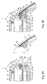
- FIGS 1A and 1B show schematic views in diametral section of a first embodiment of the wristwatch 1 as a portable object before and after the binding of the bracelet 9 to the housing 3 of the watch.
- This wristwatch 1 comprises firstly a housing, which has a side wall 3, such as a middle-bezel, and a bottom 2, and a mirror 16 conventionally attached to the side wall 3 at means of a lining 19 sealing the housing at the level of the ice 16.
- the bottom 2 is fixed to the side wall 3 by snap-fastening, by screwing, by a system with bayonet, or by other means so as to compress a liner 15 which ensures the tightness of the housing at the bottom 2.
- the wristwatch 1 still includes a watch movement, no shown in the housing of the watch 1 to drive needles, no represented, indicating the time, which are placed in front of a dial 17, and a crown or button not shown in particular for setting the time.
- This dial 17 is spaced from the window 16 by a flange 18.
- the dial 17 could to be a liquid crystal display device for displaying, in particular, hourly information provided by a time circuit, not shown, powered by a battery or accumulator 14 placed in the bottom 2 of the housing.
- the wristwatch 1 comprises connection means electrical 4, 8 to electrically connect including at least one conductive track 6 partially integrated into the bracelet 9 to at least one contact terminal 11a of the circuit 11.
- the electronic circuit 11 is disposed on a circuit board printed 10 which is placed between the battery or the accumulator 14, and the dial 17.
- the circuit electronic system is powered by the battery or accumulator for the performance of functions other than watch functions.
- This electronic circuit 11 can include means for transmitting and / or receiving signals radio frequencies in connection with an antenna defined by the conductive track 6 in the bracelet 9, and means for processing the information transmitted or received in said signals.
- connection means consist essentially of a connector electric 4 of cylindrical general shape like a rod or a nail, which is hunted in a suitable opening 12 of the wall 3 of the housing in cooperation with a joint semi-rigid insulating ring 5, which surrounds it.
- a connector electric 4 of cylindrical general shape like a rod or a nail
- a joint semi-rigid insulating ring 5 which surrounds it.
- the annular seal 5 inserted with the connector 4 in the opening 12 is preferably a Hytrel® seal, or possibly an Asutan® seal which is used for fixing the bottom of the case to the middle part.
- the wall and the bottom of the housing can be made of any type of material, for example plastic or metal without influence on the metal connector.
- the through opening 12 of the wall 3 of the housing consists of two coaxial parts of generally cylindrical shape.
- a first part 12b side inside the housing is of diameter less than a second part 12a outside housing.
- a stop is thus defined between the first and second parts 12a and 12b of the opening 12.
- the electrical connector 4 also comprises two coaxial parts of cylindrical shape, such as an outer portion 4a and an inner portion 4b.
- Gasket ring placed on the connector has a shape complementary to the two parts 4a and 4b of the connector 4 and the opening 12. In this way, the connector 4 with the seal ring 5 can be driven into the opening 12 stopping in support against the stop between the first and second portions 12a and 12b of the opening 12.
- the length of the gasket 5 can be of identical size to the length of the opening 12 of the wall 3 of the housing to ensure good insulation.
- the electrical connector 4 comprises an outer portion 4a, and a inner part 4b which each protrude from the wall 3 of the housing.
- the part 4a thus forms a protuberance from the outer surface 23 of the wall 3 of the housing.
- the chamfered end of the inner part 4b of the connector 4 contacts electrically a spring blade 8 exerting a contact force against this blade, which is fixed on the printed circuit board 10.
- This blade spring 8 of electrical connection means is electrically connected to a contact terminal 11a of the electronic circuit 11 via a metal track shown schematically in Figure 2.
- the electrical connector 4 can be made for example of stainless steel (316L) or in a material similar to that used for piano strings.
- This electrical connector in this first embodiment includes a hole 4c blind which extends over most of its length. This one-eyed hole is open towards the outside of the housing with a conical flare at its mouth for facilitate the introduction of a free end 6a of the conductive track 6 of the bracelet 9 which is of complementary shape to said blind hole 4c.
- the conductive track 6 is preferably made of the same material as the electrical connector 4, that is to say in stainless steel (316L) or in a material similar to that used for piano strings.
- the free end 6a of this conductive track 6 can be inserted by force or slightly pinched in said hole 4c as explained below to establish an electrical contact. It can be expected also before mounting the end of the conductive track in the blind hole 4c to deposit in the hole a viscous protective material. This viscous material must be chosen to prevent other materials from lodging and to give additional protection against corrosion of this connector 4 due to environmental constraints.
- a flexible material of at least one strand 9 of the bracelet is overmolded in a flexible material of at least one strand 9 of the bracelet to be integrated in said strand.
- This flexible material can be for example a elastomer, such as polyurethane.
- a hard plastic insert 7 is also overmoulded in the flexible material to the end of the strand 9 to attach to the housing 3 of the watch 1.
- the conductive track 6 completely traverses in this first embodiment the insulating insert 7 for open into a housing 24 of the insert 7.
- the insert is made of plastic hard, such as polyphenylene sulphide (PPS) which can be loaded with glass fibers, it can serve as a guide at the end of the conductive track. In this way, the free end 6a of this conductive track 6 is positioned in one direction insertion into the blind hole 4c of the connector 4 corresponding to the longitudinal axis of the hole 4c.
- PPS polyphenylene sulphide
- a surface 25 of this insert 7 comes in direct contact with the outer surface 23 of the housing while allowing the end 6a free of the conductive track 6 to be introduced in the insertion direction in said blind hole 4c.
- This surface 25 of the insert is for example complementary to the outer surface 23 of the wall 3 which prevents a rotation of the strand of the bracelet to level of the connection of the free end 6a of the conductive track 6 in the hole blind 4c of the connector 4.
- housing 24 of the insert 7 may be partly of complementary shape to the protuberance of the part 4 of the connector 4. This allows this housing 24 to receive this protuberance in order to isolate environmental stresses, the electrical connection of the free end 6a of the conductive track 6 inserted into the blind hole 4c of the connector 4.
- the attachment system to the case of the bracelet which may include one or two strands 9, can be traditionally constituted by two pairs of horns 20 of the wall side 3 of the housing, and by fixing pins passing through each of the passages 21 horns 20 and a passage 22 made partly in the insert 7.
- All the essential elements constituting the wristwatch 1 are represented in a simplified manner in FIG. 2 in a three-dimensional view in a form exploded.
- the printed circuit board 10 on which are mounted in particular the electronic circuit 11 described above and the contact blade 8, which is introduced into the housing 2 and 3.
- a metal track 10a of the printed circuit board 10 electrically connects a contact terminal 11 a of the electronic circuit 11 to the contact blade 8.
- the other terminals of contact of the electronic circuit are connected to other electrical components, not shown, and the battery or accumulator for its power supply.
- This printed circuit board 10 can be mounted in the housing 2 and 3 after having driven the connector 4 with its annular seal 5 in the opening 12 of the wall 3 of the housing. In this way, the contact spring blade 8 flexes in contact with the part inside connector 4.
- the strand 9 of the bracelet can be attached to the housing between the horns 20.
- the surface 25 of the insert is brought into contact with the outer surface 23 of the wall 3 and the free end 6a of the conductive track is thus introduced into the blind hole of the connector 4.
- the end of the strand 9 is attached to the housing with the aid of the metal pin 26 and its protective tube 27, which are inserted into the passages 21 of the horns 20 and in the passage 22 of the insert 7. In this way, the end of the strand is held fixed to the housing without allowing rotation around the pin with the hard plastic insert 7 in direct contact with the wall 3 of the housing. This preserves the free end 6a of the conductive track 6 from any constraint mechanical imposed by the wearer of the watch.
- the wristwatch may comprise more than one connector 4 for the connection of two free ends of the same track conductive or two conductive tracks.
- the conductive track or tracks 6 can be part of the same strand 9 of bracelet or two strands of bracelet.
- the two connectors are fixed through the wall 3 of the housing in positions diametrically opposite.
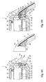
- Figures 3A and 3B show schematic views in diametral section a second embodiment of the wristwatch 1 as a portable object before and after the binding of the bracelet 9 to the housing 3 of the watch. It should be noted that elements of Figures 3A and 3B, corresponding to those of Figures 1A and 1B, identical reference signs. As a result of simplification, it will not be repeated the description of these elements.
- the essential difference of this second form of execution lies in the fact that the electrical connector 4 does not include a blind hole.
- the connection with the free end 6a of the conductive track 6 in the shape of a spring blade is made thanks to the protuberance of the outer portion 4a of the connector.
- This protuberance 4a is positioned outside the wall 3 of the housing. In this way, the protuberance 4a elastically compresses the free end 6a of the track conductive in the housing 24 of the insert 7, when the end of the strand 9 of the bracelet is attached between the horns 20 of the housing.
- Figures 4A and 4B show schematic views of diametrical cut of a third embodiment of the wristwatch 1 as a portable object before and after the binding of the bracelet 9 to the housing 3 of the watch. It is note that the elements of Figures 4A and 4B, which correspond to those figures 1A and 1B, bear identical reference signs. By simplification, he will not be repeated the description of these elements.
- the essential difference of this third embodiment lies in the fact that the electrical connector 4 does not include a blind hole, but only a protuberance 4a outside the wall 3 of the housing.
- the end of the track conductor 6 partially passes through the insert 7 to electrically connect a layer or metal sleeve 13 disposed in the housing 24 of the insert 7.
- This socket metal electrically contacts the protuberance 4a of the form connector complementary to housing with the metal layer, when the end of the strand 9 bracelet is attached between the horns 20 of the housing.
- the conductive track may be a wire or a metal blade whose end is shaped complementary to the blind hole of the connector.
Landscapes
- Physics & Mathematics (AREA)
- General Physics & Mathematics (AREA)
- Electric Clocks (AREA)
Priority Applications (1)
| Application Number | Priority Date | Filing Date | Title |
|---|---|---|---|
| EP20030026428 EP1538697B1 (de) | 2003-11-19 | 2003-11-19 | Tragbares Armbandgerät mit einer elektrischen Verbindungsvorrichtung durch das Gehäuse |
Applications Claiming Priority (1)
| Application Number | Priority Date | Filing Date | Title |
|---|---|---|---|
| EP20030026428 EP1538697B1 (de) | 2003-11-19 | 2003-11-19 | Tragbares Armbandgerät mit einer elektrischen Verbindungsvorrichtung durch das Gehäuse |
Publications (2)
| Publication Number | Publication Date |
|---|---|
| EP1538697A1 true EP1538697A1 (de) | 2005-06-08 |
| EP1538697B1 EP1538697B1 (de) | 2014-04-23 |
Family
ID=34442858
Family Applications (1)
| Application Number | Title | Priority Date | Filing Date |
|---|---|---|---|
| EP20030026428 Expired - Lifetime EP1538697B1 (de) | 2003-11-19 | 2003-11-19 | Tragbares Armbandgerät mit einer elektrischen Verbindungsvorrichtung durch das Gehäuse |
Country Status (1)
| Country | Link |
|---|---|
| EP (1) | EP1538697B1 (de) |
Families Citing this family (3)
| Publication number | Priority date | Publication date | Assignee | Title |
|---|---|---|---|---|
| CN106252877B (zh) * | 2016-07-29 | 2019-03-19 | 惠州Tcl移动通信有限公司 | 一种天线连接结构及具有该天线连接结构的电子设备 |
| CN107077102A (zh) * | 2017-01-16 | 2017-08-18 | 深圳市大疆创新科技有限公司 | 手表及其表带 |
| EP3712719B1 (de) * | 2019-03-20 | 2021-11-10 | Renata AG | Armbanduhr mit in der schliesse integrierter batterie |
Citations (4)
| Publication number | Priority date | Publication date | Assignee | Title |
|---|---|---|---|---|
| DE2553559A1 (de) * | 1975-11-28 | 1977-06-02 | Karl Fischer | Federklemmanschluss zur verbindung zweier elektrischer anschlussteile |
| US4629329A (en) * | 1984-04-26 | 1986-12-16 | Citizen Watch Co., Ltd. | Electronic wristwatch |
| US5742256A (en) * | 1993-05-07 | 1998-04-21 | Seiko Epson Corporation | Wristband having embedded electrically conductive members for a wrist-mountable type electronic device |
| US6239759B1 (en) * | 1998-01-05 | 2001-05-29 | Telefonaktiebolaget Lm Ericsson (Publ) | Antenna connector |
-
2003
- 2003-11-19 EP EP20030026428 patent/EP1538697B1/de not_active Expired - Lifetime
Patent Citations (4)
| Publication number | Priority date | Publication date | Assignee | Title |
|---|---|---|---|---|
| DE2553559A1 (de) * | 1975-11-28 | 1977-06-02 | Karl Fischer | Federklemmanschluss zur verbindung zweier elektrischer anschlussteile |
| US4629329A (en) * | 1984-04-26 | 1986-12-16 | Citizen Watch Co., Ltd. | Electronic wristwatch |
| US5742256A (en) * | 1993-05-07 | 1998-04-21 | Seiko Epson Corporation | Wristband having embedded electrically conductive members for a wrist-mountable type electronic device |
| US6239759B1 (en) * | 1998-01-05 | 2001-05-29 | Telefonaktiebolaget Lm Ericsson (Publ) | Antenna connector |
Also Published As
| Publication number | Publication date |
|---|---|
| EP1538697B1 (de) | 2014-04-23 |
Similar Documents
| Publication | Publication Date | Title |
|---|---|---|
| EP1513221A1 (de) | Tragbares Armbandgerät mit elektrischem Verbindungselement durchs Gehäuse und Verfahren zur Montage des Verbindungselements | |
| EP0766152B1 (de) | Uhr mit einer Antenne | |
| EP1416582B1 (de) | Tragbare elektronische Vorrichtung mit einer elektrischen Verbindung in dem Vorrichtungsgehäuse | |
| EP2741152B1 (de) | Armbanduhr, die mit einem elektrischen Steckverbinder ausgestattet ist | |
| EP2009453B1 (de) | Rogowski-Stromsensor | |
| CH690525A5 (fr) | Pièce d'horlogerie comportant une antenne de réception et/ou de transmission d'un signal radio-diffusé. | |
| EP1143573A1 (de) | Koaxialer Verbinder | |
| EP1513220A1 (de) | Patch-Antenne integriert in einer Armbanduhr | |
| EP1489471A1 (de) | Erdung von einer gedruckten Schaltung eingestellt in einen Armband elektronischen Gerät | |
| EP1274150A1 (de) | Armbanduhr mit Antenne | |
| EP1498044B1 (de) | Verschluss für ein Armband, das mit einer Antenne ausgerüstet ist, und Armband, das diesen Verschluss umfasst | |
| EP0710900A1 (de) | Uhr mit einer in einem metallischen Gehäuse montierten wasserdichten Schale | |
| EP1434114B1 (de) | Uhrengehäuse mit Boden oder Deckel mit Bajonettverschluss der manuell geöffnet werden kann | |
| EP1540427B1 (de) | Uhr mit einem elektronischen modul zum informationspeichern, das im boden angeordnet ist | |
| EP1284335B2 (de) | Türgriff mit Elektronikmodul insbesondere für Kraftfahrzeuge | |
| EP0186804B1 (de) | Am Armgelenk zu tragende elektronische Vorrichtung | |
| EP1519457B1 (de) | Adapter für ein tragbares elektronisches Gerät und Übertragungssystem zwischen diesen Bauteilen | |
| EP1538697B1 (de) | Tragbares Armbandgerät mit einer elektrischen Verbindungsvorrichtung durch das Gehäuse | |
| FR2977936A1 (fr) | Dispositif capteur ou detecteur avec un bouchon guide-cable perfectionne | |
| EP1593317B1 (de) | Armband, insbesondere für eine Uhr, mit einem eingearbeiteten elektrisch leitenden Element | |
| EP0844685B1 (de) | Uhr mit Antenne zum Empfangen und/oder Aussenden von Funksignalen | |
| EP0269872B1 (de) | Uhrengehäuse | |
| EP0954051A1 (de) | Schlitzantenne, insbesondere für eine Uhr | |
| EP1513222B1 (de) | Tragbares Armbandgerät mit elektrischem Verbindungselement durchs Gehäuse und Verfahren zur Montage des Verbindungselements | |
| EP0854539A1 (de) | Elektrische schaltungs vorrichtung |
Legal Events
| Date | Code | Title | Description |
|---|---|---|---|
| PUAI | Public reference made under article 153(3) epc to a published international application that has entered the european phase |
Free format text: ORIGINAL CODE: 0009012 |
|
| AK | Designated contracting states |
Kind code of ref document: A1 Designated state(s): AT BE BG CH CY CZ DE DK EE ES FI FR GB GR HU IE IT LI LU MC NL PT RO SE SI SK TR |
|
| AX | Request for extension of the european patent |
Extension state: AL LT LV MK |
|
| 17P | Request for examination filed |
Effective date: 20051208 |
|
| AKX | Designation fees paid |
Designated state(s): AT BE BG CH CY CZ DE DK EE ES FI FR GB GR HU IE IT LI LU MC NL PT RO SE SI SK TR |
|
| REG | Reference to a national code |
Ref country code: HK Ref legal event code: DE Ref document number: 1079342 Country of ref document: HK |
|
| 17Q | First examination report despatched |
Effective date: 20070531 |
|
| REG | Reference to a national code |
Ref country code: DE Ref legal event code: R079 Ref document number: 60346038 Country of ref document: DE Free format text: PREVIOUS MAIN CLASS: H01Q0001270000 Ipc: G04G0017040000 |
|
| RIC1 | Information provided on ipc code assigned before grant |
Ipc: H01Q 1/27 20060101ALI20131106BHEP Ipc: G04R 60/04 20130101AFI20131106BHEP |
|
| GRAP | Despatch of communication of intention to grant a patent |
Free format text: ORIGINAL CODE: EPIDOSNIGR1 |
|
| RIC1 | Information provided on ipc code assigned before grant |
Ipc: G04R 60/04 20130101ALI20131209BHEP Ipc: G04G 17/04 20060101AFI20131209BHEP Ipc: H01Q 1/27 20060101ALI20131209BHEP |
|
| INTG | Intention to grant announced |
Effective date: 20140102 |
|
| GRAS | Grant fee paid |
Free format text: ORIGINAL CODE: EPIDOSNIGR3 |
|
| GRAA | (expected) grant |
Free format text: ORIGINAL CODE: 0009210 |
|
| AK | Designated contracting states |
Kind code of ref document: B1 Designated state(s): AT BE BG CH CY CZ DE DK EE ES FI FR GB GR HU IE IT LI LU MC NL PT RO SE SI SK TR |
|
| REG | Reference to a national code |
Ref country code: GB Ref legal event code: FG4D Free format text: NOT ENGLISH |
|
| REG | Reference to a national code |
Ref country code: CH Ref legal event code: EP |
|
| REG | Reference to a national code |
Ref country code: AT Ref legal event code: REF Ref document number: 664186 Country of ref document: AT Kind code of ref document: T Effective date: 20140515 Ref country code: CH Ref legal event code: NV Representative=s name: ICB INGENIEURS CONSEILS EN BREVETS SA, CH |
|
| REG | Reference to a national code |
Ref country code: IE Ref legal event code: FG4D Free format text: LANGUAGE OF EP DOCUMENT: FRENCH |
|
| REG | Reference to a national code |
Ref country code: DE Ref legal event code: R096 Ref document number: 60346038 Country of ref document: DE Effective date: 20140605 |
|
| REG | Reference to a national code |
Ref country code: AT Ref legal event code: MK05 Ref document number: 664186 Country of ref document: AT Kind code of ref document: T Effective date: 20140423 |
|
| REG | Reference to a national code |
Ref country code: NL Ref legal event code: VDEP Effective date: 20140423 |
|
| PG25 | Lapsed in a contracting state [announced via postgrant information from national office to epo] |
Ref country code: NL Free format text: LAPSE BECAUSE OF FAILURE TO SUBMIT A TRANSLATION OF THE DESCRIPTION OR TO PAY THE FEE WITHIN THE PRESCRIBED TIME-LIMIT Effective date: 20140423 Ref country code: BG Free format text: LAPSE BECAUSE OF FAILURE TO SUBMIT A TRANSLATION OF THE DESCRIPTION OR TO PAY THE FEE WITHIN THE PRESCRIBED TIME-LIMIT Effective date: 20140723 Ref country code: CY Free format text: LAPSE BECAUSE OF FAILURE TO SUBMIT A TRANSLATION OF THE DESCRIPTION OR TO PAY THE FEE WITHIN THE PRESCRIBED TIME-LIMIT Effective date: 20140423 Ref country code: FI Free format text: LAPSE BECAUSE OF FAILURE TO SUBMIT A TRANSLATION OF THE DESCRIPTION OR TO PAY THE FEE WITHIN THE PRESCRIBED TIME-LIMIT Effective date: 20140423 Ref country code: GR Free format text: LAPSE BECAUSE OF FAILURE TO SUBMIT A TRANSLATION OF THE DESCRIPTION OR TO PAY THE FEE WITHIN THE PRESCRIBED TIME-LIMIT Effective date: 20140724 |
|
| PG25 | Lapsed in a contracting state [announced via postgrant information from national office to epo] |
Ref country code: SE Free format text: LAPSE BECAUSE OF FAILURE TO SUBMIT A TRANSLATION OF THE DESCRIPTION OR TO PAY THE FEE WITHIN THE PRESCRIBED TIME-LIMIT Effective date: 20140423 Ref country code: AT Free format text: LAPSE BECAUSE OF FAILURE TO SUBMIT A TRANSLATION OF THE DESCRIPTION OR TO PAY THE FEE WITHIN THE PRESCRIBED TIME-LIMIT Effective date: 20140423 Ref country code: ES Free format text: LAPSE BECAUSE OF FAILURE TO SUBMIT A TRANSLATION OF THE DESCRIPTION OR TO PAY THE FEE WITHIN THE PRESCRIBED TIME-LIMIT Effective date: 20140423 |
|
| PG25 | Lapsed in a contracting state [announced via postgrant information from national office to epo] |
Ref country code: PT Free format text: LAPSE BECAUSE OF FAILURE TO SUBMIT A TRANSLATION OF THE DESCRIPTION OR TO PAY THE FEE WITHIN THE PRESCRIBED TIME-LIMIT Effective date: 20140825 |
|
| REG | Reference to a national code |
Ref country code: DE Ref legal event code: R097 Ref document number: 60346038 Country of ref document: DE |
|
| PG25 | Lapsed in a contracting state [announced via postgrant information from national office to epo] |
Ref country code: SK Free format text: LAPSE BECAUSE OF FAILURE TO SUBMIT A TRANSLATION OF THE DESCRIPTION OR TO PAY THE FEE WITHIN THE PRESCRIBED TIME-LIMIT Effective date: 20140423 Ref country code: DK Free format text: LAPSE BECAUSE OF FAILURE TO SUBMIT A TRANSLATION OF THE DESCRIPTION OR TO PAY THE FEE WITHIN THE PRESCRIBED TIME-LIMIT Effective date: 20140423 Ref country code: RO Free format text: LAPSE BECAUSE OF FAILURE TO SUBMIT A TRANSLATION OF THE DESCRIPTION OR TO PAY THE FEE WITHIN THE PRESCRIBED TIME-LIMIT Effective date: 20140423 Ref country code: CZ Free format text: LAPSE BECAUSE OF FAILURE TO SUBMIT A TRANSLATION OF THE DESCRIPTION OR TO PAY THE FEE WITHIN THE PRESCRIBED TIME-LIMIT Effective date: 20140423 Ref country code: EE Free format text: LAPSE BECAUSE OF FAILURE TO SUBMIT A TRANSLATION OF THE DESCRIPTION OR TO PAY THE FEE WITHIN THE PRESCRIBED TIME-LIMIT Effective date: 20140423 |
|
| PLBE | No opposition filed within time limit |
Free format text: ORIGINAL CODE: 0009261 |
|
| STAA | Information on the status of an ep patent application or granted ep patent |
Free format text: STATUS: NO OPPOSITION FILED WITHIN TIME LIMIT |
|
| PG25 | Lapsed in a contracting state [announced via postgrant information from national office to epo] |
Ref country code: IT Free format text: LAPSE BECAUSE OF FAILURE TO SUBMIT A TRANSLATION OF THE DESCRIPTION OR TO PAY THE FEE WITHIN THE PRESCRIBED TIME-LIMIT Effective date: 20140423 |
|
| 26N | No opposition filed |
Effective date: 20150126 |
|
| REG | Reference to a national code |
Ref country code: DE Ref legal event code: R097 Ref document number: 60346038 Country of ref document: DE Effective date: 20150126 |
|
| PG25 | Lapsed in a contracting state [announced via postgrant information from national office to epo] |
Ref country code: BE Free format text: LAPSE BECAUSE OF NON-PAYMENT OF DUE FEES Effective date: 20141130 Ref country code: LU Free format text: LAPSE BECAUSE OF FAILURE TO SUBMIT A TRANSLATION OF THE DESCRIPTION OR TO PAY THE FEE WITHIN THE PRESCRIBED TIME-LIMIT Effective date: 20141119 Ref country code: MC Free format text: LAPSE BECAUSE OF FAILURE TO SUBMIT A TRANSLATION OF THE DESCRIPTION OR TO PAY THE FEE WITHIN THE PRESCRIBED TIME-LIMIT Effective date: 20140423 |
|
| GBPC | Gb: european patent ceased through non-payment of renewal fee |
Effective date: 20141119 |
|
| PG25 | Lapsed in a contracting state [announced via postgrant information from national office to epo] |
Ref country code: SI Free format text: LAPSE BECAUSE OF FAILURE TO SUBMIT A TRANSLATION OF THE DESCRIPTION OR TO PAY THE FEE WITHIN THE PRESCRIBED TIME-LIMIT Effective date: 20140423 |
|
| REG | Reference to a national code |
Ref country code: IE Ref legal event code: MM4A |
|
| REG | Reference to a national code |
Ref country code: FR Ref legal event code: PLFP Year of fee payment: 13 |
|
| PG25 | Lapsed in a contracting state [announced via postgrant information from national office to epo] |
Ref country code: IE Free format text: LAPSE BECAUSE OF NON-PAYMENT OF DUE FEES Effective date: 20141119 Ref country code: GB Free format text: LAPSE BECAUSE OF NON-PAYMENT OF DUE FEES Effective date: 20141119 |
|
| PG25 | Lapsed in a contracting state [announced via postgrant information from national office to epo] |
Ref country code: TR Free format text: LAPSE BECAUSE OF FAILURE TO SUBMIT A TRANSLATION OF THE DESCRIPTION OR TO PAY THE FEE WITHIN THE PRESCRIBED TIME-LIMIT Effective date: 20140423 Ref country code: HU Free format text: LAPSE BECAUSE OF FAILURE TO SUBMIT A TRANSLATION OF THE DESCRIPTION OR TO PAY THE FEE WITHIN THE PRESCRIBED TIME-LIMIT; INVALID AB INITIO Effective date: 20031119 |
|
| REG | Reference to a national code |
Ref country code: FR Ref legal event code: PLFP Year of fee payment: 14 |
|
| REG | Reference to a national code |
Ref country code: FR Ref legal event code: PLFP Year of fee payment: 15 |
|
| REG | Reference to a national code |
Ref country code: CH Ref legal event code: PFUS Owner name: THE SWATCH GROUP RESEARCH AND DEVELOPMENT LTD , CH Free format text: FORMER OWNER: ASULAB S.A., CH |
|
| REG | Reference to a national code |
Ref country code: FR Ref legal event code: PLFP Year of fee payment: 16 |
|
| PGFP | Annual fee paid to national office [announced via postgrant information from national office to epo] |
Ref country code: DE Payment date: 20191021 Year of fee payment: 17 |
|
| PGFP | Annual fee paid to national office [announced via postgrant information from national office to epo] |
Ref country code: FR Payment date: 20191022 Year of fee payment: 17 |
|
| REG | Reference to a national code |
Ref country code: DE Ref legal event code: R119 Ref document number: 60346038 Country of ref document: DE |
|
| PG25 | Lapsed in a contracting state [announced via postgrant information from national office to epo] |
Ref country code: FR Free format text: LAPSE BECAUSE OF NON-PAYMENT OF DUE FEES Effective date: 20201130 |
|
| PG25 | Lapsed in a contracting state [announced via postgrant information from national office to epo] |
Ref country code: DE Free format text: LAPSE BECAUSE OF NON-PAYMENT OF DUE FEES Effective date: 20210601 |
|
| PGFP | Annual fee paid to national office [announced via postgrant information from national office to epo] |
Ref country code: CH Payment date: 20221201 Year of fee payment: 20 |
|
| P01 | Opt-out of the competence of the unified patent court (upc) registered |
Effective date: 20230814 |
|
| REG | Reference to a national code |
Ref country code: CH Ref legal event code: PL |