EP1538697A1 - Portable device with bracelet having electrical connecting means through the housing - Google Patents
Portable device with bracelet having electrical connecting means through the housing Download PDFInfo
- Publication number
- EP1538697A1 EP1538697A1 EP03026428A EP03026428A EP1538697A1 EP 1538697 A1 EP1538697 A1 EP 1538697A1 EP 03026428 A EP03026428 A EP 03026428A EP 03026428 A EP03026428 A EP 03026428A EP 1538697 A1 EP1538697 A1 EP 1538697A1
- Authority
- EP
- European Patent Office
- Prior art keywords
- housing
- connector
- wall
- conductive track
- portable object
- Prior art date
- Legal status (The legal status is an assumption and is not a legal conclusion. Google has not performed a legal analysis and makes no representation as to the accuracy of the status listed.)
- Granted
Links
- 239000002184 metal Substances 0.000 claims description 17
- 230000000295 complement effect Effects 0.000 claims description 14
- 230000007613 environmental effect Effects 0.000 claims description 4
- 238000003780 insertion Methods 0.000 claims description 4
- 230000037431 insertion Effects 0.000 claims description 4
- 229910001220 stainless steel Inorganic materials 0.000 claims description 4
- 239000010935 stainless steel Substances 0.000 claims description 4
- 230000001681 protective effect Effects 0.000 claims description 3
- 239000011345 viscous material Substances 0.000 claims description 3
- 230000005540 biological transmission Effects 0.000 claims description 2
- 239000007769 metal material Substances 0.000 claims description 2
- 239000004020 conductor Substances 0.000 abstract description 11
- 239000000463 material Substances 0.000 description 9
- 238000007789 sealing Methods 0.000 description 5
- 239000004033 plastic Substances 0.000 description 4
- 229920003023 plastic Polymers 0.000 description 4
- 238000009413 insulation Methods 0.000 description 2
- 229920000265 Polyparaphenylene Polymers 0.000 description 1
- UCKMPCXJQFINFW-UHFFFAOYSA-N Sulphide Chemical compound [S-2] UCKMPCXJQFINFW-UHFFFAOYSA-N 0.000 description 1
- 230000004308 accommodation Effects 0.000 description 1
- 230000007797 corrosion Effects 0.000 description 1
- 238000005260 corrosion Methods 0.000 description 1
- 230000000694 effects Effects 0.000 description 1
- 229920001971 elastomer Polymers 0.000 description 1
- 239000000806 elastomer Substances 0.000 description 1
- 230000006353 environmental stress Effects 0.000 description 1
- 239000003365 glass fiber Substances 0.000 description 1
- 239000004973 liquid crystal related substance Substances 0.000 description 1
- 238000012423 maintenance Methods 0.000 description 1
- 230000002093 peripheral effect Effects 0.000 description 1
- -1 polyphenylene Polymers 0.000 description 1
- 229920002635 polyurethane Polymers 0.000 description 1
- 239000004814 polyurethane Substances 0.000 description 1
- 230000035882 stress Effects 0.000 description 1
Images


Classifications
-
- H—ELECTRICITY
- H01—ELECTRIC ELEMENTS
- H01Q—ANTENNAS, i.e. RADIO AERIALS
- H01Q1/00—Details of, or arrangements associated with, antennas
- H01Q1/27—Adaptation for use in or on movable bodies
- H01Q1/273—Adaptation for carrying or wearing by persons or animals
-
- G—PHYSICS
- G04—HOROLOGY
- G04G—ELECTRONIC TIME-PIECES
- G04G17/00—Structural details; Housings
- G04G17/02—Component assemblies
- G04G17/04—Mounting of electronic components
-
- G—PHYSICS
- G04—HOROLOGY
- G04R—RADIO-CONTROLLED TIME-PIECES
- G04R60/00—Constructional details
- G04R60/04—Antennas attached to or integrated in watch bracelets
Definitions
- the present invention relates to a portable object with a bracelet provided with means electrical connection through the housing.
- the portable object essentially comprises the housing in which is disposed at least one electronic circuit, an attached bracelet to the housing, and the electrical connection means for electrically connecting at least a conductive track of the bracelet to at least one contact terminal of the circuit electronic.
- the term "means of connection” any conductor or set of conductors to ensure electrical connection between at least one contact terminal of an electronic circuit and at less a conductive track disposed in the bracelet.
- the conductive track can be in the form of a conductive wire or a conductive blade. This conductive track may be an antenna for transmitting and receiving signals or electrically connect an electrical component contained in the bracelet and the circuit electronic in the case.
- the portable object is made in the form a portable electronic instrument in the form of a wristwatch.
- This wristwatch may comprise receiving means and / or radiofrequency signals if the conductive track of the bracelet defines a antenna.
- the electronic circuit for processing electrical signals manages the transmission or reception of information signals by the antenna.
- European Patent No. 0 631 341 describes an electronic instrument of the type wristwatch having an antenna housed in the bracelet and connected to a electronic circuit for processing the signals received by the antenna.
- the circuit electronic processing is arranged inside the housing of the instrument on a printed circuit board.
- Connection pads are provided on a region peripheral of the printed circuit board to allow the establishment of a electrical connection between the electronic signal processing circuit and the connection terminals of the antenna which passes through a side wall of the housing.
- it is intended to employ a spring blade-type connector attached to the printed circuit board for each terminal of the antenna, on which support an electrical conductor connected to one of the terminals of the antenna.
- Each conductor connected to an antenna terminal must pass through the side wall in order to lean on the spring blade to establish the electrical contact.
- An annular seal seal is provided around said conductor in the passageway through the wall lateral.
- a disadvantage of the electronic instrument presented in the European patent No. 0 631 341 is that part of the antenna must pass through a side wall of the housing in order to be directly connected to the printed circuit board. Thereby, sealing at the side wall of the housing, even with the annular seal, is not guaranteed in time and according to the handling of the bracelet.
- US Pat. No. 5,168,281 which describes a device for antenna connection for electronic equipment, such as a wristwatch.
- An antenna end housed in a strand of the bracelet is fixed jointly to a electrical conductor.
- This conductor passes through a side wall of the housing in order to come connect a contact blade of a circuit board carrying a circuit electronic.
- An annular seal is provided around the driver in the passage to through the side wall to ensure a certain tightness of the housing.
- the main purpose of the invention is thus to overcome the disadvantages of the art prior to supplying a portable bracelet object provided with connection means electrical through a side wall of the housing sealingly. sealing connection means in the wall of the housing is provided during a change bracelet or the effects of environmental constraints.
- the invention relates to a portable object cited above which is characterized in that the electrical connection means comprise at least one electrical connection element insulatively and sealingly secured through a housing wall to form an integral part of the housing wall.
- An advantage of the portable object according to the invention is that the element of connection, such as a connector remains insulated and sealed in the wall of the housing. As a result, the bracelet can be easily changed without sealing the housing of the portable object, because the conductive track that it contains is not firmly attached to the connector when the electrical contact is made.
- the connector is preferably of generally cylindrical shape under the shape of a metal nail or rod. It is fixed through a suitable opening of the housing wall with a semi-rigid insulating annular seal, which surrounds the connector. For fixing in the opening of the wall of the housing, the connector with the annular seal are preferably driven into the opening by compressing the seal ring to ensure good support, good sealing and good insulation.
- the opening in the wall of the housing which receives a portion of the connector with the seal, may comprise two parts of generally cylindrical shape.
- a first inner side of the housing is of smaller diameter than a second side part outside the housing.
- the intermediate part of the connector and the seal surrounding the intermediate part of the connector are cylindrical complementary to two cylindrical parts of the opening so as to be driven away on a stop in the opening between the first and second parts.
- the metal connector comprises an open blind hole towards the outside of the housing with a conical flare at the mouth of the hole.
- the hole one-eyed is provided to receive one end of the metallic conductive track of complementary shape to the blind hole. It can be expected to coat the inside of the hole one-eyed with a viscous material to preserve the contact surfaces of the connector.
- the end of the conductive track can be of any shape, but preferably in the form of rod or wire, or in the form of blade.
- the connector and the conductive track are made of metallic material, such as stainless steel.
- an end of at least one flexible strand of the bracelet which is connected to the housing, includes a rigid insulating insert through which the track passes conductive.
- a surface of the insert and / or the end of the bracelet strand next to an outer surface of the wall of the housing comes into contact with the wall of the housing to prevent rotation of the bracelet strand at the connection of the end of the conductive track to the connector.
- an outer portion of the metal connector which is fixed through the wall of the housing, defines a protuberance emerging from the wall of the housing.
- the end of the conductive track in the form of a spring blade can come into contact with the protuberance by flexing when the surface of the insert is in direct contact with the outer surface of the housing wall.
- the insert can understand a housing crossed by the conductive track to receive the part connector forming a protuberance of complementary shape to the housing. This isolates the electrical connection between the end of the track conductive and the connector, environmental constraints. This accommodation could be conductive to directly establish electrical contact with the connector when it is inserted into the housing.
- the conductive track can define an antenna for receiving and / or transmitting radiofrequency signals.
- the electronic circuit in the housing includes means for receiving and / or transmitting signals radio frequencies.
- This electronic circuit is mounted on a printed circuit board, which comprises a contact blade connected to the contact terminal of the electronic circuit. This blade flexes in contact with an inner part of the connector to ensure a good electrical contact.
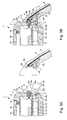
- FIGS 1A and 1B show schematic views in diametral section of a first embodiment of the wristwatch 1 as a portable object before and after the binding of the bracelet 9 to the housing 3 of the watch.
- This wristwatch 1 comprises firstly a housing, which has a side wall 3, such as a middle-bezel, and a bottom 2, and a mirror 16 conventionally attached to the side wall 3 at means of a lining 19 sealing the housing at the level of the ice 16.
- the bottom 2 is fixed to the side wall 3 by snap-fastening, by screwing, by a system with bayonet, or by other means so as to compress a liner 15 which ensures the tightness of the housing at the bottom 2.
- the wristwatch 1 still includes a watch movement, no shown in the housing of the watch 1 to drive needles, no represented, indicating the time, which are placed in front of a dial 17, and a crown or button not shown in particular for setting the time.
- This dial 17 is spaced from the window 16 by a flange 18.
- the dial 17 could to be a liquid crystal display device for displaying, in particular, hourly information provided by a time circuit, not shown, powered by a battery or accumulator 14 placed in the bottom 2 of the housing.
- the wristwatch 1 comprises connection means electrical 4, 8 to electrically connect including at least one conductive track 6 partially integrated into the bracelet 9 to at least one contact terminal 11a of the circuit 11.
- the electronic circuit 11 is disposed on a circuit board printed 10 which is placed between the battery or the accumulator 14, and the dial 17.
- the circuit electronic system is powered by the battery or accumulator for the performance of functions other than watch functions.
- This electronic circuit 11 can include means for transmitting and / or receiving signals radio frequencies in connection with an antenna defined by the conductive track 6 in the bracelet 9, and means for processing the information transmitted or received in said signals.
- connection means consist essentially of a connector electric 4 of cylindrical general shape like a rod or a nail, which is hunted in a suitable opening 12 of the wall 3 of the housing in cooperation with a joint semi-rigid insulating ring 5, which surrounds it.
- a connector electric 4 of cylindrical general shape like a rod or a nail
- a joint semi-rigid insulating ring 5 which surrounds it.
- the annular seal 5 inserted with the connector 4 in the opening 12 is preferably a Hytrel® seal, or possibly an Asutan® seal which is used for fixing the bottom of the case to the middle part.
- the wall and the bottom of the housing can be made of any type of material, for example plastic or metal without influence on the metal connector.
- the through opening 12 of the wall 3 of the housing consists of two coaxial parts of generally cylindrical shape.
- a first part 12b side inside the housing is of diameter less than a second part 12a outside housing.
- a stop is thus defined between the first and second parts 12a and 12b of the opening 12.
- the electrical connector 4 also comprises two coaxial parts of cylindrical shape, such as an outer portion 4a and an inner portion 4b.
- Gasket ring placed on the connector has a shape complementary to the two parts 4a and 4b of the connector 4 and the opening 12. In this way, the connector 4 with the seal ring 5 can be driven into the opening 12 stopping in support against the stop between the first and second portions 12a and 12b of the opening 12.
- the length of the gasket 5 can be of identical size to the length of the opening 12 of the wall 3 of the housing to ensure good insulation.
- the electrical connector 4 comprises an outer portion 4a, and a inner part 4b which each protrude from the wall 3 of the housing.
- the part 4a thus forms a protuberance from the outer surface 23 of the wall 3 of the housing.
- the chamfered end of the inner part 4b of the connector 4 contacts electrically a spring blade 8 exerting a contact force against this blade, which is fixed on the printed circuit board 10.
- This blade spring 8 of electrical connection means is electrically connected to a contact terminal 11a of the electronic circuit 11 via a metal track shown schematically in Figure 2.
- the electrical connector 4 can be made for example of stainless steel (316L) or in a material similar to that used for piano strings.
- This electrical connector in this first embodiment includes a hole 4c blind which extends over most of its length. This one-eyed hole is open towards the outside of the housing with a conical flare at its mouth for facilitate the introduction of a free end 6a of the conductive track 6 of the bracelet 9 which is of complementary shape to said blind hole 4c.
- the conductive track 6 is preferably made of the same material as the electrical connector 4, that is to say in stainless steel (316L) or in a material similar to that used for piano strings.
- the free end 6a of this conductive track 6 can be inserted by force or slightly pinched in said hole 4c as explained below to establish an electrical contact. It can be expected also before mounting the end of the conductive track in the blind hole 4c to deposit in the hole a viscous protective material. This viscous material must be chosen to prevent other materials from lodging and to give additional protection against corrosion of this connector 4 due to environmental constraints.
- a flexible material of at least one strand 9 of the bracelet is overmolded in a flexible material of at least one strand 9 of the bracelet to be integrated in said strand.
- This flexible material can be for example a elastomer, such as polyurethane.
- a hard plastic insert 7 is also overmoulded in the flexible material to the end of the strand 9 to attach to the housing 3 of the watch 1.
- the conductive track 6 completely traverses in this first embodiment the insulating insert 7 for open into a housing 24 of the insert 7.
- the insert is made of plastic hard, such as polyphenylene sulphide (PPS) which can be loaded with glass fibers, it can serve as a guide at the end of the conductive track. In this way, the free end 6a of this conductive track 6 is positioned in one direction insertion into the blind hole 4c of the connector 4 corresponding to the longitudinal axis of the hole 4c.
- PPS polyphenylene sulphide
- a surface 25 of this insert 7 comes in direct contact with the outer surface 23 of the housing while allowing the end 6a free of the conductive track 6 to be introduced in the insertion direction in said blind hole 4c.
- This surface 25 of the insert is for example complementary to the outer surface 23 of the wall 3 which prevents a rotation of the strand of the bracelet to level of the connection of the free end 6a of the conductive track 6 in the hole blind 4c of the connector 4.
- housing 24 of the insert 7 may be partly of complementary shape to the protuberance of the part 4 of the connector 4. This allows this housing 24 to receive this protuberance in order to isolate environmental stresses, the electrical connection of the free end 6a of the conductive track 6 inserted into the blind hole 4c of the connector 4.
- the attachment system to the case of the bracelet which may include one or two strands 9, can be traditionally constituted by two pairs of horns 20 of the wall side 3 of the housing, and by fixing pins passing through each of the passages 21 horns 20 and a passage 22 made partly in the insert 7.
- All the essential elements constituting the wristwatch 1 are represented in a simplified manner in FIG. 2 in a three-dimensional view in a form exploded.
- the printed circuit board 10 on which are mounted in particular the electronic circuit 11 described above and the contact blade 8, which is introduced into the housing 2 and 3.
- a metal track 10a of the printed circuit board 10 electrically connects a contact terminal 11 a of the electronic circuit 11 to the contact blade 8.
- the other terminals of contact of the electronic circuit are connected to other electrical components, not shown, and the battery or accumulator for its power supply.
- This printed circuit board 10 can be mounted in the housing 2 and 3 after having driven the connector 4 with its annular seal 5 in the opening 12 of the wall 3 of the housing. In this way, the contact spring blade 8 flexes in contact with the part inside connector 4.
- the strand 9 of the bracelet can be attached to the housing between the horns 20.
- the surface 25 of the insert is brought into contact with the outer surface 23 of the wall 3 and the free end 6a of the conductive track is thus introduced into the blind hole of the connector 4.
- the end of the strand 9 is attached to the housing with the aid of the metal pin 26 and its protective tube 27, which are inserted into the passages 21 of the horns 20 and in the passage 22 of the insert 7. In this way, the end of the strand is held fixed to the housing without allowing rotation around the pin with the hard plastic insert 7 in direct contact with the wall 3 of the housing. This preserves the free end 6a of the conductive track 6 from any constraint mechanical imposed by the wearer of the watch.
- the wristwatch may comprise more than one connector 4 for the connection of two free ends of the same track conductive or two conductive tracks.
- the conductive track or tracks 6 can be part of the same strand 9 of bracelet or two strands of bracelet.
- the two connectors are fixed through the wall 3 of the housing in positions diametrically opposite.
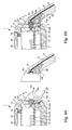
- Figures 3A and 3B show schematic views in diametral section a second embodiment of the wristwatch 1 as a portable object before and after the binding of the bracelet 9 to the housing 3 of the watch. It should be noted that elements of Figures 3A and 3B, corresponding to those of Figures 1A and 1B, identical reference signs. As a result of simplification, it will not be repeated the description of these elements.
- the essential difference of this second form of execution lies in the fact that the electrical connector 4 does not include a blind hole.
- the connection with the free end 6a of the conductive track 6 in the shape of a spring blade is made thanks to the protuberance of the outer portion 4a of the connector.
- This protuberance 4a is positioned outside the wall 3 of the housing. In this way, the protuberance 4a elastically compresses the free end 6a of the track conductive in the housing 24 of the insert 7, when the end of the strand 9 of the bracelet is attached between the horns 20 of the housing.
- Figures 4A and 4B show schematic views of diametrical cut of a third embodiment of the wristwatch 1 as a portable object before and after the binding of the bracelet 9 to the housing 3 of the watch. It is note that the elements of Figures 4A and 4B, which correspond to those figures 1A and 1B, bear identical reference signs. By simplification, he will not be repeated the description of these elements.
- the essential difference of this third embodiment lies in the fact that the electrical connector 4 does not include a blind hole, but only a protuberance 4a outside the wall 3 of the housing.
- the end of the track conductor 6 partially passes through the insert 7 to electrically connect a layer or metal sleeve 13 disposed in the housing 24 of the insert 7.
- This socket metal electrically contacts the protuberance 4a of the form connector complementary to housing with the metal layer, when the end of the strand 9 bracelet is attached between the horns 20 of the housing.
- the conductive track may be a wire or a metal blade whose end is shaped complementary to the blind hole of the connector.
Landscapes
- Physics & Mathematics (AREA)
- General Physics & Mathematics (AREA)
- Electric Clocks (AREA)
Abstract
Description
La présente invention concerne un objet portable à bracelet muni de moyens de connexion électrique à travers le boítier. L'objet portable comprend essentiellement le boítier dans lequel est disposé au moins un circuit électronique, un bracelet attaché au boítier, et les moyens de connexion électrique pour relier électriquement au moins une piste conductrice du bracelet à au moins une borne de contact du circuit électronique.The present invention relates to a portable object with a bracelet provided with means electrical connection through the housing. The portable object essentially comprises the housing in which is disposed at least one electronic circuit, an attached bracelet to the housing, and the electrical connection means for electrically connecting at least a conductive track of the bracelet to at least one contact terminal of the circuit electronic.
Dans la présente description, on entendra par "moyens de connexion électrique" tout conducteur ou ensemble de conducteurs permettant d'assurer une liaison électrique entre au moins une borne de contact d'un circuit électronique et au moins une piste conductrice disposée dans le bracelet. La piste conductrice peut être sous la forme d'un fil conducteur ou d'une lame conductrice. Cette piste conductrice peut être une antenne pour l'émission et la réception de signaux ou permettre de relier électriquement un composant électrique contenu dans le bracelet et le circuit électronique dans le boítier.In the present description, the term "means of connection "any conductor or set of conductors to ensure electrical connection between at least one contact terminal of an electronic circuit and at less a conductive track disposed in the bracelet. The conductive track can be in the form of a conductive wire or a conductive blade. This conductive track may be an antenna for transmitting and receiving signals or electrically connect an electrical component contained in the bracelet and the circuit electronic in the case.
Dans un mode de réalisation préféré, l'objet portable est réalisé sous la forme d'un instrument électronique portable se présentant sous la forme d'une montre-bracelet. Cette montre-bracelet peut comporter des moyens de réception et/ou d'émission de signaux radiofréquences si la piste conductrice du bracelet définit une antenne. Dans ce cas, le circuit électronique de traitement de signaux électriques permet de gérer l'émission ou la réception de signaux d'informations par l'antenne.In a preferred embodiment, the portable object is made in the form a portable electronic instrument in the form of a wristwatch. This wristwatch may comprise receiving means and / or radiofrequency signals if the conductive track of the bracelet defines a antenna. In this case, the electronic circuit for processing electrical signals manages the transmission or reception of information signals by the antenna.
De tels objets portables ont déjà été décrits dans l'art antérieur avec des moyens de connexion électrique entre un circuit électronique disposé dans le boítier des objets et une antenne dans le bracelet.Such portable objects have already been described in the prior art with means for electrical connection between an electronic circuit arranged in the housing objects and an antenna in the bracelet.
Le brevet européen No 0 631 341 décrit un instrument électronique du type montre-bracelet comportant une antenne logée dans le bracelet et connectée à un circuit électronique de traitement des signaux reçus par l'antenne. Le circuit électronique de traitement est disposé à l'intérieur du boítier de l'instrument sur une plaque de circuit imprimé. Des plots de connexion sont ménagés sur une région périphérique de la plaque de circuit imprimé pour permettre l'établissement d'une connexion électrique entre le circuit électronique de traitement des signaux et les bornes de connexion de l'antenne qui traverse une paroi latérale du boítier. Dans une forme de réalisation, il est prévu d'employer un connecteur du type lame ressort fixé à la plaque de circuit imprimé pour chaque borne de l'antenne, sur laquelle vient s'appuyer un conducteur électrique relié à l'une des bornes de l'antenne. Chaque conducteur relié à une borne d'antenne doit traverser la paroi latérale afin de s'appuyer sur la lame ressort pour établir le contact électrique. Un joint annulaire d'étanchéité est prévu autour dudit conducteur dans le passage à travers la paroi latérale.European Patent No. 0 631 341 describes an electronic instrument of the type wristwatch having an antenna housed in the bracelet and connected to a electronic circuit for processing the signals received by the antenna. The circuit electronic processing is arranged inside the housing of the instrument on a printed circuit board. Connection pads are provided on a region peripheral of the printed circuit board to allow the establishment of a electrical connection between the electronic signal processing circuit and the connection terminals of the antenna which passes through a side wall of the housing. In embodiment, it is intended to employ a spring blade-type connector attached to the printed circuit board for each terminal of the antenna, on which support an electrical conductor connected to one of the terminals of the antenna. Each conductor connected to an antenna terminal must pass through the side wall in order to lean on the spring blade to establish the electrical contact. An annular seal seal is provided around said conductor in the passageway through the wall lateral.
Un inconvénient de l'instrument électronique présenté dans le brevet européen No 0 631 341 est qu'une partie de l'antenne doit traverser une paroi latérale du boítier afin de pouvoir être directement connectée sur la plaque de circuit imprimé. De ce fait, l'étanchéité au niveau de la paroi latérale du boítier, même avec le joint annulaire, n'est pas garantie dans le temps et en fonction des manipulations du bracelet.A disadvantage of the electronic instrument presented in the European patent No. 0 631 341 is that part of the antenna must pass through a side wall of the housing in order to be directly connected to the printed circuit board. Thereby, sealing at the side wall of the housing, even with the annular seal, is not guaranteed in time and according to the handling of the bracelet.
Un autre inconvénient de cet instrument électronique est que lors d'un changement de bracelet, chaque conducteur doit être sorti du boítier. De ce fait, l'intérieur du boítier peut être soumis à de la saleté, ce qui nécessite du personnel qualifié pour éviter que le mouvement d'horlogerie ou le circuit garde-temps ne se salisse quand le boítier est ouvert. De plus lors du retrait des conducteurs, les surfaces métalliques de contact entre chaque lame et chaque conducteur peuvent s'oxyder.Another disadvantage of this electronic instrument is that during a bracelet change, each driver must be out of the box. Thereby, the inside of the housing can be subjected to dirt, which requires personnel qualified to prevent the watch movement or the time-keeping circuit from dirty when the case is open. Moreover, during the withdrawal of drivers, metal contact surfaces between each blade and each conductor can oxidize.
On peut citer également le brevet US 5,168,281 qui décrit un dispositif de connexion d'antenne pour un équipement électronique, tel qu'une montre-bracelet. Une extrémité d'antenne logée dans un brin du bracelet est fixée solidairement à un conducteur électrique. Ce conducteur traverse une paroi latérale du boítier afin de venir connecter une lame de contact d'une plaque de circuit imprimé portant un circuit électronique. Un joint annulaire est prévu autour du conducteur dans le passage à travers la paroi latérale pour garantir une certaine étanchéité du boítier.US Pat. No. 5,168,281, which describes a device for antenna connection for electronic equipment, such as a wristwatch. An antenna end housed in a strand of the bracelet is fixed jointly to a electrical conductor. This conductor passes through a side wall of the housing in order to come connect a contact blade of a circuit board carrying a circuit electronic. An annular seal is provided around the driver in the passage to through the side wall to ensure a certain tightness of the housing.
Comme pour le document précédent, un inconvénient de la solution proposée dans le brevet US 5,168,281 est que le conducteur de l'antenne doit traverser une paroi latérale du boítier afin de pouvoir être connecté contre la lame de contact sur la plaque de circuit imprimé. De ce fait, l'étanchéité au niveau de la paroi latérale du boítier, même avec le joint annulaire, n'est pas garantie dans le temps et en fonction des manipulations du bracelet. De plus, lors d'un changement de bracelet, le conducteur avec le joint doit être sorti du boítier ce qui rend difficile ce changement de bracelet et nécessite du personnel qualifié pour éviter de salir l'intérieur du boítier. Par ailleurs, le joint annulaire autour du conducteur doit être également changé lors de multiples retraits d'un même bracelet.As for the previous document, a disadvantage of the proposed solution in US Patent 5,168,281 is that the conductor of the antenna must pass through a side wall of the housing in order to be connected against the contact blade on the printed circuit board. As a result, the seal at the side wall of the housing, even with the ring seal, is not guaranteed in time and in function manipulations of the bracelet. Moreover, during a bracelet change, the driver with the seal must be out of the housing which makes it difficult this change of bracelet and requires qualified personnel to avoid dirtying the inside of the case. By elsewhere, the ring seal around the driver must also be changed when multiple withdrawals of the same bracelet.
L'invention a donc pour but principal de pallier les inconvénients de l'art antérieur en fournissant un objet portable à bracelet muni de moyens de connexion électrique traversant une paroi latérale du boítier de manière étanche. L'étanchéité des moyens de connexion dans la paroi du boítier est assurée lors d'un changement de bracelet ou des effets des contraintes de l'environnement.The main purpose of the invention is thus to overcome the disadvantages of the art prior to supplying a portable bracelet object provided with connection means electrical through a side wall of the housing sealingly. sealing connection means in the wall of the housing is provided during a change bracelet or the effects of environmental constraints.
A cet effet l'invention concerne un objet portable cité ci-devant qui se caractérise en ce que les moyens de connexion électrique comprennent au moins un élément de connexion électrique fixé de manière isolante et étanche à travers une paroi du boítier afin de faire partie intégrante de la paroi du boítier.For this purpose the invention relates to a portable object cited above which is characterized in that the electrical connection means comprise at least one electrical connection element insulatively and sealingly secured through a housing wall to form an integral part of the housing wall.
Un avantage de l'objet portable selon l'invention est que l'élément de connexion, tel qu'un connecteur reste fixé de manière isolante et étanche dans la paroi du boítier. De ce fait, le bracelet peut être aisément changé sans nuire à l'étanchéité du boítier de l'objet portable, car la piste conductrice qu'il contient n'est pas fixée solidairement au connecteur lors de l'établissement du contact électrique.An advantage of the portable object according to the invention is that the element of connection, such as a connector remains insulated and sealed in the wall of the housing. As a result, the bracelet can be easily changed without sealing the housing of the portable object, because the conductive track that it contains is not firmly attached to the connector when the electrical contact is made.
Le connecteur est préférentiellement de forme générale cylindrique sous la forme d'un clou ou d'une tige métallique. Il est fixé à travers une ouverture adaptée de la paroi du boítier avec un joint annulaire isolant semi-rigide, qui entoure le connecteur. Pour la fixation dans l'ouverture de la paroi du boítier, le connecteur avec le joint annulaire sont de préférence chassés dans l'ouverture en comprimant le joint annulaire pour assurer un bon maintien, une bonne étanchéité et une bonne isolation.The connector is preferably of generally cylindrical shape under the shape of a metal nail or rod. It is fixed through a suitable opening of the housing wall with a semi-rigid insulating annular seal, which surrounds the connector. For fixing in the opening of the wall of the housing, the connector with the annular seal are preferably driven into the opening by compressing the seal ring to ensure good support, good sealing and good insulation.
L'ouverture dans la paroi du boítier, qui reçoit une partie du connecteur avec le joint, peut comprendre deux parties de forme généralement cylindrique. Une première partie côté intérieur du boítier est de diamètre inférieur à une seconde partie côté extérieur du boítier. Ainsi, la partie intermédiaire du connecteur et le joint entourant la partie intermédiaire du connecteur sont de forme cylindrique complémentaire aux deux parties cylindriques de l'ouverture de manière à être chassés en prenant appui sur une butée dans l'ouverture entre les première et seconde parties.The opening in the wall of the housing, which receives a portion of the connector with the seal, may comprise two parts of generally cylindrical shape. A first inner side of the housing is of smaller diameter than a second side part outside the housing. Thus, the intermediate part of the connector and the seal surrounding the intermediate part of the connector are cylindrical complementary to two cylindrical parts of the opening so as to be driven away on a stop in the opening between the first and second parts.
Avantageusement, le connecteur métallique comprend un trou borgne ouvert vers l'extérieur du boítier avec un évasement conique à l'embouchure du trou. Le trou borgne est prévu pour recevoir une extrémité de la piste conductrice métallique de forme complémentaire au trou borgne. Il peut être prévu d'enduire l'intérieur du trou borgne avec un matériau visqueux pour préserver les surfaces de contact du connecteur. L'extrémité de la piste conductrice peut être de n'importe quelle forme, mais de préférence sous la forme de tige ou fil, ou sous la forme de lame. De préférence, le connecteur et la piste conductrice sont réalisés en matériau métallique, tel qu'en acier inoxydable.Advantageously, the metal connector comprises an open blind hole towards the outside of the housing with a conical flare at the mouth of the hole. The hole one-eyed is provided to receive one end of the metallic conductive track of complementary shape to the blind hole. It can be expected to coat the inside of the hole one-eyed with a viscous material to preserve the contact surfaces of the connector. The end of the conductive track can be of any shape, but preferably in the form of rod or wire, or in the form of blade. Of preferably, the connector and the conductive track are made of metallic material, such as stainless steel.
Avantageusement, une extrémité d'au moins un brin souple du bracelet, qui est reliée au boítier, comprend un insert rigide isolant à travers lequel passe la piste conductrice. Une surface de l'insert et/ou de l'extrémité du brin de bracelet en regard d'une surface extérieure de la paroi du boítier vient en contact de la paroi du boítier pour empêcher une rotation du brin du bracelet au niveau de la connexion de l'extrémité de la piste conductrice au connecteur.Advantageously, an end of at least one flexible strand of the bracelet, which is connected to the housing, includes a rigid insulating insert through which the track passes conductive. A surface of the insert and / or the end of the bracelet strand next to an outer surface of the wall of the housing comes into contact with the wall of the housing to prevent rotation of the bracelet strand at the connection of the end of the conductive track to the connector.
Avantageusement, une partie extérieure du connecteur métallique, qui est fixé à travers la paroi du boítier, définit une protubérance émergeant de la paroi du boítier. De cette façon, l'extrémité de la piste conductrice sous forme d'une lame ressort peut venir en contact avec la protubérance en fléchissant quand la surface de l'insert est en contact direct avec la surface extérieure de la paroi du boítier. L'insert peut comprendre un logement traversé par la piste conductrice pour recevoir la partie extérieure du connecteur formant une protubérance de forme complémentaire au logement. Ceci permet d'isoler la connexion électrique entre l'extrémité de la piste conductrice et le connecteur, des contraintes de l'environnement. Ce logement pourrait être conducteur pour établir directement le contact électrique avec le connecteur quand ce dernier est introduit dans le logement.Advantageously, an outer portion of the metal connector, which is fixed through the wall of the housing, defines a protuberance emerging from the wall of the housing. In this way, the end of the conductive track in the form of a spring blade can come into contact with the protuberance by flexing when the surface of the insert is in direct contact with the outer surface of the housing wall. The insert can understand a housing crossed by the conductive track to receive the part connector forming a protuberance of complementary shape to the housing. This isolates the electrical connection between the end of the track conductive and the connector, environmental constraints. This accommodation could be conductive to directly establish electrical contact with the connector when it is inserted into the housing.
La piste conductrice peut définir une antenne pour la réception et/ou l'émission de signaux radiofréquences. Dans ce cas, le circuit électronique dans le boítier comprend des moyens pour la réception et/ou l'émission des signaux radiofréquences. Ce circuit électronique est monté sur une plaque de circuit imprimé, qui comprend une lame de contact reliée à la borne de contact du circuit électronique. Cette lame fléchit au contact d'une partie intérieure du connecteur pour assurer un bon contact électrique.The conductive track can define an antenna for receiving and / or transmitting radiofrequency signals. In this case, the electronic circuit in the housing includes means for receiving and / or transmitting signals radio frequencies. This electronic circuit is mounted on a printed circuit board, which comprises a contact blade connected to the contact terminal of the electronic circuit. This blade flexes in contact with an inner part of the connector to ensure a good electrical contact.
Les buts, avantages et caractéristiques de l'objet portable à bracelet apparaítront mieux dans la description suivante de plusieurs formes d'exécution de l'invention en liaison avec les dessins dans lesquels :
- les figures 1A et 1B représentent des vues schématiques en coupe diamétrale partielle d'une première forme d'exécution de l'objet portable avant et après la liaison du bracelet au boítier de l'objet portable selon l'invention,
- la figure 2 représente un vue tridimensionnelle simplifiée en éclaté de la première forme d'exécution d'une partie de l'objet portable selon l'invention,
- les figures 3A et 3B représentent des vues schématiques en coupe diamétrale partielle d'une seconde forme d'exécution de l'objet portable avant et après la liaison du bracelet au boítier de l'objet portable selon l'invention, et
- les figures 4A et 4B représentent des vues schématiques en coupe diamétrale partielle d'une troisième forme d'exécution de l'objet portable avant et après la liaison du bracelet au boítier de l'objet portable selon l'invention.
- FIGS. 1A and 1B show diagrammatic views in partial diametrical section of a first embodiment of the portable object before and after the binding of the bracelet to the housing of the portable object according to the invention,
- FIG. 2 represents a simplified three-dimensional exploded view of the first embodiment of a part of the portable object according to the invention,
- FIGS. 3A and 3B show diagrammatic views in partial diametrical section of a second embodiment of the portable object before and after the binding of the bracelet to the housing of the portable object according to the invention, and
- FIGS. 4A and 4B show diagrammatic views in partial diametrical section of a third embodiment of the portable object before and after the binding of the bracelet to the housing of the portable object according to the invention.
Dans la description suivante, tous les éléments de l'objet portable qui sont bien connus d'un homme du métier dans ce domaine technique, ne seront pas expliqués en détail. Les formes d'exécution décrites concernent spécifiquement un objet portable à titre d'exemple non limitatif sous forme d'une montre-bracelet qui présente des fonctionnalités de réception ou d'émission d'ondes radiofréquences. Il est à noter que tous les mêmes éléments de la montre-bracelet décrits ci-après dans les figures 1 à 4 portent des signes de référence identiques. De ce fait par simplification, il ne sera pas répété la description de chaque élément pour toutes les figures.In the following description, all the elements of the portable object that are well known to a person skilled in this technical field, will not be explained in detail. The execution forms described relate specifically to an object portable as a non-limiting example in the form of a wristwatch which presents radio frequency reception or emission functions. Note that all the same elements of the wristwatch described hereinafter in the figures 1 to 4 carry identical reference signs. For the sake of simplification, it does not will not be repeated the description of each element for all figures.
Les figures 1A et 1 B représentent des vues schématiques en coupe diamétrale
d'une première forme d'exécution de la montre-bracelet 1 en tant qu'objet portable
avant et après la liaison du bracelet 9 au boítier 3 de la montre. Cette montre-bracelet
1 comprend tout d'abord un boítier, qui a une paroi latérale 3, telle qu'une carrure-lunette,
et un fond 2, et une glace 16 fixée classiquement sur la paroi latérale 3 au
moyen d'une garniture 19 assurant l'étanchéité du boítier au niveau de la glace 16. Le
fond 2 est fixé à la paroi latérale 3 par encliquetage, par vissage, par un système à
baïonnette, ou par un autre moyen de façon à comprimer une garniture 15 qui assure
l'étanchéité du boítier au niveau de ce fond 2.Figures 1A and 1B show schematic views in diametral section
of a first embodiment of the
La montre-bracelet 1 comprend encore un mouvement d'horlogerie, non
représenté, dans le boítier de la montre 1 pour entraíner des aiguilles, non
représentées, d'indication de l'heure, qui sont placées devant un cadran 17, et une
couronne ou bouton non représenté notamment pour le réglage de l'heure. Ce cadran
17 est espacé de la glace 16 par un réhaut 18. Bien entendu, le cadran 17 pourrait
être un dispositif d'affichage à cristaux liquides pour afficher notamment des
informations horaires fournies par un circuit garde-temps, non représenté, alimenté
par une pile ou un accumulateur 14 placé dans le fond 2 du boítier.The
Selon l'invention, la montre-bracelet 1 comprend des moyens de connexion
électrique 4, 8 pour relier électriquement notamment au moins une piste conductrice 6
intégrée en partie dans le bracelet 9 à au moins une borne de contact 11a du circuit
électronique 11. Le circuit électronique 11 est disposé sur une plaque de circuit
imprimé 10 qui est placée entre la pile ou l'accumulateur 14, et le cadran 17. Le circuit
électronique est notamment alimenté par la pile ou l'accumulateur pour l'exécution de
fonctions autres que des fonctions horlogères. Ce circuit électronique 11 peut
comprendre notamment des moyens pour l'émission et/ou la réception de signaux
radiofréquences en connexion avec une antenne définie par la piste conductrice 6
dans le bracelet 9, ainsi que des moyens de traitement de l'information émise ou
reçue dans lesdits signaux.According to the invention, the
Les moyens de connexion sont constitués essentiellement par un connecteur
électrique 4 de forme générale cylindrique comme une tige ou un clou, qui est chassé
dans une ouverture adaptée 12 de la paroi 3 du boítier en coopération avec un joint
annulaire isolant semi-rigide 5, qui l'entoure. Pour assurer un bon maintien de
l'ensemble constitué par le connecteur avec son joint isolant annulaire dans
l'ouverture de la paroi 3 du boítier, il est bien entendu nécessaire que le joint soit
dimensionné pour être comprimé lors de son introduction dans ladite ouverture 12.
Grâce à cet assemblage dans l'ouverture 12 à travers la paroi 3 du boítier, le
connecteur électrique 4 est ainsi fixé de manière isolante et étanche afin de faire
partie intégrante de la paroi 3 du boítier.The connection means consist essentially of a
Le joint annulaire 5 inséré avec le connecteur 4 dans l'ouverture 12 est de
préférence un joint Hytrel® , ou éventuellement un joint Asutan® qui est utilisé pour la
fixation du fond du boítier à la carrure. Avec un tel joint isolant, la paroi et le fond du
boítier peuvent être réalisés en tout type de matériau, par exemple en plastique ou en
métal sans influence sur le connecteur métallique.The
L'ouverture traversante 12 de la paroi 3 du boítier est constituée de deux
parties coaxiales de forme généralement cylindrique. Une première partie 12b côté
intérieur du boítier est de diamètre inférieur à une seconde partie 12a côté extérieur
du boítier. Une butée est ainsi définie entre les première et seconde parties 12a et
12b de l'ouverture 12.The through
Le connecteur électrique 4 comprend également deux parties coaxiales de
forme cylindrique, telles qu'une partie extérieure 4a et une partie intérieure 4b. Le joint
annulaire placé sur le connecteur a une forme complémentaire aux deux parties 4a et
4b du connecteur 4 et de l'ouverture 12. De cette façon, le connecteur 4 avec le joint
annulaire 5 peuvent être chassés dans l'ouverture 12 en s'arrêtant en appui contre la
butée entre les première et seconde parties 12a et 12b de l'ouverture 12.The
Il est à noter que la longueur du joint 5 peut être de dimension identique à la
longueur de l'ouverture 12 de la paroi 3 du boítier pour assurer une bonne isolation.
Par contre, le connecteur électrique 4 comprend une partie extérieure 4a, ainsi qu'une
partie intérieure 4b qui dépassent chacune de la paroi 3 du boítier. La partie
extérieure 4a forme ainsi une protubérance depuis la surface extérieure 23 de la paroi
3 du boítier.It should be noted that the length of the
L'extrémité chanfreinée de la partie intérieure 4b du connecteur 4 contacte
électriquement une lame ressort 8 en exerçant une force de contact contre cette
lame, qui est fixée sur la plaque de circuit imprimé 10. Cette lame ressort 8 des
moyens de connexion électrique est reliée électriquement à une borne de contact 11a
du circuit électronique 11 par l'intermédiaire d'une piste métallique montrée
schématiquement à la figure 2.The chamfered end of the
Le connecteur électrique 4 peut être réalisé par exemple en acier inoxydable
(316L) ou dans un matériau similaire à celui utilisé pour des cordes de piano. Ce
connecteur électrique dans cette première forme d'exécution comprend un trou
borgne 4c qui s'étend sur une majeure partie de sa longueur. Ce trou borgne est
ouvert vers l'extérieur du boítier avec un évasement conique à son embouchure pour
faciliter l'introduction d'une extrémité libre 6a de la piste conductrice 6 du bracelet 9
qui est de forme complémentaire audit trou borgne 4c.The
La piste conductrice 6 est réalisée de préférence avec un même matériau que
le connecteur électrique 4, c'est-à-dire en acier inox (316L) ou en un matériau
similaire à celui utilisé pour des cordes de piano. Ainsi, l'extrémité libre 6a de cette
piste conductrice 6 peut être insérée à force ou légèrement pincée dans ledit trou 4c
comme expliqué ci-dessous pour établir un contact électrique. Il peut être prévu
également avant le montage de l'extrémité de la piste conductrice dans le trou borgne
4c de déposer dans le trou un matériau visqueux de protection. Ce matériau visqueux
doit être choisi afin d'empêcher d'autres matériaux de s'y loger et de donner une
protection supplémentaire contre toute corrosion de ce connecteur 4 due aux
contraintes de l'environnement.The
La majeure partie de la piste conductrice 6, sous forme de fil ou de lame
métallique, est surmoulée dans un matériau souple d'au moins un brin 9 du bracelet
afin d'être intégrée dans ledit brin. Ce matériau souple peut être par exemple un
élastomère, tel que du polyuréthane.Most of the
Un insert 7 en plastique dur est également surmoulé dans le matériau souple à
l'extrémité du brin 9 à attacher au boítier 3 de la montre 1. La piste conductrice 6
traverse complètement dans cette première forme d'exécution l'insert isolant 7 pour
déboucher dans un logement 24 de l'insert 7. Comme l'insert est réalisé en plastique
dur, tel qu'en sulfure de poly-phénylène (PPS) qui peut être chargé en fibres de verre,
il peut servir de guide à l'extrémité de la piste conductrice. De cette manière,
l'extrémité libre 6a de cette piste conductrice 6 est positionnée dans une direction
d'insertion dans le trou borgne 4c du connecteur 4 correspondant à l'axe longitudinal
du trou 4c.A
Quand le bracelet est attaché au boítier, une surface 25 de cet insert 7 vient
en contact direct de la surface extérieure 23 du boítier tout en permettant à l'extrémité
libre 6a de la piste conductrice 6 d'être introduite dans la direction d'insertion dans
ledit trou borgne 4c. Cette surface 25 de l'insert est par exemple complémentaire à la
surface extérieure 23 de la paroi 3 ce qui empêche une rotation du brin du bracelet au
niveau de la connexion de l'extrémité libre 6a de la piste conductrice 6 dans le trou
borgne 4c du connecteur 4. Ainsi, cette extrémité libre 6a est préservée de toute
contrainte mécanique imposée par le porteur de la montre. De plus, le logement 24 de
l'insert 7 peut être en partie de forme complémentaire à la protubérance de la partie
extérieure 4a du connecteur 4. Ceci permet à ce logement 24 de recevoir cette
protubérance afin d'isoler des contraintes de l'environnement, la connexion électrique
de l'extrémité libre 6a de la piste conductrice 6 insérée dans le trou borgne 4c du
connecteur 4.When the bracelet is attached to the housing, a
Le système d'attache au boítier du bracelet, qui peut comprendre un ou deux
brins 9, peut être constitué traditionnellement par deux paires de cornes 20 de la paroi
latérale 3 du boítier, et par des goupilles de fixation traversant chacune des passages
21 des cornes 20 et un passage 22 pratiqué en partie dans l'insert 7.The attachment system to the case of the bracelet, which may include one or two
Tous les éléments essentiels constituant la montre-bracelet 1 sont représentés
de manière simplifiée à la figure 2 dans une vue tridimensionnelle sous une forme
éclatée. On remarque sur cette figure 2 tout d'abord la plaque de circuit imprimé 10,
sur laquelle sont montés notamment le circuit électronique 11 décrit ci-dessus et la
lame de contact 8, qui est introduit dans le boítier 2 et 3. Une piste métallique 10a de
la plaque de circuit imprimé 10 relie électriquement une borne de contact 11 a du
circuit électronique 11 à la lame de contact 8. Bien entendu les autres bornes de
contact du circuit électronique sont connectées à d'autres composants électriques,
non représentés, ainsi qu'à la pile ou l'accumulateur pour son alimentation électrique.
Cette plaque de circuit imprimé 10 peut être montée dans le boítier 2 et 3 après avoir
chassé le connecteur 4 avec son joint annulaire 5 dans l'ouverture 12 de la paroi 3 du
boítier. De cette façon, la lame ressort de contact 8 fléchit au contact de la partie
intérieure du connecteur 4.All the essential elements constituting the
Une fois que le connecteur avec le joint sont fixés à travers l'ouverture 12 de la
paroi 3 du boítier, le brin 9 du bracelet peut être attaché au boítier entre les cornes 20.
Pour ce faire, la surface 25 de l'insert est amenée en contact de la surface extérieure
23 de la paroi 3 et l'extrémité libre 6a de la piste conductrice est ainsi introduite dans
le trou borgne du connecteur 4. L'extrémité du brin 9 est attaché au boítier à l'aide de
la goupille métallique 26 et de son tube de protection 27, qui sont insérés dans les
passages 21 des cornes 20 et dans le passage 22 de l'insert 7. De cette façon,
l'extrémité du brin est maintenue fixe au boítier sans permettre une rotation autour de
la goupille grâce à l'insert en plastique dur 7 en contact direct avec la paroi 3 du
boítier. Ceci préserve l'extrémité libre 6a de la piste conductrice 6 de toute contrainte
mécanique imposée par le porteur de la montre.Once the connector with the gasket are attached through the
Bien entendu, la montre-bracelet peut comprendre plus d'un connecteur
électrique 4 pour la connexion de deux extrémités libres d'une même piste
conductrice ou de deux pistes conductrices. La ou les pistes conductrices 6 peuvent
faire partie d'un même brin 9 de bracelet ou de deux brins de bracelet. Dans ce cas,
les deux connecteurs sont fixés à travers la paroi 3 du boítier dans des positions
diamétralement opposée. Of course, the wristwatch may comprise more than one
Les figures 3A et 3B représentent des vues schématiques en coupe diamétrale
d'une seconde forme d'exécution de la montre-bracelet 1 en tant qu'objet portable
avant et après la liaison du bracelet 9 au boítier 3 de la montre. Il est à noter que les
éléments des figures 3A et 3B, qui correspondent à ceux des figures 1A et 1 B, portent
des signes de référence identiques. De ce fait par simplification, il ne sera pas répété
la description de ces éléments.Figures 3A and 3B show schematic views in diametral section
a second embodiment of the
La différence essentielle de cette seconde forme d'exécution réside dans le fait
que le connecteur électrique 4 ne comprend pas de trou borgne. La connexion
électrique avec l'extrémité libre 6a de la piste conductrice 6 en forme de lame ressort
est fait grâce à la protubérance de la partie extérieure 4a du connecteur. Cette
protubérance 4a est positionnée à l'extérieur de la paroi 3 du boítier. De cette façon,
la protubérance 4a vient comprimer élastiquement l'extrémité libre 6a de la piste
conductrice dans le logement 24 de l'insert 7, quand l'extrémité du brin 9 de bracelet
est attaché entre les cornes 20 du boítier.The essential difference of this second form of execution lies in the fact
that the
Finalement, les figures 4A et 4B représentent des vues schématiques en
coupe diamétrale d'une troisième forme d'exécution de la montre-bracelet 1 en tant
qu'objet portable avant et après la liaison du bracelet 9 au boítier 3 de la montre. Il est
à noter que les éléments des figures 4A et 4B, qui correspondent à ceux des figures
1A et 1B, portent des signes de référence identiques. De ce fait par simplification, il
ne sera pas répété la description de ces éléments.Finally, Figures 4A and 4B show schematic views of
diametrical cut of a third embodiment of the
La différence essentielle de cette troisième forme d'exécution réside dans le
fait que le connecteur électrique 4 ne comprend pas de trou borgne, mais uniquement
une protubérance 4a extérieure à la paroi 3 du boítier. L'extrémité de la piste
conductrice 6 traverse en partie l'insert 7 pour connecter électriquement une couche
ou douille métallique 13 disposée dans le logement 24 de l'insert 7. Cette douille
métallique contacte électriquement la protubérance 4a du connecteur de forme
complémentaire au logement avec la couche métallique, quand l'extrémité du brin 9
de bracelet est attachée entre les cornes 20 du boítier.The essential difference of this third embodiment lies in the
fact that the
Grâce au connecteur électrique fixé à travers la paroi du boítier pour faire partie intégrante de ladite paroi, un éventuel remplacement du bracelet est facile à réaliser sans nuire à l'étanchéité du boítier fermé.Thanks to the electrical connector fixed through the wall of the housing to make integral part of said wall, a possible replacement of the bracelet is easy to achieve without compromising the tightness of the closed housing.
A partir de la description qui vient d'être faite de multiples variantes de réalisation de l'objet portable à bracelet peuvent être conçues par l'homme du métier sans sortir du cadre de l'invention définie par les revendications. La piste conductrice peut être un fil métallique ou une lame métallique dont l'extrémité est de forme complémentaire au trou borgne du connecteur.From the description that has just been made of multiple variants of realization of the portable bracelet object can be designed by those skilled in the art without departing from the scope of the invention defined by the claims. The conductive track may be a wire or a metal blade whose end is shaped complementary to the blind hole of the connector.
Claims (15)
Priority Applications (1)
| Application Number | Priority Date | Filing Date | Title |
|---|---|---|---|
| EP20030026428 EP1538697B1 (en) | 2003-11-19 | 2003-11-19 | Portable device with bracelet having electrical connecting means through the housing |
Applications Claiming Priority (1)
| Application Number | Priority Date | Filing Date | Title |
|---|---|---|---|
| EP20030026428 EP1538697B1 (en) | 2003-11-19 | 2003-11-19 | Portable device with bracelet having electrical connecting means through the housing |
Publications (2)
| Publication Number | Publication Date |
|---|---|
| EP1538697A1 true EP1538697A1 (en) | 2005-06-08 |
| EP1538697B1 EP1538697B1 (en) | 2014-04-23 |
Family
ID=34442858
Family Applications (1)
| Application Number | Title | Priority Date | Filing Date |
|---|---|---|---|
| EP20030026428 Expired - Lifetime EP1538697B1 (en) | 2003-11-19 | 2003-11-19 | Portable device with bracelet having electrical connecting means through the housing |
Country Status (1)
| Country | Link |
|---|---|
| EP (1) | EP1538697B1 (en) |
Families Citing this family (3)
| Publication number | Priority date | Publication date | Assignee | Title |
|---|---|---|---|---|
| CN106252877B (en) * | 2016-07-29 | 2019-03-19 | 惠州Tcl移动通信有限公司 | A kind of antenna attachment structure and the electronic equipment with the antenna attachment structure |
| CN107077102A (en) * | 2017-01-16 | 2017-08-18 | 深圳市大疆创新科技有限公司 | Wrist-watch and its watchband |
| EP3712719B1 (en) | 2019-03-20 | 2021-11-10 | Renata AG | A wristwatch with battery integrated in the clasp |
Citations (4)
| Publication number | Priority date | Publication date | Assignee | Title |
|---|---|---|---|---|
| DE2553559A1 (en) * | 1975-11-28 | 1977-06-02 | Karl Fischer | Spring loaded clamp connector for strips - has hook:shaped clamping spring with S:shaped clamping arm and held in insulating block |
| US4629329A (en) * | 1984-04-26 | 1986-12-16 | Citizen Watch Co., Ltd. | Electronic wristwatch |
| US5742256A (en) * | 1993-05-07 | 1998-04-21 | Seiko Epson Corporation | Wristband having embedded electrically conductive members for a wrist-mountable type electronic device |
| US6239759B1 (en) * | 1998-01-05 | 2001-05-29 | Telefonaktiebolaget Lm Ericsson (Publ) | Antenna connector |
-
2003
- 2003-11-19 EP EP20030026428 patent/EP1538697B1/en not_active Expired - Lifetime
Patent Citations (4)
| Publication number | Priority date | Publication date | Assignee | Title |
|---|---|---|---|---|
| DE2553559A1 (en) * | 1975-11-28 | 1977-06-02 | Karl Fischer | Spring loaded clamp connector for strips - has hook:shaped clamping spring with S:shaped clamping arm and held in insulating block |
| US4629329A (en) * | 1984-04-26 | 1986-12-16 | Citizen Watch Co., Ltd. | Electronic wristwatch |
| US5742256A (en) * | 1993-05-07 | 1998-04-21 | Seiko Epson Corporation | Wristband having embedded electrically conductive members for a wrist-mountable type electronic device |
| US6239759B1 (en) * | 1998-01-05 | 2001-05-29 | Telefonaktiebolaget Lm Ericsson (Publ) | Antenna connector |
Also Published As
| Publication number | Publication date |
|---|---|
| EP1538697B1 (en) | 2014-04-23 |
Similar Documents
| Publication | Publication Date | Title |
|---|---|---|
| EP1513221A1 (en) | Portable object with bracelet and electrical connecting flange penetrating the casing, and method of mounting the flange | |
| EP0766152B1 (en) | Timepiece provided with an antenna | |
| EP1416582B1 (en) | Portable electronic device with an electric connection inside the device case | |
| EP2741152B1 (en) | Wristwatch provided with an electrical connector | |
| EP2009453B1 (en) | Rogowski current sensor | |
| CH690525A5 (en) | Timepiece including a receiving antenna and / or transmitting a radio broadcast signal. | |
| EP1143573A1 (en) | Coaxial connector | |
| EP1513220A1 (en) | Patch antenna integrated in a wrist-watch | |
| EP0464767A1 (en) | Device composed of two elements jointed on a hinge and electrically connected | |
| EP1489471A1 (en) | Ground connection of a printed circuit board placed in a wristwatch-type electronic device | |
| EP1540427B1 (en) | Watch comprising an electronic information-storage unit in the base of the case thereof | |
| CH714110A1 (en) | Watch case with moving horns. | |
| EP0186804B1 (en) | Wrist-mounted electronic device | |
| EP1519457B1 (en) | Adaptor for a portable electronic device and transmission system between these elements | |
| EP1538697B1 (en) | Portable device with bracelet having electrical connecting means through the housing | |
| EP1213629A1 (en) | Portable object, in particular time piece, containing a waterproof container mounted within metal case | |
| EP1593317B1 (en) | Bracelet, in particular for a watch, incorporating an electrically conductive element | |
| EP0844685B1 (en) | Timepiece provided with an antenna for receiving and/or transmitting radio signals | |
| EP0954051A1 (en) | Slot antenna in particular for a timepiece | |
| EP1513222B1 (en) | Portable object with bracelet and electrical connecting flange penetrating the casing, and method of mounting the flange | |
| EP0854539A1 (en) | Electrical connections device | |
| WO2015165803A2 (en) | Closure/opening system for a wristlet performing an electrical function | |
| EP0269872A1 (en) | Watch case | |
| FR2766299A3 (en) | Detector assembly method | |
| EP1318437A1 (en) | Watch with transponder that is, at least partially, located in a control member |
Legal Events
| Date | Code | Title | Description |
|---|---|---|---|
| PUAI | Public reference made under article 153(3) epc to a published international application that has entered the european phase |
Free format text: ORIGINAL CODE: 0009012 |
|
| AK | Designated contracting states |
Kind code of ref document: A1 Designated state(s): AT BE BG CH CY CZ DE DK EE ES FI FR GB GR HU IE IT LI LU MC NL PT RO SE SI SK TR |
|
| AX | Request for extension of the european patent |
Extension state: AL LT LV MK |
|
| 17P | Request for examination filed |
Effective date: 20051208 |
|
| AKX | Designation fees paid |
Designated state(s): AT BE BG CH CY CZ DE DK EE ES FI FR GB GR HU IE IT LI LU MC NL PT RO SE SI SK TR |
|
| REG | Reference to a national code |
Ref country code: HK Ref legal event code: DE Ref document number: 1079342 Country of ref document: HK |
|
| 17Q | First examination report despatched |
Effective date: 20070531 |
|
| REG | Reference to a national code |
Ref country code: DE Ref legal event code: R079 Ref document number: 60346038 Country of ref document: DE Free format text: PREVIOUS MAIN CLASS: H01Q0001270000 Ipc: G04G0017040000 |
|
| RIC1 | Information provided on ipc code assigned before grant |
Ipc: H01Q 1/27 20060101ALI20131106BHEP Ipc: G04R 60/04 20130101AFI20131106BHEP |
|
| GRAP | Despatch of communication of intention to grant a patent |
Free format text: ORIGINAL CODE: EPIDOSNIGR1 |
|
| RIC1 | Information provided on ipc code assigned before grant |
Ipc: G04R 60/04 20130101ALI20131209BHEP Ipc: G04G 17/04 20060101AFI20131209BHEP Ipc: H01Q 1/27 20060101ALI20131209BHEP |
|
| INTG | Intention to grant announced |
Effective date: 20140102 |
|
| GRAS | Grant fee paid |
Free format text: ORIGINAL CODE: EPIDOSNIGR3 |
|
| GRAA | (expected) grant |
Free format text: ORIGINAL CODE: 0009210 |
|
| AK | Designated contracting states |
Kind code of ref document: B1 Designated state(s): AT BE BG CH CY CZ DE DK EE ES FI FR GB GR HU IE IT LI LU MC NL PT RO SE SI SK TR |
|
| REG | Reference to a national code |
Ref country code: GB Ref legal event code: FG4D Free format text: NOT ENGLISH |
|
| REG | Reference to a national code |
Ref country code: CH Ref legal event code: EP |
|
| REG | Reference to a national code |
Ref country code: AT Ref legal event code: REF Ref document number: 664186 Country of ref document: AT Kind code of ref document: T Effective date: 20140515 Ref country code: CH Ref legal event code: NV Representative=s name: ICB INGENIEURS CONSEILS EN BREVETS SA, CH |
|
| REG | Reference to a national code |
Ref country code: IE Ref legal event code: FG4D Free format text: LANGUAGE OF EP DOCUMENT: FRENCH |
|
| REG | Reference to a national code |
Ref country code: DE Ref legal event code: R096 Ref document number: 60346038 Country of ref document: DE Effective date: 20140605 |
|
| REG | Reference to a national code |
Ref country code: AT Ref legal event code: MK05 Ref document number: 664186 Country of ref document: AT Kind code of ref document: T Effective date: 20140423 |
|
| REG | Reference to a national code |
Ref country code: NL Ref legal event code: VDEP Effective date: 20140423 |
|
| PG25 | Lapsed in a contracting state [announced via postgrant information from national office to epo] |
Ref country code: NL Free format text: LAPSE BECAUSE OF FAILURE TO SUBMIT A TRANSLATION OF THE DESCRIPTION OR TO PAY THE FEE WITHIN THE PRESCRIBED TIME-LIMIT Effective date: 20140423 Ref country code: BG Free format text: LAPSE BECAUSE OF FAILURE TO SUBMIT A TRANSLATION OF THE DESCRIPTION OR TO PAY THE FEE WITHIN THE PRESCRIBED TIME-LIMIT Effective date: 20140723 Ref country code: CY Free format text: LAPSE BECAUSE OF FAILURE TO SUBMIT A TRANSLATION OF THE DESCRIPTION OR TO PAY THE FEE WITHIN THE PRESCRIBED TIME-LIMIT Effective date: 20140423 Ref country code: FI Free format text: LAPSE BECAUSE OF FAILURE TO SUBMIT A TRANSLATION OF THE DESCRIPTION OR TO PAY THE FEE WITHIN THE PRESCRIBED TIME-LIMIT Effective date: 20140423 Ref country code: GR Free format text: LAPSE BECAUSE OF FAILURE TO SUBMIT A TRANSLATION OF THE DESCRIPTION OR TO PAY THE FEE WITHIN THE PRESCRIBED TIME-LIMIT Effective date: 20140724 |
|
| PG25 | Lapsed in a contracting state [announced via postgrant information from national office to epo] |
Ref country code: SE Free format text: LAPSE BECAUSE OF FAILURE TO SUBMIT A TRANSLATION OF THE DESCRIPTION OR TO PAY THE FEE WITHIN THE PRESCRIBED TIME-LIMIT Effective date: 20140423 Ref country code: AT Free format text: LAPSE BECAUSE OF FAILURE TO SUBMIT A TRANSLATION OF THE DESCRIPTION OR TO PAY THE FEE WITHIN THE PRESCRIBED TIME-LIMIT Effective date: 20140423 Ref country code: ES Free format text: LAPSE BECAUSE OF FAILURE TO SUBMIT A TRANSLATION OF THE DESCRIPTION OR TO PAY THE FEE WITHIN THE PRESCRIBED TIME-LIMIT Effective date: 20140423 |
|
| PG25 | Lapsed in a contracting state [announced via postgrant information from national office to epo] |
Ref country code: PT Free format text: LAPSE BECAUSE OF FAILURE TO SUBMIT A TRANSLATION OF THE DESCRIPTION OR TO PAY THE FEE WITHIN THE PRESCRIBED TIME-LIMIT Effective date: 20140825 |
|
| REG | Reference to a national code |
Ref country code: DE Ref legal event code: R097 Ref document number: 60346038 Country of ref document: DE |
|
| PG25 | Lapsed in a contracting state [announced via postgrant information from national office to epo] |
Ref country code: SK Free format text: LAPSE BECAUSE OF FAILURE TO SUBMIT A TRANSLATION OF THE DESCRIPTION OR TO PAY THE FEE WITHIN THE PRESCRIBED TIME-LIMIT Effective date: 20140423 Ref country code: DK Free format text: LAPSE BECAUSE OF FAILURE TO SUBMIT A TRANSLATION OF THE DESCRIPTION OR TO PAY THE FEE WITHIN THE PRESCRIBED TIME-LIMIT Effective date: 20140423 Ref country code: RO Free format text: LAPSE BECAUSE OF FAILURE TO SUBMIT A TRANSLATION OF THE DESCRIPTION OR TO PAY THE FEE WITHIN THE PRESCRIBED TIME-LIMIT Effective date: 20140423 Ref country code: CZ Free format text: LAPSE BECAUSE OF FAILURE TO SUBMIT A TRANSLATION OF THE DESCRIPTION OR TO PAY THE FEE WITHIN THE PRESCRIBED TIME-LIMIT Effective date: 20140423 Ref country code: EE Free format text: LAPSE BECAUSE OF FAILURE TO SUBMIT A TRANSLATION OF THE DESCRIPTION OR TO PAY THE FEE WITHIN THE PRESCRIBED TIME-LIMIT Effective date: 20140423 |
|
| PLBE | No opposition filed within time limit |
Free format text: ORIGINAL CODE: 0009261 |
|
| STAA | Information on the status of an ep patent application or granted ep patent |
Free format text: STATUS: NO OPPOSITION FILED WITHIN TIME LIMIT |
|
| PG25 | Lapsed in a contracting state [announced via postgrant information from national office to epo] |
Ref country code: IT Free format text: LAPSE BECAUSE OF FAILURE TO SUBMIT A TRANSLATION OF THE DESCRIPTION OR TO PAY THE FEE WITHIN THE PRESCRIBED TIME-LIMIT Effective date: 20140423 |
|
| 26N | No opposition filed |
Effective date: 20150126 |
|
| REG | Reference to a national code |
Ref country code: DE Ref legal event code: R097 Ref document number: 60346038 Country of ref document: DE Effective date: 20150126 |
|
| PG25 | Lapsed in a contracting state [announced via postgrant information from national office to epo] |
Ref country code: BE Free format text: LAPSE BECAUSE OF NON-PAYMENT OF DUE FEES Effective date: 20141130 Ref country code: LU Free format text: LAPSE BECAUSE OF FAILURE TO SUBMIT A TRANSLATION OF THE DESCRIPTION OR TO PAY THE FEE WITHIN THE PRESCRIBED TIME-LIMIT Effective date: 20141119 Ref country code: MC Free format text: LAPSE BECAUSE OF FAILURE TO SUBMIT A TRANSLATION OF THE DESCRIPTION OR TO PAY THE FEE WITHIN THE PRESCRIBED TIME-LIMIT Effective date: 20140423 |
|
| GBPC | Gb: european patent ceased through non-payment of renewal fee |
Effective date: 20141119 |
|
| PG25 | Lapsed in a contracting state [announced via postgrant information from national office to epo] |
Ref country code: SI Free format text: LAPSE BECAUSE OF FAILURE TO SUBMIT A TRANSLATION OF THE DESCRIPTION OR TO PAY THE FEE WITHIN THE PRESCRIBED TIME-LIMIT Effective date: 20140423 |
|
| REG | Reference to a national code |
Ref country code: IE Ref legal event code: MM4A |
|
| REG | Reference to a national code |
Ref country code: FR Ref legal event code: PLFP Year of fee payment: 13 |
|
| PG25 | Lapsed in a contracting state [announced via postgrant information from national office to epo] |
Ref country code: IE Free format text: LAPSE BECAUSE OF NON-PAYMENT OF DUE FEES Effective date: 20141119 Ref country code: GB Free format text: LAPSE BECAUSE OF NON-PAYMENT OF DUE FEES Effective date: 20141119 |
|
| PG25 | Lapsed in a contracting state [announced via postgrant information from national office to epo] |
Ref country code: TR Free format text: LAPSE BECAUSE OF FAILURE TO SUBMIT A TRANSLATION OF THE DESCRIPTION OR TO PAY THE FEE WITHIN THE PRESCRIBED TIME-LIMIT Effective date: 20140423 Ref country code: HU Free format text: LAPSE BECAUSE OF FAILURE TO SUBMIT A TRANSLATION OF THE DESCRIPTION OR TO PAY THE FEE WITHIN THE PRESCRIBED TIME-LIMIT; INVALID AB INITIO Effective date: 20031119 |
|
| REG | Reference to a national code |
Ref country code: FR Ref legal event code: PLFP Year of fee payment: 14 |
|
| REG | Reference to a national code |
Ref country code: FR Ref legal event code: PLFP Year of fee payment: 15 |
|
| REG | Reference to a national code |
Ref country code: CH Ref legal event code: PFUS Owner name: THE SWATCH GROUP RESEARCH AND DEVELOPMENT LTD , CH Free format text: FORMER OWNER: ASULAB S.A., CH |
|
| REG | Reference to a national code |
Ref country code: FR Ref legal event code: PLFP Year of fee payment: 16 |
|
| PGFP | Annual fee paid to national office [announced via postgrant information from national office to epo] |
Ref country code: DE Payment date: 20191021 Year of fee payment: 17 |
|
| PGFP | Annual fee paid to national office [announced via postgrant information from national office to epo] |
Ref country code: FR Payment date: 20191022 Year of fee payment: 17 |
|
| REG | Reference to a national code |
Ref country code: DE Ref legal event code: R119 Ref document number: 60346038 Country of ref document: DE |
|
| PG25 | Lapsed in a contracting state [announced via postgrant information from national office to epo] |
Ref country code: FR Free format text: LAPSE BECAUSE OF NON-PAYMENT OF DUE FEES Effective date: 20201130 |
|
| PG25 | Lapsed in a contracting state [announced via postgrant information from national office to epo] |
Ref country code: DE Free format text: LAPSE BECAUSE OF NON-PAYMENT OF DUE FEES Effective date: 20210601 |
|
| PGFP | Annual fee paid to national office [announced via postgrant information from national office to epo] |
Ref country code: CH Payment date: 20221201 Year of fee payment: 20 |
|
| P01 | Opt-out of the competence of the unified patent court (upc) registered |
Effective date: 20230814 |
|
| REG | Reference to a national code |
Ref country code: CH Ref legal event code: PL |