EP1513222B1 - Tragbares Armbandgerät mit elektrischem Verbindungselement durchs Gehäuse und Verfahren zur Montage des Verbindungselements - Google Patents
Tragbares Armbandgerät mit elektrischem Verbindungselement durchs Gehäuse und Verfahren zur Montage des Verbindungselements Download PDFInfo
- Publication number
- EP1513222B1 EP1513222B1 EP20040019954 EP04019954A EP1513222B1 EP 1513222 B1 EP1513222 B1 EP 1513222B1 EP 20040019954 EP20040019954 EP 20040019954 EP 04019954 A EP04019954 A EP 04019954A EP 1513222 B1 EP1513222 B1 EP 1513222B1
- Authority
- EP
- European Patent Office
- Prior art keywords
- flange
- cavity
- lateral wall
- case
- conductive track
- Prior art date
- Legal status (The legal status is an assumption and is not a legal conclusion. Google has not performed a legal analysis and makes no representation as to the accuracy of the status listed.)
- Expired - Lifetime
Links
- 238000000034 method Methods 0.000 title claims description 10
- 230000000149 penetrating effect Effects 0.000 title 1
- 239000002184 metal Substances 0.000 claims description 9
- 229910052751 metal Inorganic materials 0.000 claims description 9
- 239000000853 adhesive Substances 0.000 claims description 8
- 230000001070 adhesive effect Effects 0.000 claims description 8
- 239000007788 liquid Substances 0.000 claims description 7
- 229920001296 polysiloxane Polymers 0.000 claims description 5
- 230000000295 complement effect Effects 0.000 claims description 3
- 238000010079 rubber tapping Methods 0.000 claims description 3
- 239000000463 material Substances 0.000 claims 10
- 238000005538 encapsulation Methods 0.000 claims 8
- 239000003566 sealing material Substances 0.000 description 19
- 239000004020 conductor Substances 0.000 description 11
- 239000003292 glue Substances 0.000 description 6
- 238000007789 sealing Methods 0.000 description 6
- 230000006835 compression Effects 0.000 description 2
- 238000007906 compression Methods 0.000 description 2
- 230000000694 effects Effects 0.000 description 2
- 230000005484 gravity Effects 0.000 description 2
- 239000011810 insulating material Substances 0.000 description 2
- RYGMFSIKBFXOCR-UHFFFAOYSA-N Copper Chemical compound [Cu] RYGMFSIKBFXOCR-UHFFFAOYSA-N 0.000 description 1
- 239000000956 alloy Substances 0.000 description 1
- 229910045601 alloy Inorganic materials 0.000 description 1
- 230000005540 biological transmission Effects 0.000 description 1
- 239000011248 coating agent Substances 0.000 description 1
- 238000000576 coating method Methods 0.000 description 1
- 238000004891 communication Methods 0.000 description 1
- 229910052802 copper Inorganic materials 0.000 description 1
- 239000010949 copper Substances 0.000 description 1
- 230000010365 information processing Effects 0.000 description 1
- 238000002955 isolation Methods 0.000 description 1
- 239000004973 liquid crystal related substance Substances 0.000 description 1
- 230000007774 longterm Effects 0.000 description 1
- 239000007769 metal material Substances 0.000 description 1
- 230000003647 oxidation Effects 0.000 description 1
- 238000007254 oxidation reaction Methods 0.000 description 1
- 230000002093 peripheral effect Effects 0.000 description 1
- 230000000284 resting effect Effects 0.000 description 1
- 229910052594 sapphire Inorganic materials 0.000 description 1
- 239000010980 sapphire Substances 0.000 description 1
- 125000006850 spacer group Chemical group 0.000 description 1
Images


Classifications
-
- G—PHYSICS
- G04—HOROLOGY
- G04G—ELECTRONIC TIME-PIECES
- G04G17/00—Structural details; Housings
- G04G17/02—Component assemblies
- G04G17/06—Electric connectors, e.g. conductive elastomers
-
- G—PHYSICS
- G04—HOROLOGY
- G04G—ELECTRONIC TIME-PIECES
- G04G21/00—Input or output devices integrated in time-pieces
- G04G21/04—Input or output devices integrated in time-pieces using radio waves
-
- G—PHYSICS
- G04—HOROLOGY
- G04R—RADIO-CONTROLLED TIME-PIECES
- G04R60/00—Constructional details
- G04R60/04—Antennas attached to or integrated in watch bracelets
-
- H—ELECTRICITY
- H01—ELECTRIC ELEMENTS
- H01Q—ANTENNAS, i.e. RADIO AERIALS
- H01Q1/00—Details of, or arrangements associated with, antennas
- H01Q1/27—Adaptation for use in or on movable bodies
- H01Q1/273—Adaptation for carrying or wearing by persons or animals
Definitions
- the present invention relates to a portable bracelet object provided with electrical connection means through the housing.
- the portable object comprises the features defined in independent claim 1.
- the present invention also relates to a method of mounting including the electrical contact flange for a portable bracelet.
- the term "electrical connection means" any conductor or set of conductors for providing an electrical connection between at least one contact terminal of an electronic circuit and at least one conductive track disposed in the bracelet.
- This conductive track can be an antenna for transmitting and receiving signals or electrically connect an electrical component contained in the bracelet and the electronic circuit in the housing.
- the portable object is made in the form of a portable electronic instrument in the form of a wristwatch.
- This wristwatch may comprise means for receiving or transmitting radiofrequency type signals if the conductive track of the bracelet defines an antenna.
- the electronic circuit for processing electrical signals makes it possible to manage the transmission or reception of information signals by the antenna.
- the European patent No 0 631 341 describes an electronic instrument of the wristwatch type comprising an antenna housed in the bracelet and connected to an electronic circuit for processing the signals received by the antenna.
- the electronic processing circuit is disposed within the instrument housing on a printed circuit board.
- Connection pads are provided on a region peripheral of the printed circuit board to enable the establishment of an electrical connection between the electronic signal processing circuit and the connection terminals of the antenna which passes through a side wall of the housing.
- fixing screws pass through apertures adapted from the terminals of the antenna so as to be screwed directly into the printed circuit board at the connection pads to ensure the electrical connection.
- a spring blade type connector fixed to the printed circuit board for each terminal of the antenna, on which an electrical conductor connected to one of the terminals is supported. of the antenna.
- Each conductor connected to an antenna terminal must pass through the side wall in order to rest on the spring blade to establish the electrical contact.
- An annular seal is provided around said conductor in the passageway through the sidewall,
- a disadvantage of the electronic instrument presented in European Patent No 0 631 341 is that part of the antenna must pass through a side wall of the housing so that it can be directly connected to the printed circuit board. Therefore, the seal at the side wall of the housing, even with the annular seal, is not guaranteed in time and according to the handling of the bracelet.
- Another disadvantage of the first embodiment with fixing screws is that a subsequent replacement of the antenna in the event of a problem makes it essential to completely dismantle the instrument casing before being able to access the fixing screws, which can make this operation tedious.
- the bracelet comprises an antenna which is connected to an electronic circuit in the housing via at least one contact flange passing in isolation through the side wall of the housing.
- the contact flange is sealingly held through the side wall by insulating joints.
- these insulating joints are not intended to permanently fix the contact flange through the side wall of the portable object, which does not guarantee a good seal at the side wall of the housing.
- the main purpose of the invention is thus to overcome the drawbacks of the prior art by providing a portable bracelet object provided with electrical connection means passing through a side wall of the housing in a sealed manner without being disturbed in particular by various manipulations of the bracelet.
- the invention relates to a portable object cited above which comprises the features defined in the independent claim 1.
- An advantage of the portable bracelet object according to the invention lies in the fact that the intermediate portion of each flange is fixed by a sealing material introduced into a cavity formed between a first and a second portion of the side wall.
- the sealing material completely surrounds in the cavity the flange which may be a metal blade, and closes the passage openings of said flange.
- This sealing material is different from the insulating material used for the side wall. In this way, the sealing of said flange through the side wall is sealed, since the properties of the sealing material do not change over time in the same way as the side wall.
- the sealing material is a polymerizable adhesive or silicone which solidifies at room temperature for a period of time which can be of the order of 24 hours.
- the first part of the metal flange inside the housing is advantageously in the form of S to form a compression spring.
- a printed circuit board carrying the electronic circuit compresses the first portion of the flange at a contact pad of said plate. .
- a better electrical contact is thus ensured because the first portion of the compressed flange exerts a contact force against the contact pad of said plate.
- the second portion of the blade-shaped metal flange is disposed above an upper surface of a mounting flange of the wristband in the rest position, i.e. prior to the electrical connection to the conductive track of the bracelet.
- This second part comprises a hole adapted to the passage of a metal connection screw which is screwed into a hole in the rim.
- the end of the conductive track also comprises a hole adapted to the passage of a metal screw. In this way, the end of the conductive track and the second part of the flange can be fixed to one another against the upper surface of the flange by inserting the screw into each of their hole and screwing the screw into the edge hole.
- each hole of the plastic flange may not include initial tapping, the latter being made for the first time simply by screwing the connection screw.
- the portable object is a wristwatch having communication means using radiofrequency waves. It is therefore expected to house an antenna in the bracelet, which is constituted by the conductive track. This antenna is connected to at least one electronic circuit for processing the information signals received or transmitted by the antenna.
- a good seal is provided to connect the antenna to the electronic processing circuit while having a good behavior over time.
- the specific tool for filling the cavity of the sealing material is guided by guide means provided in each sidewall portion to a determined distance from the bottom of the cavity, but below each flange passing through said cavity.
- this avoids creating air bubbles below the flanges, which could lead to not guaranteeing a good seal once the sealing material has solidified.
- the cavity is formed in the side wall from an upper edge of said wall in the vertical direction, the bottom of the housing having this side wall can be placed on a suitable mounting bracket to bring the specific tool from above to fill the cavity.
- the sealing material in liquid form can extend over all the interior surfaces of the cavity by simple effect of gravity.
- the figure 1a represents a schematic sectional view of the wristwatch 1 as a portable object.
- This wristwatch 1 comprises a housing having an upper part or middle part 3 and a lower part or bottom 2, a bracelet provided with two strands 4 and 5 attached to the housing, and at least one button or control ring not shown.
- the upper 3 and lower 2 parts are assembled one on the other in the closed position of the housing with one end of each strand 4 and 5 by conventional fastening means not shown in FIG. figure 1a .
- Said ends of the strands 4 and 5 are wedged between the bottom 2 and the middle part 3.
- An annular seal 17 is placed in an annular groove of the middle part to come into contact with an upper edge of a side wall 15 of the bottom 2 in order to to ensure the tightness of the closed housing.
- This case is further closed on the top by a mirror 13, of conventional type and made for example of plastic or sapphire according to the desired level of range.
- a battery or accumulator 14 in a housing of the bottom 2 of the housing, a printed circuit board 10 on which is mounted at least one electronic circuit 11 powered by the battery or the accumulator, and an LCD liquid crystal device 12 for displaying in particular time, text or other functions.
- the display device 12 is controlled by the electronic circuit 11.
- Unrepresented electric conduction tracks are arranged on the printed circuit board to electrically connect particular electrical contact pads 30 disposed at the periphery of said plate to terminals of the circuit. electronic 11.
- An intermediate spacing element 32 is disposed between the LCD device 12 and the printed circuit board 10 to provide sufficient height between these two elements and to allow the arrangement of the components, such as the electronic circuit 11 shown in the interspace. thus defined.
- the wristwatch also comprises electrical connection means which comprise in particular electrical contact flanges 8, which are in this embodiment in a number of 4 as shown in particular in FIG. figure 1b .
- these flanges 8 are provided to electrically contact the contact pads 30 on the printed circuit board 10 with ends of at least one conductive track 6 and 7 disposed in each strand 4 and 5 of the bracelet.
- the conductive track 6 and 7 of each strand defines an antenna for transmitting and receiving information in cooperation with the electronic circuit.
- the electronic circuit 11, which is placed inside the case of the watch 1, comprises an information processing unit.
- the side wall 15 comprises two cavities 26 made from an upper edge of said wall in a vertical direction to define a bottom, a first inner portion 27 and a second outer portion 28 of the wall 15. These cavities are disposed in the side wall 15 opposite diametrically, and located at the connection of each end of the strands 4 and 5 of the bracelet to the housing.
- Two pairs of contact flanges 8 which are placed parallel to one another pass through openings of two wall portions 27 and 28 of the two cavities 26 of the side wall 15 of the bottom 2.
- the intermediate part each pair of flanges 8 is secured by a sealing material 9 not shown in FIG. figure 1b , which is introduced into each cavity 26 as described below, in particular with reference to Figures 3a and 3b .
- the sealing material is preferably a polymerizable adhesive or silicone.
- This sealing material 9 is different from the plastic insulating material used in particular for the side wall 15. In this way, the sealing of said flange 8 through the side wall 15 is sealed, since the properties of the sealing material do not change over time in the same way as the side wall which is for example hard plastic.
- the electrical contact flange 8 used as the electrical connection means is shown more clearly in FIG. figure 4 which represents a three-dimensional view of this flange, as well as Figures 5a and 5b .
- This contact flange 8 is made from a strip of a good electrically conductive metal material, such as an alloy composed of copper. The thickness of this band may be of the order of 0.1 mm.
- the flange comprises a first S-shaped portion 8a, a second portion 8b and the intermediate portion 8c which is intended to be attached through the side wall of the bottom of the housing by the sealing material.
- the first S-shaped portion 8a of the flange 8 constitutes a compression spring.
- the printed circuit board compresses with a determined force F each first portion of the flanges 8 at the contact pads of the printed circuit board. This makes it possible to establish a good electrical contact between the flange and the corresponding contact pad.
- the first part 8a of the flange 8 thus compressed is shown in broken lines on the figure 5a .
- the printed circuit board 10 rests on a spacer 19 separating it from the cell 14. This may also make it possible not to damage the first part of each flange 8 unnecessarily when the casing is closed.
- the intermediate portion 8c and the second portion 8b of the flange are generally blade-shaped.
- the second portion 8b of this flange is pierced with a hole 18 so as to be attached to one end of a conductive track as explained below.
- the end of the second portion 8b of the flange is narrowed to facilitate mounting of the flange through the openings of the wall portions accommodating it before securing it with the sealing material.
- a boss 29 may be made in particular by stamping or stamping in the intermediate portion 8c of this flange to be used to position said flange in openings in each side wall portion.
- Each opening is thus made of sufficient size in said wall portions to facilitate the introduction of the second part.
- the height of each opening may be for example 0.2 mm, while the thickness of the second part is 0.1 mm.
- By against the height of the boss can be substantially equal to the height of each opening which allows to position the intermediate portion of the flange before the introduction of the sealing material in the cavity of the side wall.
- the width of each opening of the wall portions receiving a flange may be substantially equal to or slightly greater than the width of the flange.
- each flange 8 is thus connected to a respective end of a conductive track 6 and 7 defining in particular an antenna of each strand 4 and 5 of the bracelet.
- This electrical connection is achieved by means of head rods, such as connecting screws 24 screwed into respective holes 23 formed in a plastic flange 20 of the bottom 2 in extension of the side wall 15.
- Each hole can be self-tapped by the connection screw or may initially comprise a tapping.
- Each threaded portion of the connecting screw 24 passes through a suitable hole 18 of the second portion of the flange 8 and a suitable hole 42 of the end of the corresponding conductive track 6 and 7 to be connected. Since the head of the screw is larger in diameter than the holes 18 and 42, the second portion of the flange and the end of the conductive track can come into direct contact with the upper surface of the insulating flange 20 by completely screwing each screw. connection 24 in the tapped holes 23.
- each strand 4 and 5 of the bracelet is fixed to the housing between the rim 20 of the bottom extending the side wall 15 and the middle part 3 by the fixing means which hold the upper part 3 on the lower part 2 of the housing .
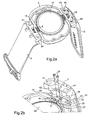
- tubular portions 22 are formed on each flange 20 to receive the corresponding end of the strand to be fixed to the housing.
- Each end of the strands comprises two openings 41 of complementary shapes to be fitted on the tubular portions 22.
- Fastening screws 40 shown in FIG. figure 2a , pass through each hole 21 of the tubular portions 22 and each opening 41 of the strands of the bracelet to be screwed into the threads of the upper part not shown. Thus, the bracelet is attached to the housing when the latter is closed.
- each end of the track conductive 7 is positioned on the second portion of the corresponding flange 8 so that the holes 18 and 42 are arranged substantially coaxially.
- the connecting screws 24 can be introduced into the holes 18 and 42 in order to be screwed into the threaded holes of the flange 20.
- this second portion can flex elastically when the connecting screw is screwed until it comes into contact with the upper surface of the flange.
- Each electrical contact flange 8 is introduced from its second part, whose end is narrowed, through each opening 31 formed in the portions 27 and 28 of the side wall 15. Thanks to this narrowing of the second part and the fact that the thickness of the blade is almost twice as small as the height of the opening 31, the introduction of this flange is facilitated. Said flange 8 is thus introduced through the openings 31 from the inside of the housing until the hole 18 of the second part is positioned substantially coaxially with the tapped hole 23 formed in the flange 20. The intermediate portion of the flange is thus positioned in the apertures 31 of the portions 27 and 28 thanks to the boss 29 whose height is substantially equal to the height of each opening 31.
- a specific tool 50 such as a syringe
- a specific tool 50 is brought into the cavity 26 to a certain distance from the bottom of the cavity for introducing the sealing material 9 in liquid form, such as polymerizable adhesive or silicone.
- the specific tool is guided in its descent by guiding means 16, also visible in the figures 1b , 2a and 2b .
- These guide means 16 made in part in each portion 27 and 28 of the side wall are located between the two flanges to be fixed.
- These guide means have a shape substantially complementary to the conical portion of the specific tool. This makes it possible to stop this tool during its descent into the cavity to a determined distance from the bottom of the cavity below each intermediate portion of the flanges positioned.
- the location of the specific tool in the cavity is shown by broken lines at the figure 3a .
- a predetermined amount of liquid polymerizable adhesive is introduced into the cavity from the lower end of the tool.
- the liquid adhesive 9 is spread in said cavity 26 by also closing each opening 31 of the portions 27 and 28 without overflow and by coating the intermediate portion of the flanges 8.
- the tool 50 is gradually removed from the cavity.
- the tool can introduce glue while leaving the cavity so that the level of the glue introduced reaches the upper edge of the cavity 26. From this moment, a certain period of time must be counted so that the glue solidifies as shown in figure 3b . This period of time can be of the order of 24 hours at room temperature.
- the adhesive is relatively elastic with good adhesion to the inner surfaces of the cavity 26, it allows sealing said flanges in the cavity 26 of the side wall 15 which is one of the aims of the invention.
- the outer portion 28 of the side wall comprises a flare 25 following the opening 31 passage of the flange.
- This flare 25 is provided to allow the second part of the flange, which is remote from the upper surface of the flange 20 in the rest position, to be able to bend without permanent deformation.
- this second flange portion can be attached with one end of the conductive track of the strap by means of the connecting screws until it comes into contact with the upper surface of the flange 20 as explained above.
- the assembly of all the components of the case and of the bracelet can be undertaken with in particular the printed circuit board which compresses the first part of each flange at the level of the contact pads when closing the housing.
- each flange in place of the boss of the intermediate portion of each flange, there is practiced two blisters to be housed each in an opening of each sidewall portion. It may be provided that one flange per cavity to connect each end of a single conductive track housed in the bracelet.
Landscapes
- Physics & Mathematics (AREA)
- General Physics & Mathematics (AREA)
- Electric Clocks (AREA)
Claims (12)
- Tragbarer Gegenstand (1), der ein Gehäuse (2, 3), in dem wenigstens eine elektronische Schaltung (11) angeordnet ist, ein Armband (4, 5), das an dem Gehäuse befestigt ist und wenigstens eine Leiterbahn (6, 7) aufweist, die in dem Armband (4, 5) angeordnet ist, und elektrische Anschlussmittel (8), um die wenigstens eine Leiterbahn (6, 7) des Armbands mit wenigstens einem Kontaktanschluss der elektronischen Schaltung zu verbinden, umfasst, wobei die elektrischen Anschlussmittel wenigstens einen Steg (8) für elektrischen Kontakt, der durch eine Durchgangsöffnung (31) in einer Seitenwand (15) des Gehäuses befestigt ist, umfasst, wobei ein erster Teil (8a) des Stegs in dem Gehäuse mit der elektronischen Schaltung (11) elektrisch verbunden ist und ein zweiter Teil (8b) des Stegs außerhalb des Gehäuses mit der Leiterbahn (6, 7) des Armbands elektrisch verbunden ist, dadurch gekennzeichnet, dass
die Seitenwand (15) einen Hohlraum (26) aufweist, der ausgehend von einem oberen Rand der Seitenwand angeordnet ist, um einen Boden, einen ersten inneren seitlichen Abschnitt (27) und einen zweiten äußeren seitlichen Abschnitt (28) der Seitenwand (15) zu definieren, wobei die Öffnung des Durchgangs (31) des Stegs in jedem der seitlichen Abschnitte (27, 28) der Seitenwand (15) ausgebildet ist, und dass ein Einkapselungsmaterial (9) in dem Hohlraum (26) zwischen den zwei seitlichen Abschnitten (27, 28) der Seitenwand (15) angeordnet ist, um einen Zwischenteil (8c) des Stegs, der durch den Hohlraum (26) verläuft, zu befestigen und jede Öffnung (31) der zwei seitlichen Abschnitte (27, 28) der Seitenwand (15) dicht zu verschließen. - Tragbarer Gegenstand nach Anspruch 1, dadurch gekennzeichnet, dass das Einkapselungsmaterial ein polymerisierbarer Klebstoff oder Silikon ist.
- Tragbarer Gegenstand nach einem der vorhergehenden Ansprüche, dadurch gekennzeichnet, dass der Zwischenteil (8c) und der zweite Teil (8b) der Metallbrücke die Form eines Plättchens haben.
- Tragbarer Gegenstand nach Anspruch 3, dadurch gekennzeichnet, dass wenigstens eine Erhebung (29), die insbesondere durch Prägen erhalten wird, in dem Zwischenteil (8c) des Plättchens ausgebildet ist, derart, dass die Höhe des Zwischenteils des Stegs im Wesentlichen gleich jener jeder Öffnung (31) der Wandabschnitte ist, um den Steg durch die Seitenwand hindurch zu positionieren.
- Tragbarer Gegenstand nach einem der Ansprüche 3 und 4, wobei das Gehäuse einen unteren Teil aus Isoliermaterial als Boden (2) des Gehäuses, das die Seitenwand (15) besitzt, einen oberen Teil als Ringwand (3), der an den unteren Teil angefügt ist, und Befestigungsmittel (40), um den unteren und den oberen Teil in einer geschlossenen Position des Gehäuses zusammenzuhalten, umfasst, wobei die elektronische Schaltung auf einer gedruckten Leiterplatte (10) montiert ist, die wenigstens einen Kontaktanschluss (30) aufweist, der mit dem Kontaktanschluss der elektronischen Schaltung verbunden ist, dadurch gekennzeichnet, dass der erste Teil (8a) des metallischen Stegs eine S-Form hat, die eine Feder bildet, die dazu bestimmt ist, bei einem Kontakt des Endes dieses ersten Teils des Stegs mit dem Kontaktanschluss der gedruckten Leiterplatte in der geschlossenen Position des Gehäuses zusammengedrückt zu werden.
- Tragbarer Gegenstand nach einem der vorhergehenden Ansprüche, dadurch gekennzeichnet, dass wenigstens ein isolierender äußerer Rand (20) für die Montage eines Endes eines Zweigs (4, 5) des Armbands in einem unteren Teil des Gehäuses in einer äußeren Verlängerung, die von der Seitenwand (15) an dem Ort ausgeht, wo der Zwischenteil (8c) des Stegs befestigt ist, ausgebildet ist, wobei in der Ruheposition der zweite äußere Teil des Stegs von einer oberen Oberfläche des Randes beabstandet ist, und dass der zweite Teil (8b) des Stegs und das Ende der Leiterbahn (6, 7) des Armbands jeweils ein Loch (18, 42) aufweisen, um aneinander insbesondere gegen die obere Oberfläche des Randes (20) mittels eines leitenden Stifts mit Kopf (24), der in ein Befestigungsloch (23) eingesetzt ist, das in dem Rand ausgebildet ist, befestigt werden zu können, wobei der Durchmesser der Löcher des zweiten Teils des Stegs und des Endes der Leiterbahn kleiner ist als der Durchmesser des Kopfes des Stifts und größer ist als der Durchmesser des Stifts.
- Tragbarer Gegenstand nach Anspruch 6, dadurch gekennzeichnet, dass der Stift mit Kopf eine Verbindungsschraube (24) ist, die in ein in dem Rand (20) ausgebildetes Loch (23) eingesetzt ist, um das Ende der Leiterbahn und den zweiten Teil des Stegs elektrisch zu verbinden, wobei jedes Loch des Randes durch eine Schraubverbindung mit Gewinde versehen ist oder ein Gewinde aufweist.
- Tragbarer Gegenstand nach einem der Ansprüche 1, 6 und 7, wobei zwei Enden der Leiterbahn des Armbands mit elektrischen Anschlussmitteln verbunden sind, wobei die Leiterbahn des Armbands eine Antenne zum Aussenden oder Empfangen von Datensignalen definiert, wobei die elektronische Schaltung mit einer Einheit für die Verarbeitung von Signalen versehen ist, die von der Antenne empfangen oder durch die Antenne ausgesendet werden, dadurch gekennzeichnet, dass zwei Stege (8) für elektrischen Kontakt, die relativ zueinander parallel angeordnet sind, jeweils durch eine entsprechende Öffnung (31) jedes Abschnitts (27, 28) der Seitenwand des Gehäuses desselben Hohlraums (26) verlaufen, wobei ein zweiter Teil jedes Stegs mit einem entsprechenden Ende der Leiterbahn verbunden ist, und dass das Einkapselungsmaterial (9) den Zwischenteil der zwei Stege im selben Hohlraum zwischen den zwei Wandabschnitten befestigt.
- Tragbarer Gegenstand nach einem der vorhergehenden Ansprüche, dadurch gekennzeichnet, dass die Seitenwand (15) zwei Hohlräume (26) umfasst, die diametral entgegengesetzt angeordnet sind, und dass ein oder zwei Stege pro Hohlraum durch das Einkapselungsmaterial (9), das zwischen dem ersten und dem zweiten Abschnitt (27, 28) der Wand jedes Hohlraums angeordnet ist, befestigt sind, wobei der zweite Teil (8b) jedes Stegs mit einem Ende einer Leiterbahn (6, 7) von einem oder von zwei Zweigen des Armbands verbunden ist, während der erste Teil (8a) jedes Stegs mit einem entsprechenden Kontaktanschluss (30) der gedruckten Leiterplatte, die die gedruckte Schaltung trägt, verbunden ist.
- Verfahren für die Montage von elektrischen Anschlussmitteln eines tragbaren Gegenstands (1) nach einem der Ansprüche 1 bis 9, wobei die Anschlussmittel wenigstens einen Steg (8) für elektrischen Kontakt umfassen, dadurch gekennzeichnet, dass es die folgenden Schritte umfasst:- Einsetzen wenigstens eines Stegs (8) für elektrischen Kontakt durch eine Öffnung (31) jedes seitlichen Abschnitts (27, 28) der Wand eines Hohlraums (26), die in der Seitenwand (15) des Gehäuses ausgebildet ist, derart, dass ein erster Teil (8a) des Stegs innerhalb des Gehäuses positioniert ist, um mit wenigstens einem Kontaktanschluss einer elektronischen Schaltung (11) elektrisch verbunden zu werden, und dass ein zweiter Teil (8b) des Stegs außerhalb des Gehäuses angeordnet ist, um mit wenigstens einer Leiterbahn (6, 7) des Armbands elektrisch verbunden zu werden, wobei die Abmessung jeder Öffnung gleich oder größer ist als der Querschnitt jedes Teils des Stegs,- Füllen des Hohlraums mit Hilfe eines Spezialwerkzeugs (50) mit einem Einkapselungsmaterial (9) in flüssiger Form und- Verfestigen des Einkapselungsmaterials, das in den Hohlraum eingeleitet worden ist, um den Zwischenteil des Stegs zu befestigen und um jede Öffnung der Wandabschnitte dicht zu verschließen.
- Verfahren nach Anspruch 10, dadurch gekennzeichnet, dass der Hohlraum (26) mit einem Einkapselungsmaterial (9) gefüllt wird, das ein polymerisierbarer Klebstoff oder Silikon ist.
- Verfahren nach Anspruch 10, wobei die Seitenwand (15) einen Teil des Bodens (2) des Gehäuses bildet, wobei der Hohlraum (26) ausgehend vom oberen Rand der Seitenwand in vertikaler Richtung ausgebildet ist, um durch die beiden seitlichen Wandabschnitte (27, 28) begrenzt zu sein, dadurch gekennzeichnet, dass ein Spezialwerkzeug (59) für die Befüllung mit dem Einkapselungsmaterial (9) in den Hohlraum bis zu einem bestimmten Abstand vom Boden des Hohlraums eingeführt wird, indem es durch Führungsmittel (16) geführt wird, die in jedem seitlichen Abschnitt (27, 28) der Seitenwand (15) ausgebildet sind, wobei die Führungsmittel eine zu dem Werkzeug komplementäre Form haben, derart, dass eine bestimmte Menge von Einkapselungsmaterial in den Hohlraum ausgehend von seinem Boden unterhalb des Zwischenteils (8c) des Stegs bis in die Umgebung des oberen Randes jedes seitlichen Abschnitts (27, 28) der Seitenwand (15) gefüllt wird.
Priority Applications (1)
| Application Number | Priority Date | Filing Date | Title |
|---|---|---|---|
| EP20040019954 EP1513222B1 (de) | 2003-09-03 | 2004-08-23 | Tragbares Armbandgerät mit elektrischem Verbindungselement durchs Gehäuse und Verfahren zur Montage des Verbindungselements |
Applications Claiming Priority (3)
| Application Number | Priority Date | Filing Date | Title |
|---|---|---|---|
| EP03020024 | 2003-09-03 | ||
| EP03020024A EP1513221A1 (de) | 2003-09-03 | 2003-09-03 | Tragbares Armbandgerät mit elektrischem Verbindungselement durchs Gehäuse und Verfahren zur Montage des Verbindungselements |
| EP20040019954 EP1513222B1 (de) | 2003-09-03 | 2004-08-23 | Tragbares Armbandgerät mit elektrischem Verbindungselement durchs Gehäuse und Verfahren zur Montage des Verbindungselements |
Publications (2)
| Publication Number | Publication Date |
|---|---|
| EP1513222A1 EP1513222A1 (de) | 2005-03-09 |
| EP1513222B1 true EP1513222B1 (de) | 2014-04-16 |
Family
ID=34137572
Family Applications (1)
| Application Number | Title | Priority Date | Filing Date |
|---|---|---|---|
| EP20040019954 Expired - Lifetime EP1513222B1 (de) | 2003-09-03 | 2004-08-23 | Tragbares Armbandgerät mit elektrischem Verbindungselement durchs Gehäuse und Verfahren zur Montage des Verbindungselements |
Country Status (1)
| Country | Link |
|---|---|
| EP (1) | EP1513222B1 (de) |
Family Cites Families (4)
| Publication number | Priority date | Publication date | Assignee | Title |
|---|---|---|---|---|
| DE8815967U1 (de) * | 1988-05-27 | 1989-09-21 | Junghans Uhren GmbH, 7230 Schramberg | Antenne für eine kleine Funkuhr |
| US5450091A (en) * | 1988-08-05 | 1995-09-12 | Seiko Epson Corporation | Variable size antenna device having resonance frequency compensation |
| US5135694A (en) * | 1989-11-10 | 1992-08-04 | Seiko Epson Corporation | Electronic device wristband |
| JP2985296B2 (ja) * | 1990-05-16 | 1999-11-29 | セイコーエプソン株式会社 | 電子機器のアンテナ接続装置 |
-
2004
- 2004-08-23 EP EP20040019954 patent/EP1513222B1/de not_active Expired - Lifetime
Also Published As
| Publication number | Publication date |
|---|---|
| EP1513222A1 (de) | 2005-03-09 |
Similar Documents
| Publication | Publication Date | Title |
|---|---|---|
| EP1513221A1 (de) | Tragbares Armbandgerät mit elektrischem Verbindungselement durchs Gehäuse und Verfahren zur Montage des Verbindungselements | |
| EP1416582B1 (de) | Tragbare elektronische Vorrichtung mit einer elektrischen Verbindung in dem Vorrichtungsgehäuse | |
| EP1672443B1 (de) | Uhr mit einem Drucksensor | |
| EP2741152B1 (de) | Armbanduhr, die mit einem elektrischen Steckverbinder ausgestattet ist | |
| EP1143573A1 (de) | Koaxialer Verbinder | |
| EP0156146B1 (de) | Piezoelektrischer Oszillator | |
| EP0766152A1 (de) | Uhr mit einer Antenne | |
| CA2257334A1 (fr) | Fixation d'un accessoire destine a un ensemble de bracelet et boitier porte au poignet | |
| WO2021250235A1 (fr) | Dispositif portable d'analyse continue d'un fluide corporel d'un patient | |
| EP1434114B1 (de) | Uhrengehäuse mit Boden oder Deckel mit Bajonettverschluss der manuell geöffnet werden kann | |
| FR2762150A1 (fr) | Connecteur d'entree/sortie pour dispositif portable de communication et procede de montage dudit connecteur | |
| EP2546614A1 (de) | Sensor- oder Detektorvorrichtung mit einem perfektionierten Kabelführungsstöpsel | |
| EP0186804B1 (de) | Am Armgelenk zu tragende elektronische Vorrichtung | |
| EP1519457B1 (de) | Adapter für ein tragbares elektronisches Gerät und Übertragungssystem zwischen diesen Bauteilen | |
| EP0024364A1 (de) | Vorrichtung zum Halten einer Batterie in einer elektronischen Armbanduhr | |
| EP1513222B1 (de) | Tragbares Armbandgerät mit elektrischem Verbindungselement durchs Gehäuse und Verfahren zur Montage des Verbindungselements | |
| FR2485220A1 (fr) | Bati et bloc modulaires pour instruments horaires | |
| EP1593317B1 (de) | Armband, insbesondere für eine Uhr, mit einem eingearbeiteten elektrisch leitenden Element | |
| FR2629662A1 (fr) | Capsule electroacoustique a bobine rapportee | |
| EP1538697B1 (de) | Tragbares Armbandgerät mit einer elektrischen Verbindungsvorrichtung durch das Gehäuse | |
| FR2479579A1 (fr) | Dispositif de fixation et de prise de contact electrique d'une pile dans une montre | |
| WO2013021119A2 (fr) | Dispositif de connexion electrique, ensemble comprenant un tel dispositif et une carte electronique et procede de connexion electrique d'une carte electronique | |
| EP1544696B1 (de) | Tragbares elektronisches Gerät, das mit einem Drucksensor ausgerüstet ist | |
| FR2807155A1 (fr) | Initiateur pyrotechnique pouvant etre equipe d'un composant electrique ou electronique et/ou d'un connecteur | |
| EP0370356A1 (de) | Uhrengehäuse mit einem gesinterten Mittelteil |
Legal Events
| Date | Code | Title | Description |
|---|---|---|---|
| PUAI | Public reference made under article 153(3) epc to a published international application that has entered the european phase |
Free format text: ORIGINAL CODE: 0009012 |
|
| AK | Designated contracting states |
Kind code of ref document: A1 Designated state(s): AT BE BG CH CY CZ DE DK EE ES FI FR GB GR HU IE IT LI LU MC NL PL PT RO SE SI SK TR |
|
| AX | Request for extension of the european patent |
Extension state: AL HR LT LV MK |
|
| RBV | Designated contracting states (corrected) |
Designated state(s): AT BE BG CH CY CZ DE DK EE ES FI FR GB GR HU IE IT LI LU MC NL PL PT RO SE SI SK TR |
|
| RBV | Designated contracting states (corrected) |
Designated state(s): AT BE BG CH CY CZ DE DK EE ES FI FR GB GR HU IE IT LI LU MC NL PL PT RO SE SI SK TR |
|
| 17P | Request for examination filed |
Effective date: 20050909 |
|
| AKX | Designation fees paid |
Designated state(s): CH DE FR LI |
|
| 17Q | First examination report despatched |
Effective date: 20070531 |
|
| RIC1 | Information provided on ipc code assigned before grant |
Ipc: G04G 17/06 20060101ALI20121207BHEP Ipc: G04G 21/04 20130101ALI20121207BHEP Ipc: H01Q 1/27 20060101AFI20121207BHEP |
|
| REG | Reference to a national code |
Ref country code: DE Ref legal event code: R079 Ref document number: 602004044824 Country of ref document: DE Free format text: PREVIOUS MAIN CLASS: H01Q0001270000 Ipc: G04R0060040000 |
|
| RIC1 | Information provided on ipc code assigned before grant |
Ipc: G04G 21/04 20130101ALI20130530BHEP Ipc: H01Q 1/27 20060101ALI20130530BHEP Ipc: G04G 17/06 20060101ALI20130530BHEP Ipc: G04R 60/04 20130101AFI20130530BHEP |
|
| GRAP | Despatch of communication of intention to grant a patent |
Free format text: ORIGINAL CODE: EPIDOSNIGR1 |
|
| INTG | Intention to grant announced |
Effective date: 20140102 |
|
| GRAS | Grant fee paid |
Free format text: ORIGINAL CODE: EPIDOSNIGR3 |
|
| GRAA | (expected) grant |
Free format text: ORIGINAL CODE: 0009210 |
|
| AK | Designated contracting states |
Kind code of ref document: B1 Designated state(s): CH DE FR LI |
|
| REG | Reference to a national code |
Ref country code: CH Ref legal event code: EP |
|
| REG | Reference to a national code |
Ref country code: DE Ref legal event code: R096 Ref document number: 602004044824 Country of ref document: DE Effective date: 20140528 |
|
| REG | Reference to a national code |
Ref country code: CH Ref legal event code: NV Representative=s name: ICB INGENIEURS CONSEILS EN BREVETS SA, CH |
|
| REG | Reference to a national code |
Ref country code: DE Ref legal event code: R097 Ref document number: 602004044824 Country of ref document: DE |
|
| PLBE | No opposition filed within time limit |
Free format text: ORIGINAL CODE: 0009261 |
|
| STAA | Information on the status of an ep patent application or granted ep patent |
Free format text: STATUS: NO OPPOSITION FILED WITHIN TIME LIMIT |
|
| 26N | No opposition filed |
Effective date: 20150119 |
|
| REG | Reference to a national code |
Ref country code: DE Ref legal event code: R097 Ref document number: 602004044824 Country of ref document: DE Effective date: 20150119 |
|
| REG | Reference to a national code |
Ref country code: FR Ref legal event code: PLFP Year of fee payment: 13 |
|
| REG | Reference to a national code |
Ref country code: FR Ref legal event code: PLFP Year of fee payment: 14 |
|
| REG | Reference to a national code |
Ref country code: FR Ref legal event code: PLFP Year of fee payment: 15 |
|
| PGFP | Annual fee paid to national office [announced via postgrant information from national office to epo] |
Ref country code: CH Payment date: 20230902 Year of fee payment: 20 |
|
| PGFP | Annual fee paid to national office [announced via postgrant information from national office to epo] |
Ref country code: FR Payment date: 20230720 Year of fee payment: 20 Ref country code: DE Payment date: 20230720 Year of fee payment: 20 |
|
| REG | Reference to a national code |
Ref country code: DE Ref legal event code: R071 Ref document number: 602004044824 Country of ref document: DE |
|
| REG | Reference to a national code |
Ref country code: CH Ref legal event code: PL |