EP1513222A1 - Tragbares Armbandgerät mit elektrischem Verbindungselement durchs Gehäuse und Verfahren zur Montage des Verbindungselements - Google Patents
Tragbares Armbandgerät mit elektrischem Verbindungselement durchs Gehäuse und Verfahren zur Montage des Verbindungselements Download PDFInfo
- Publication number
- EP1513222A1 EP1513222A1 EP04019954A EP04019954A EP1513222A1 EP 1513222 A1 EP1513222 A1 EP 1513222A1 EP 04019954 A EP04019954 A EP 04019954A EP 04019954 A EP04019954 A EP 04019954A EP 1513222 A1 EP1513222 A1 EP 1513222A1
- Authority
- EP
- European Patent Office
- Prior art keywords
- flange
- cavity
- housing
- side wall
- bracelet
- Prior art date
- Legal status (The legal status is an assumption and is not a legal conclusion. Google has not performed a legal analysis and makes no representation as to the accuracy of the status listed.)
- Granted
Links
- 238000000034 method Methods 0.000 title claims abstract description 10
- 230000000149 penetrating effect Effects 0.000 title 1
- 239000007788 liquid Substances 0.000 claims abstract description 8
- 239000003566 sealing material Substances 0.000 claims description 23
- 238000007789 sealing Methods 0.000 claims description 12
- 239000002184 metal Substances 0.000 claims description 9
- 229910052751 metal Inorganic materials 0.000 claims description 9
- 239000000853 adhesive Substances 0.000 claims description 5
- 230000001070 adhesive effect Effects 0.000 claims description 5
- 229920001296 polysiloxane Polymers 0.000 claims description 5
- 238000010079 rubber tapping Methods 0.000 claims description 4
- 230000000295 complement effect Effects 0.000 claims description 3
- 239000011810 insulating material Substances 0.000 claims description 3
- 239000004020 conductor Substances 0.000 abstract description 14
- 239000000463 material Substances 0.000 abstract description 10
- 238000005538 encapsulation Methods 0.000 abstract 4
- 239000003292 glue Substances 0.000 description 9
- 230000006835 compression Effects 0.000 description 2
- 238000007906 compression Methods 0.000 description 2
- 230000000694 effects Effects 0.000 description 2
- 230000005484 gravity Effects 0.000 description 2
- RYGMFSIKBFXOCR-UHFFFAOYSA-N Copper Chemical compound [Cu] RYGMFSIKBFXOCR-UHFFFAOYSA-N 0.000 description 1
- 239000000956 alloy Substances 0.000 description 1
- 229910045601 alloy Inorganic materials 0.000 description 1
- 230000005540 biological transmission Effects 0.000 description 1
- 239000011248 coating agent Substances 0.000 description 1
- 238000000576 coating method Methods 0.000 description 1
- 238000004891 communication Methods 0.000 description 1
- 229910052802 copper Inorganic materials 0.000 description 1
- 239000010949 copper Substances 0.000 description 1
- 230000005611 electricity Effects 0.000 description 1
- 235000015243 ice cream Nutrition 0.000 description 1
- 230000010365 information processing Effects 0.000 description 1
- 239000004973 liquid crystal related substance Substances 0.000 description 1
- 239000007769 metal material Substances 0.000 description 1
- 230000003647 oxidation Effects 0.000 description 1
- 238000007254 oxidation reaction Methods 0.000 description 1
- 230000002093 peripheral effect Effects 0.000 description 1
- 230000000284 resting effect Effects 0.000 description 1
- 229910052594 sapphire Inorganic materials 0.000 description 1
- 239000010980 sapphire Substances 0.000 description 1
- 125000006850 spacer group Chemical group 0.000 description 1
- 210000000707 wrist Anatomy 0.000 description 1
Images

Classifications
-
- G—PHYSICS
- G04—HOROLOGY
- G04G—ELECTRONIC TIME-PIECES
- G04G17/00—Structural details; Housings
- G04G17/02—Component assemblies
- G04G17/06—Electric connectors, e.g. conductive elastomers
-
- G—PHYSICS
- G04—HOROLOGY
- G04G—ELECTRONIC TIME-PIECES
- G04G21/00—Input or output devices integrated in time-pieces
- G04G21/04—Input or output devices integrated in time-pieces using radio waves
-
- G—PHYSICS
- G04—HOROLOGY
- G04R—RADIO-CONTROLLED TIME-PIECES
- G04R60/00—Constructional details
- G04R60/04—Antennas attached to or integrated in watch bracelets
-
- H—ELECTRICITY
- H01—ELECTRIC ELEMENTS
- H01Q—ANTENNAS, i.e. RADIO AERIALS
- H01Q1/00—Details of, or arrangements associated with, antennas
- H01Q1/27—Adaptation for use in or on movable bodies
- H01Q1/273—Adaptation for carrying or wearing by persons or animals
Definitions
- the present invention relates to a portable object with a bracelet provided with means electrical connection through the housing.
- the portable object essentially comprises the housing in which is disposed at least one electronic circuit, an attached bracelet to the housing, and the electrical connection means for electrically connecting at least a conductive track of the bracelet to at least one contact terminal of the circuit electronic.
- the present invention also relates to an electrical contact flange for a portable bracelet object.
- the present invention also relates to a mounting method in particular the electrical contact flange for a portable object bracelet.
- the term "means of connection” any conductor or set of conductors to ensure electrical connection between at least one contact terminal of an electronic circuit and at less a conductive track disposed in the bracelet.
- This conductive track can be an antenna for transmitting and receiving signals or to connect electrically an electrical component contained in the bracelet and the circuit electronic in the case.
- the portable object is made in the form a portable electronic instrument in the form of a wristwatch.
- This wristwatch may comprise receiving means or radiofrequency-type signals if the conductive track of the bracelet defines an antenna.
- the electronic signal processing circuit electrical devices makes it possible to manage the transmission or reception of information signals by the antenna.
- European Patent No. 0 631 341 describes an electronic instrument of the type wristwatch having an antenna housed in the bracelet and connected to a electronic circuit for processing the signals received by the antenna.
- the circuit electronic processing is arranged inside the housing of the instrument on a printed circuit board.
- Connection pads are provided on a region peripheral of the printed circuit board to allow the establishment of a electrical connection between the electronic signal processing circuit and the connection terminals of the antenna which passes through a side wall of the housing.
- fastening screws pass through adapted openings antenna terminals to be screwed directly into the circuit board printed at the connection pads to ensure the electrical connection.
- a connector of the leaf spring type fixed to the printed circuit board for each terminal of the antenna, on which comes to rest an electrical conductor connected to one of the terminals of the antenna.
- Each conductor connected to an antenna terminal must cross the wall side to support the spring blade to establish electrical contact.
- a seal annular sealing is provided around said conductor in the passage through the side wall,
- a disadvantage of the electronic instrument presented in the European patent No. 0 631 341 is that part of the antenna must pass through a side wall of the housing in order to be directly connected to the printed circuit board. Thereby, sealing at the side wall of the housing, even with the annular seal, is not guaranteed in time and according to the handling of the bracelet.
- Another disadvantage of the first embodiment with fixing screws is that a subsequent replacement of the antenna in case of problem makes it essential a complete disassembly of the housing of the instrument, before being able to access the screws of fixation, which can make this operation tedious.
- US Pat. No. 5,168,281 which describes a device for antenna connection for electronic equipment, such as a wristwatch.
- An antenna end housed in a strand of the bracelet is fixed jointly to a electrical conductor.
- This conductor passes through a side wall of the housing in order to come connect a contact blade of a circuit board carrying a circuit electronic.
- An annular seal is provided around the driver in the passage to through the side wall.
- the main purpose of the invention is thus to overcome the disadvantages of the art prior to supplying a portable bracelet object provided with connection means through a side wall of the housing in a sealed manner without being disturbed in particular by various manipulations of the bracelet.
- the invention relates to a portable object cited above which is characterized in that the electrical connection means comprise at least one electrical contact flange fixed through a side wall of the housing, a first part of the flange in the housing being electrically connected to the electronic circuit and a second portion of the flange on the outside of the housing being electrically connected to the conductive track of the bracelet, in that the side wall comprises a cavity between first and second portions of the side wall, a passage opening of the flange being made in each side wall portion, and that a material seal is placed in the cavity between the two wall portions to secure a intermediate part of the flange and seal off each opening of the portions wall.
- An advantage of the wearable bracelet object according to the invention lies in the fact that the intermediate part of each flange is fixed by a sealing material introduced into a cavity formed between a first and a second portion of the side wall.
- the sealing material completely surrounds the flange in the cavity which may be a metal blade, and closes the passage openings of said flange.
- This sealing material is different from the insulating material used for the wall lateral.
- the sealing of said flange through the side wall is because the properties of the sealing material do not change during time in the same way as the side wall. He could of course have been imagined to overmould directly the contact flange in the side wall in hard plastic, but sealing problems would occur in the long run especially with a flange in the form of a metal blade.
- the sealing material is a polymerizable adhesive or silicone that solidifies at room temperature for a period of time that can be around 24 hours.
- the first part of the metal flange inside the housing is advantageously in the form of S to form a compression spring.
- a printed circuit board carrying the circuit electronics compresses the first part of the flange at a contact pad of said plate. A better electrical contact is thus ensured, because the first part of the compressed flange exerts a contact force against the contact pad of said plate.
- the second part of the metal flange in the form of a blade is arranged above from an upper surface of a mounting flange of the wrist strap to the rest, that is to say before the electrical connection to the conductive track of the bracelet.
- This second part comprises a hole adapted to the passage of a metal screw of connection that is screwed into a hole in the rim.
- the end of the track conductive also comprises a hole adapted to the passage of a metal screw.
- each hole in the plastic edge may not include initial tapping, the latter being performed for the first time simply by screwing of the connection screw.
- the portable object is a wristwatch presenting means of communication using waves radio frequencies. It is therefore expected to house an antenna in the bracelet, which is constituted by the conductive track. This antenna is connected to at least one circuit electronic processing of information signals received or transmitted by the antenna.
- a good seal is ensured to connect the antenna to the electronic processing circuit while presenting a good behavior in time.
- Another object of the invention is to provide a contact flange for means of electrical connection of a portable object to overcome the disadvantages of art earlier cited above.
- the invention relates to a contact flange which is characterized in that that a first part of the flange has a S shape constituting a spring in order to can be compressed to establish an electrical connection with a contact pad of a printed circuit board, and that an intermediate part and a second part of the flange have a blade shape.
- the specific tool for filling the cavity of the material of sealing is guided by guiding means provided in each portion of side wall up to a determined distance from the bottom of the cavity, but below each flange passing through said cavity.
- guiding means provided in each portion of side wall up to a determined distance from the bottom of the cavity, but below each flange passing through said cavity.
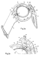
- FIG. 1a shows a schematic sectional view of the wristwatch 1 as a portable object.
- This wristwatch 1 comprises a housing having a upper part or middle part 3 and a lower part or bottom 2, a bracelet provided with two strands 4 and 5 attached to the housing, and at least one button or crown of command not shown.
- the upper 3 and lower 2 parts are assembled one on the other in the closed position of the housing with one of the ends of each strand 4 and 5 by conventional fastening means not shown in FIG. Figure 1a.
- Said ends of the strands 4 and 5 are wedged between the bottom 2 and the middle part 3.
- An annular seal 17 is placed in an annular groove of the middle part to come into contact with an upper edge of a side wall 15 of the bottom 2 in order to to ensure the tightness of the closed housing.
- This housing is further closed on the top by an ice cream 13 of conventional type and made for example of plastic or sapphire according to the desired level of range.
- a battery or accumulator 14 in a housing of the bottom 2 of the housing, a printed circuit board 10 on which is mounted at least one electronic circuit 11 powered by the battery or the accumulator, and an LCD liquid crystal device 12 to display in particular hourly, textual or other information.
- the display device 12 is controlled by the electronic circuit 11.
- Electrical conduction tracks not shown are arranged on the printed circuit board to connect electrically including electrical contact pads 30 disposed at the periphery of said plate to terminals of the electronic circuit 11.
- An intermediate spacing element 32 is disposed between the LCD device 12 and the printed circuit board 10 to ensure a sufficient height between these two elements and allow the arrangement of components, such as the circuit electronics 11 shown in the intermediate space thus defined.
- the wristwatch also comprises means of electrical connection which comprise in particular electrical contact flanges 8, which are in this embodiment in number of 4 as shown in particular in Figure 1b.
- these flanges 8 are intended to contact electrically the contact pads 30 on the printed circuit board 10 with ends of at least one conductive track 6 and 7 disposed in each strand 4 and 5 of the bracelet.
- the conductive track 6 and 7 of each strand defines a antenna for transmitting and receiving information in cooperation with the circuit electronic.
- the electronic circuit 11, which is placed inside the watch case 1, includes an information processing unit.
- the side wall 15 comprises two cavities 26 made from an upper edge of said wall in a vertical direction to define a bottom, a first inner portion 27 and a second outer portion 28 of the wall 15. These cavities are disposed in the side wall 15 in opposition diametrically, and located at the connection of each end of the strands 4 and 5 of the bracelet to the case.
- Two pairs of contact flanges 8 which are placed parallel to one another, pass through openings of two wall portions 27 and 28 of the two cavities 26 of the side wall 15 of the bottom 2.
- the intermediate portion of each pair of flanges 8 is secured by a sealing material 9 not shown in Figure 1b, which is introduced in each cavity 26 as described below with particular reference to Figures 3a and 3b.
- the sealing material is preferably a polymerizable adhesive or silicone.
- This sealing material 9 is different from the plastic insulating material used in particular for the side wall 15. In this way, the sealing of said flange 8 through the side wall 15 is tight because the properties of the material of sealing do not change over time in the same way as the wall lateral, which is for example hard plastic.
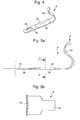
- connection means electric is shown more clearly in Figure 4 which represents a view three-dimensional of this flange, as well as in Figures 5a and 5b.
- This contact flange 8 is made from a band of a good conductor metal material electricity, such as an alloy composed of copper. The thickness of this band can be of the order of 0.1 mm.
- the flange comprises a first part 8a in S-shape, a second part 8b and the intermediate part 8c which is intended to be fixed through the side wall of the bottom of the housing by the sealing material.
- the first S-shaped portion 8a of the flange 8 constitutes a spring of compression.
- the printed circuit board compresses with a determined force F each first part of the flanges 8 to level of the contact pads of the printed circuit board. This makes it possible to establish a good electrical contact between the flange and the corresponding contact pad.
- the first one part 8a of the flange 8 thus compressed is shown in phantom in the figure 5a.
- the printed circuit board 10 rests on a spacer 19 separating it from the stack 14. This may also make it possible not to unnecessarily damage the first part of each flange 8 at the time of the closing the housing.
- the intermediate part 8c and the second part 8b of the flange have a general blade shape.
- the second part 8b of this flange is pierced with a hole 18 so as to be attached to one end of a track conductive as explained below.
- the end of the second part 8b of the flange is narrowed to facilitate mounting of the flange through the openings of the wall portions accommodating it before fixing it with the material of sealing.
- a boss 29 may be practiced in particular by stamping or stamping in the intermediate portion 8c of this flange to be able to position said flange in openings in each sidewall portion.
- Each opening is thus formed of sufficient size in said wall portions to facilitate the introduction of the second part.
- the height of each opening can be for example 0.2 mm, while the thickness of the second part is 0.1 mm.
- the height of the boss can be substantially equal to the height of each opening which allows to properly position the intermediate part of the flange before the introduction of the sealing material into the cavity of the side wall.
- the width of each opening of the wall portions receiving a flange can be substantially equal to or slightly greater than the width of the flange.
- each flange 8 is thus connected to a respective end of a conductive track 6 and 7 defining in particular an antenna of each strand 4 and 5 of the bracelet.
- This electrical connection is made by means of head rods, such as connection 24 screwed into respective holes 23 formed in a plastic rim 20 of the bottom 2 in extension of the side wall 15.
- Each hole can be self-tapped by the connection screw or may initially comprise a tapping.
- connection screws 24 passes through a suitable hole 18 of the second part of the flange 8 and a suitable hole 42 of the end of the track conductive 6 and 7 corresponding to connect. Since the head of the screw is larger diameter than the holes 18 and 42, the second part of the flange and the end of the conductive track can come into direct contact with the surface upper insulating flange 20 by completely screwing each connection screw 24 in the threaded holes 23.
- each strand 4 and 5 of the bracelet is fixed to the housing between the flange 20 of the bottom in extension of the side wall 15 and the middle part 3 by the fastening means which hold the upper part 3 on the lower part 2 of the housing.
- each tubular portion 22 are formed on each rim 20 to receive the corresponding end of the strand to fix to the housing.
- Each end of the strands comprises two openings 41 of complementary shapes to be fitted on the tubular portions 22.
- Screws 40 shown in Figure 2a, pass through each hole 21 portions tubular 22 and each opening 41 strands of the bracelet to be screwed into tapping of the upper part not shown. Thus, the bracelet is fixed at housing when the latter is closed.
- each end of the track 7 is positioned on the second part of the corresponding flange 8 of whereby the holes 18 and 42 are arranged substantially coaxially.
- the connection screws 24 can be introduced into the holes 18 and 42 so that they can be screwed into the threaded holes 20.
- this second part of the flange 8 is distant from the surface upper flange 20, this second part can flex elastically when the screw connection is screwed into contact with the upper surface of the flange.
- a good electrical connection is established between each flange and the end corresponding to the conductive track.
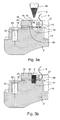
- Each electrical contact flange 8 is introduced from its second part, whose end is narrowed, through each opening 31 made in the portions 27 and 28 of the side wall 15. Due to this narrowing of the second part and the the thickness of the blade is almost twice as small as the height of the opening 31, the introduction of this flange is facilitated. Said flange 8 is therefore introduced through the openings 31 from the inside of the housing until the hole 18 of the second part is positioned substantially coaxially with the hole tapped 23 formed in the flange 20. The intermediate portion of the flange is thus positioned in the openings 31 of the portions 27 and 28 thanks to the boss 29 whose height is substantially equal to the height of each opening 31.
- a specific tool 50 such as a syringe
- a specific tool 50 is brought into the cavity 26 to a certain distance from the bottom of the cavity to introduce the material of sealing 9 in liquid form, such as polymerizable glue or silicone.
- the tool specific is guided in its descent by guiding means 16, visible also in Figures 1b, 2a and 2b.
- These guide means 16 made in part in each portion 27 and 28 of the side wall are located between the two flanges at to stare.
- These guide means have a shape substantially complementary to the part taper of the specific tool. This allows to stop this tool during its descent in the cavity to a determined distance from the bottom of the cavity below each intermediate portion of the flanges positioned.
- the location of the tool specific in the cavity is shown by dashed lines in Figure 3a.
- a determined quantity of glue polymerizable liquid is introduced into the cavity from the lower end of the tool.
- the liquid adhesive 9 spreads in said cavity 26 also by plugging each opening 31 portions 27 and 28 without overflow and coating the part intermediate flanges 8.
- the tool 50 is gradually withdrawn from the cavity.
- the tool can introduce glue while leaving the cavity so that the level of the glue introduced reaches the upper edge of the cavity 26. From this moment, a certain period of time must be counted so that the glue solidifies as shown in Figure 3b. This period of time can be of the order of 24 hours at room temperature.
- the glue is relatively elastic with good adhesion to surfaces interior of the cavity 26, this makes it possible to seal said flanges in the cavity 26 of the side wall 15 which is one of the aims of the invention.
- the outer portion 28 of the side wall comprises a flare 25 following the opening 31 of passage of the flange.
- This flare 25 is intended to allow the second part of the flange, which is distant from the upper surface of the flange 20 in the position of rest, to be able to flex without permanent deformation. In this way, this second flange part can be attached with one end of the conductive track of the strap by means of the connecting screws until coming into contact with the upper surface of the flange 20 as explained above.
- the assembly of all the components of the case and the bracelet can be undertaken with especially the printed circuit board that compresses the first part of each flange at the contact pads when closing the housing.
Landscapes
- Physics & Mathematics (AREA)
- General Physics & Mathematics (AREA)
- Electric Clocks (AREA)
Priority Applications (1)
| Application Number | Priority Date | Filing Date | Title |
|---|---|---|---|
| EP20040019954 EP1513222B1 (de) | 2003-09-03 | 2004-08-23 | Tragbares Armbandgerät mit elektrischem Verbindungselement durchs Gehäuse und Verfahren zur Montage des Verbindungselements |
Applications Claiming Priority (3)
| Application Number | Priority Date | Filing Date | Title |
|---|---|---|---|
| EP03020024 | 2003-09-03 | ||
| EP03020024A EP1513221A1 (de) | 2003-09-03 | 2003-09-03 | Tragbares Armbandgerät mit elektrischem Verbindungselement durchs Gehäuse und Verfahren zur Montage des Verbindungselements |
| EP20040019954 EP1513222B1 (de) | 2003-09-03 | 2004-08-23 | Tragbares Armbandgerät mit elektrischem Verbindungselement durchs Gehäuse und Verfahren zur Montage des Verbindungselements |
Publications (2)
| Publication Number | Publication Date |
|---|---|
| EP1513222A1 true EP1513222A1 (de) | 2005-03-09 |
| EP1513222B1 EP1513222B1 (de) | 2014-04-16 |
Family
ID=34137572
Family Applications (1)
| Application Number | Title | Priority Date | Filing Date |
|---|---|---|---|
| EP20040019954 Expired - Lifetime EP1513222B1 (de) | 2003-09-03 | 2004-08-23 | Tragbares Armbandgerät mit elektrischem Verbindungselement durchs Gehäuse und Verfahren zur Montage des Verbindungselements |
Country Status (1)
| Country | Link |
|---|---|
| EP (1) | EP1513222B1 (de) |
Citations (4)
| Publication number | Priority date | Publication date | Assignee | Title |
|---|---|---|---|---|
| US4947179A (en) * | 1988-05-27 | 1990-08-07 | Junghans Uhren Gmbh | Antenna for a radio controlled timepiece |
| US5168281A (en) * | 1990-05-16 | 1992-12-01 | Seiko Epson Corporation | Antenna connection device for electronic equipment |
| US5450091A (en) * | 1988-08-05 | 1995-09-12 | Seiko Epson Corporation | Variable size antenna device having resonance frequency compensation |
| US5526006A (en) * | 1989-11-10 | 1996-06-11 | Seiko Epson Corporation | Electronic device wristband |
-
2004
- 2004-08-23 EP EP20040019954 patent/EP1513222B1/de not_active Expired - Lifetime
Patent Citations (4)
| Publication number | Priority date | Publication date | Assignee | Title |
|---|---|---|---|---|
| US4947179A (en) * | 1988-05-27 | 1990-08-07 | Junghans Uhren Gmbh | Antenna for a radio controlled timepiece |
| US5450091A (en) * | 1988-08-05 | 1995-09-12 | Seiko Epson Corporation | Variable size antenna device having resonance frequency compensation |
| US5526006A (en) * | 1989-11-10 | 1996-06-11 | Seiko Epson Corporation | Electronic device wristband |
| US5168281A (en) * | 1990-05-16 | 1992-12-01 | Seiko Epson Corporation | Antenna connection device for electronic equipment |
Also Published As
| Publication number | Publication date |
|---|---|
| EP1513222B1 (de) | 2014-04-16 |
Similar Documents
| Publication | Publication Date | Title |
|---|---|---|
| EP1513221A1 (de) | Tragbares Armbandgerät mit elektrischem Verbindungselement durchs Gehäuse und Verfahren zur Montage des Verbindungselements | |
| EP1416582B1 (de) | Tragbare elektronische Vorrichtung mit einer elektrischen Verbindung in dem Vorrichtungsgehäuse | |
| EP1672443A1 (de) | Uhr mit einem Drucksensor | |
| EP2741152A1 (de) | Armbanduhr, die mit einem elektrischen Steckverbinder ausgestattet ist | |
| EP0766152A1 (de) | Uhr mit einer Antenne | |
| EP0156146B1 (de) | Piezoelektrischer Oszillator | |
| EP1489471A1 (de) | Erdung von einer gedruckten Schaltung eingestellt in einen Armband elektronischen Gerät | |
| FR2807573A1 (fr) | Connecteur coaxial | |
| EP1274150A1 (de) | Armbanduhr mit Antenne | |
| EP2687919A1 (de) | Antistoss-Befestigungsmittel eines Elektronikmoduls mit einem Quarzresonator | |
| EP1434114B1 (de) | Uhrengehäuse mit Boden oder Deckel mit Bajonettverschluss der manuell geöffnet werden kann | |
| EP3457222A1 (de) | Armbanduhrengehäuse mit beweglichen bandanstössen | |
| FR2762150A1 (fr) | Connecteur d'entree/sortie pour dispositif portable de communication et procede de montage dudit connecteur | |
| EP0024364A1 (de) | Vorrichtung zum Halten einer Batterie in einer elektronischen Armbanduhr | |
| EP0186804B1 (de) | Am Armgelenk zu tragende elektronische Vorrichtung | |
| EP1519457B1 (de) | Adapter für ein tragbares elektronisches Gerät und Übertragungssystem zwischen diesen Bauteilen | |
| FR2485220A1 (fr) | Bati et bloc modulaires pour instruments horaires | |
| EP1513222B1 (de) | Tragbares Armbandgerät mit elektrischem Verbindungselement durchs Gehäuse und Verfahren zur Montage des Verbindungselements | |
| EP1593317B1 (de) | Armband, insbesondere für eine Uhr, mit einem eingearbeiteten elektrisch leitenden Element | |
| FR2629662A1 (fr) | Capsule electroacoustique a bobine rapportee | |
| FR2479579A1 (fr) | Dispositif de fixation et de prise de contact electrique d'une pile dans une montre | |
| EP1538697B1 (de) | Tragbares Armbandgerät mit einer elektrischen Verbindungsvorrichtung durch das Gehäuse | |
| EP0718910A1 (de) | Armbanduhr mit Hochfrequenzsender | |
| EP0269872B1 (de) | Uhrengehäuse | |
| EP1544696B1 (de) | Tragbares elektronisches Gerät, das mit einem Drucksensor ausgerüstet ist |
Legal Events
| Date | Code | Title | Description |
|---|---|---|---|
| PUAI | Public reference made under article 153(3) epc to a published international application that has entered the european phase |
Free format text: ORIGINAL CODE: 0009012 |
|
| AK | Designated contracting states |
Kind code of ref document: A1 Designated state(s): AT BE BG CH CY CZ DE DK EE ES FI FR GB GR HU IE IT LI LU MC NL PL PT RO SE SI SK TR |
|
| AX | Request for extension of the european patent |
Extension state: AL HR LT LV MK |
|
| RBV | Designated contracting states (corrected) |
Designated state(s): AT BE BG CH CY CZ DE DK EE ES FI FR GB GR HU IE IT LI LU MC NL PL PT RO SE SI SK TR |
|
| RBV | Designated contracting states (corrected) |
Designated state(s): AT BE BG CH CY CZ DE DK EE ES FI FR GB GR HU IE IT LI LU MC NL PL PT RO SE SI SK TR |
|
| 17P | Request for examination filed |
Effective date: 20050909 |
|
| AKX | Designation fees paid |
Designated state(s): CH DE FR LI |
|
| 17Q | First examination report despatched |
Effective date: 20070531 |
|
| RIC1 | Information provided on ipc code assigned before grant |
Ipc: G04G 17/06 20060101ALI20121207BHEP Ipc: G04G 21/04 20130101ALI20121207BHEP Ipc: H01Q 1/27 20060101AFI20121207BHEP |
|
| REG | Reference to a national code |
Ref country code: DE Ref legal event code: R079 Ref document number: 602004044824 Country of ref document: DE Free format text: PREVIOUS MAIN CLASS: H01Q0001270000 Ipc: G04R0060040000 |
|
| RIC1 | Information provided on ipc code assigned before grant |
Ipc: G04G 21/04 20130101ALI20130530BHEP Ipc: H01Q 1/27 20060101ALI20130530BHEP Ipc: G04G 17/06 20060101ALI20130530BHEP Ipc: G04R 60/04 20130101AFI20130530BHEP |
|
| GRAP | Despatch of communication of intention to grant a patent |
Free format text: ORIGINAL CODE: EPIDOSNIGR1 |
|
| INTG | Intention to grant announced |
Effective date: 20140102 |
|
| GRAS | Grant fee paid |
Free format text: ORIGINAL CODE: EPIDOSNIGR3 |
|
| GRAA | (expected) grant |
Free format text: ORIGINAL CODE: 0009210 |
|
| AK | Designated contracting states |
Kind code of ref document: B1 Designated state(s): CH DE FR LI |
|
| REG | Reference to a national code |
Ref country code: CH Ref legal event code: EP |
|
| REG | Reference to a national code |
Ref country code: DE Ref legal event code: R096 Ref document number: 602004044824 Country of ref document: DE Effective date: 20140528 |
|
| REG | Reference to a national code |
Ref country code: CH Ref legal event code: NV Representative=s name: ICB INGENIEURS CONSEILS EN BREVETS SA, CH |
|
| REG | Reference to a national code |
Ref country code: DE Ref legal event code: R097 Ref document number: 602004044824 Country of ref document: DE |
|
| PLBE | No opposition filed within time limit |
Free format text: ORIGINAL CODE: 0009261 |
|
| STAA | Information on the status of an ep patent application or granted ep patent |
Free format text: STATUS: NO OPPOSITION FILED WITHIN TIME LIMIT |
|
| 26N | No opposition filed |
Effective date: 20150119 |
|
| REG | Reference to a national code |
Ref country code: DE Ref legal event code: R097 Ref document number: 602004044824 Country of ref document: DE Effective date: 20150119 |
|
| REG | Reference to a national code |
Ref country code: FR Ref legal event code: PLFP Year of fee payment: 13 |
|
| REG | Reference to a national code |
Ref country code: FR Ref legal event code: PLFP Year of fee payment: 14 |
|
| REG | Reference to a national code |
Ref country code: FR Ref legal event code: PLFP Year of fee payment: 15 |
|
| PGFP | Annual fee paid to national office [announced via postgrant information from national office to epo] |
Ref country code: CH Payment date: 20230902 Year of fee payment: 20 |
|
| PGFP | Annual fee paid to national office [announced via postgrant information from national office to epo] |
Ref country code: FR Payment date: 20230720 Year of fee payment: 20 Ref country code: DE Payment date: 20230720 Year of fee payment: 20 |
|
| REG | Reference to a national code |
Ref country code: DE Ref legal event code: R071 Ref document number: 602004044824 Country of ref document: DE |
|
| REG | Reference to a national code |
Ref country code: CH Ref legal event code: PL |