EP0181260A2 - Mounting and protecting device for the operating means of folding doors - Google Patents
Mounting and protecting device for the operating means of folding doors Download PDFInfo
- Publication number
- EP0181260A2 EP0181260A2 EP85402115A EP85402115A EP0181260A2 EP 0181260 A2 EP0181260 A2 EP 0181260A2 EP 85402115 A EP85402115 A EP 85402115A EP 85402115 A EP85402115 A EP 85402115A EP 0181260 A2 EP0181260 A2 EP 0181260A2
- Authority
- EP
- European Patent Office
- Prior art keywords
- door
- motor element
- straps
- horizontal
- motor
- Prior art date
- Legal status (The legal status is an assumption and is not a legal conclusion. Google has not performed a legal analysis and makes no representation as to the accuracy of the status listed.)
- Granted
Links
Images


Classifications
-
- E—FIXED CONSTRUCTIONS
- E06—DOORS, WINDOWS, SHUTTERS, OR ROLLER BLINDS IN GENERAL; LADDERS
- E06B—FIXED OR MOVABLE CLOSURES FOR OPENINGS IN BUILDINGS, VEHICLES, FENCES OR LIKE ENCLOSURES IN GENERAL, e.g. DOORS, WINDOWS, BLINDS, GATES
- E06B9/00—Screening or protective devices for wall or similar openings, with or without operating or securing mechanisms; Closures of similar construction
- E06B9/02—Shutters, movable grilles, or other safety closing devices, e.g. against burglary
- E06B9/08—Roll-type closures
- E06B9/11—Roller shutters
- E06B9/17—Parts or details of roller shutters, e.g. suspension devices, shutter boxes, wicket doors, ventilation openings
- E06B9/17007—Shutter boxes; Details or component parts thereof
-
- E—FIXED CONSTRUCTIONS
- E06—DOORS, WINDOWS, SHUTTERS, OR ROLLER BLINDS IN GENERAL; LADDERS
- E06B—FIXED OR MOVABLE CLOSURES FOR OPENINGS IN BUILDINGS, VEHICLES, FENCES OR LIKE ENCLOSURES IN GENERAL, e.g. DOORS, WINDOWS, BLINDS, GATES
- E06B9/00—Screening or protective devices for wall or similar openings, with or without operating or securing mechanisms; Closures of similar construction
- E06B9/02—Shutters, movable grilles, or other safety closing devices, e.g. against burglary
- E06B9/06—Shutters, movable grilles, or other safety closing devices, e.g. against burglary collapsible or foldable, e.g. of the bellows or lazy-tongs type
- E06B9/0607—Shutters, movable grilles, or other safety closing devices, e.g. against burglary collapsible or foldable, e.g. of the bellows or lazy-tongs type comprising a plurality of similar rigid closing elements movable to a storage position
- E06B9/0646—Shutters, movable grilles, or other safety closing devices, e.g. against burglary collapsible or foldable, e.g. of the bellows or lazy-tongs type comprising a plurality of similar rigid closing elements movable to a storage position characterised by the relative arrangement of the closing elements in the stored position
- E06B9/0669—Shutters, movable grilles, or other safety closing devices, e.g. against burglary collapsible or foldable, e.g. of the bellows or lazy-tongs type comprising a plurality of similar rigid closing elements movable to a storage position characterised by the relative arrangement of the closing elements in the stored position stored in a zig-zag arrangement
-
- E—FIXED CONSTRUCTIONS
- E06—DOORS, WINDOWS, SHUTTERS, OR ROLLER BLINDS IN GENERAL; LADDERS
- E06B—FIXED OR MOVABLE CLOSURES FOR OPENINGS IN BUILDINGS, VEHICLES, FENCES OR LIKE ENCLOSURES IN GENERAL, e.g. DOORS, WINDOWS, BLINDS, GATES
- E06B9/00—Screening or protective devices for wall or similar openings, with or without operating or securing mechanisms; Closures of similar construction
- E06B9/02—Shutters, movable grilles, or other safety closing devices, e.g. against burglary
- E06B9/06—Shutters, movable grilles, or other safety closing devices, e.g. against burglary collapsible or foldable, e.g. of the bellows or lazy-tongs type
- E06B9/0692—Shutters, movable grilles, or other safety closing devices, e.g. against burglary collapsible or foldable, e.g. of the bellows or lazy-tongs type comprising flexible sheets as closing screen
Definitions
- the present invention relates to a device for fixing and protecting the motor element of accordion doors.
- motor element is meant the motor, the motor control means, the strap winding shaft, the limit switch element, the electrical cabinet, etc.
- accordion doors can have a large surface area and are ideal for industrial installations, warehouses, hangars, etc.
- an accordion door comprises a flexible curtain stiffened at regular intervals by horizontal reinforcing bars or a series of articulated horizontal panels; lifting straps fixed at one end to the lower rebar of the flexible curtain or at the base of the lower panel and at the other end to a winding shaft whose rotation is controlled by a motor.
- the lifting straps preferably pass through guides arranged on some of the rebar, or on some of the joints connecting two consecutive panels.
- the base of the lower panel in the case of an accordion door with panels, or some of the reinforcing bars, the lower bar of which in the case of an accordion door with flexible curtain, has a roller at each of their ends which slides in a side guide in the door jambs.
- the strap winding shaft which overhangs the door, pivots in bearings fixed inside a U-shaped metal beam, - the base of the U being horizontal and placed upwards -, which forms the lintel.
- the motor causing the rotation of the strap winding shaft is fixed along one of the door jambs near the top of the door. Its shaft is perpendicular to the strap winding shaft and the two shafts are made integral by a bevel gear optionally including a reduction gear.
- the object of the present invention is to remedy these drawbacks. It consists of a device for fixing and protecting the motor element of the accordion doors.
- the driving element of the accordion doors is placed in a rectangular parallelepiped trunk opening on one of its longitudinal faces other than the lower face.
- This chest can either rest on the door jambs, or be fixed against said uprights, at their upper end.
- the box containing the motor element comprises thermal insulation and a heating resistor, preferably with a thermostat control.
- the trunk containing the motor element comprises the U-shaped metal beam connecting the door jambs, the base of the U being either horizontal and placed downwards, or vertical, and a cover removable to close said beam.
- FIG 1 is shown schematically the driving element of an accordion door, without its support.
- This motor element comprises a geared motor 1, a strap winding shaft 2 pivoting in bearings 3, a limit switch assembly 4.
- the geared motor 1, whose axis is parallel to the strap winding shaft 2 drives the latter via a transmission chain 5.
- the limit switch assembly 4 which controls the stopping of the motor when the door reaches its maximum opening point or at its point of total closure , comprises a screw 6 parallel to the winding shaft of the straps 2 and the rotation of which is controlled by that of said shaft by means of a transmission chain 7; a cursor 8 for controlling the top and bottom limit switches, movable on the screw 6 and moving to the right or to the left depending on the direction of rotation of the strap winding shaft 2; two top and bottom limit switches 9 and 10, cutting the power to the gear motor 1 when the cursor 8 presses on them; an electrical cabinet 18.
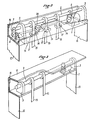
- FIG. 2 shows a schematic perspective view of the motor element of an accordion door described above, fixed inside a metal beam profiled in U 11. the base of the U being horizontal and oriented downwards .
- the beam 11 rests at each of its ends on amounts 12 and 13 of the door. It has in its horizontal part, a number of rectangular openings 14 parallel 6 its axis, intended for the passage of the lifting straps 15. Inside the beam, these rectangular openings are surrounded by a flange 17, intended to stop falling parts or any fragments of parts.
- the beam can be lined internally with insulating material 16. It receives a removable cover not shown here, also lined with insulating material. Its two ends are closed.
- a heating resistor can be placed in the isolated parallelepiped volume thus defined, preferably with a thermostat control.
- Figure 3 shows a schematic perspective view of the drive element of an accordion door described in Figure 1 fixed inside a metal beam U-shaped 11, the base of the U being vertical.
- this second arrangement of the beam two variants are possible as regards the passage of the straps. Either we take the solution adopted on the installation described in Figure 2 by making rectangular openings in the horizontal part of the beam facing down, or, - this is the case shown in Figure 3 -, we have the bearings 3 of the strap winding shaft 2 so that the straps 15 pass tangentially to the edge of the horizontal part of the beam facing downwards.
- the arrangement of the various members of the driving element in the beam is the same as previously.
- the beam can also be lined with insulating material 16, it receives a removable vertical cover (not shown in Figure 3) lined with insulating material, and is closed at both ends.
- FIG. 4 represents a schematic and partial perspective view of the driving element of an accordion door placed inside a metal beam shaped in a U shape 11 (the base of the U being vertical), which does not rest on the uprights 12, 13 of the door as in the embodiments described in Figures 2 and 3, but is fixed against said uprights, at their upper end.
- the straps 15 are horizontal over a part of their length and pass through the vertical part of the U-shaped profile 11 through rectangular openings 14.
- the reference which allows the translational movement of the straps 15 to be transmitted from the horizontal plane to the vertical plane is provided by rollers 19 - horizontal, parallel to the winding shaft 2 and freely rotating about their longitudinal axis -, over which said straps pass.
- the rollers 19 are housed in the notches 20 of a vertical plate 21 in which the ends of the axis of each of them are held.
- the plate 21 is fixed to a horizontal plate 22, the ends of which rest on the uprights 12, 13.
- a fixing is provided allowing the position of the plate 21 to be adjusted at will by a directional translation perpendicular to the winding shaft 2: the plate 22 can for example, as shown in FIG. 4, include transverse slots 23 intended to cooperate with bolts 24 welded to lugs 25 of the plate 21.
- the plate 21 is then secured to the plate 22 by nuts 26.
- the advantage of this arrangement is that it is possible, by moving the plate 21, modify the position of the flexible curtain and shift it inside the uprights 12, 13 forwards or backwards, in particular to ensure a better seal depending on whether the curtain is subjected to a dominant pressure coming from the inside or outside.
- the beam 11 can be covered with insulating material 16, it receives a removable vertical cover (not shown in the figure) itself lined with insulating material and is closed at both ends.
Abstract
Description
La présente invention a pour objet un dispositif de fixation et de protection de l'élément moteur des portes accordéon. Par élément moteur on entend le moteur, les moyens de commande du moteur, l'arbre d'enroulement des sangles, l'élément de fin de course, l'armoire électrique, etc.The present invention relates to a device for fixing and protecting the motor element of accordion doors. By motor element is meant the motor, the motor control means, the strap winding shaft, the limit switch element, the electrical cabinet, etc.
Grâce à leur conception les portes accordéon peuvent avoir une surface importante et conviennent parfaitement aux installations industrielles, entrepôts, hangards etc.Thanks to their design, accordion doors can have a large surface area and are ideal for industrial installations, warehouses, hangars, etc.
Selon un mode de réalisation connu, une porte accordéon comporte un rideau souple rigidifié à intervalles réguliers par des barres d'armature horizontales ou une série de panneaux horizontaux articulés ; des sangles de levage fixées à une extrémité à la barre d'armature inférieure du rideau souple ou à la base du panneau inférieur et à l'autre extrémité à un arbre d'enroulement dont la rotation est commandée par un moteur. Les sangles de levage passent de préférence dans des guides disposés sur certaines des barres d'armature, ou sur certaines des articulations reliant deux panneaux consécutifs. La base du panneau inférieur dans le cas d'une porte accordéon à panneaux, ou certaines des barres d'armature dont la barre inférieure dans le cas d'une porte accordéon à rideau souple, comporte un galet à chacune de leurs extrémités qui coulisse dans un guide letéral pratiqué dans les montants de la porte.According to a known embodiment, an accordion door comprises a flexible curtain stiffened at regular intervals by horizontal reinforcing bars or a series of articulated horizontal panels; lifting straps fixed at one end to the lower rebar of the flexible curtain or at the base of the lower panel and at the other end to a winding shaft whose rotation is controlled by a motor. The lifting straps preferably pass through guides arranged on some of the rebar, or on some of the joints connecting two consecutive panels. The base of the lower panel in the case of an accordion door with panels, or some of the reinforcing bars, the lower bar of which in the case of an accordion door with flexible curtain, has a roller at each of their ends which slides in a side guide in the door jambs.
Selon un mode de réalisation usuel l'arbre d'enroulement des sangles, qui surplombe la porte, pivote dans des paliers fixés à l'intérieur d'une poutre métallique profilée en U, - la base du U étant horizontale et placée vers le haut -, qui forme linteau. Le moteur provoquant la rotation de l'arbre d'enroulement des sangles est fixé le long d'un des montants de la porte à proximité du sommet de la porte. Son arbre est perpendiculaire à l'arbre d'enroulement des sangles et les deux arbres sont rendus solidaires par un renvoi d'angle comportant éventuellement une démultiplication.According to a usual embodiment, the strap winding shaft, which overhangs the door, pivots in bearings fixed inside a U-shaped metal beam, - the base of the U being horizontal and placed upwards -, which forms the lintel. The motor causing the rotation of the strap winding shaft is fixed along one of the door jambs near the top of the door. Its shaft is perpendicular to the strap winding shaft and the two shafts are made integral by a bevel gear optionally including a reduction gear.
Ce mode de réalisation usuel présente quelques inconvénients. D'une part, sur le plan de la sécurité, la disposition de la poutre profilée en U, - la base du U étant horizontale et placée vers le haut -, n'est pas pleinement satisfaisante : dans les installations industrielles il arrive fréquemment qu'une porte de ce type soit ouverte et fermée quelques centaines de fois par jour ce qui entraîne nécessairement à la longue le jeu ou la rupture de certaines pièces situées dans cette poutre, le desserrage d'écrous etc. Il peut arriver que certaines de ces pièces, des ces écrous, se désolidarisent de leur support et tombent, ce qui est susceptible de provoquer des accidents.This usual embodiment has some drawbacks. On the one hand, on in terms of security, the arrangement of the U-shaped beam, - the base of the U being horizontal and placed upwards, is not fully satisfactory: in industrial installations it often happens that a door of this type is opened and closed a few hundred times a day, which necessarily leads in the long run to the play or rupture of certain parts located in this beam, the loosening of nuts, etc. It may happen that some of these parts, these nuts, detach from their support and fall, which is likely to cause accidents.
D'autre part, la disposition du moteur le long d'un montant de la porte n'en rend pas l'entretien ni, le cas échéant, la réparation faciles. On est souvent obligé de le déposer à terre pour effectuer ces travaux de maintenance et de remise en état.On the other hand, the arrangement of the motor along a door jamb does not make maintenance or, if necessary, repair easy. We often have to put it down on the ground to carry out maintenance and repair work.
A ces deux inconvénients, il faut ajouter que, lorsque les portes accordéon sont installées dans des régions de climat rigoureux, rien n'est prévu pour protéger l'élément moteur contre les actions de la condensation et du gel : le gel de l'eau de condensation peut notamment bloquer certaines transmissions mécaniques, ce qui rend la porte inutilisable.To these two drawbacks, it should be added that, when the accordion doors are installed in regions with harsh climates, nothing is provided to protect the motor element against the actions of condensation and frost: water freezing condensation can block certain mechanical transmissions, which makes the door unusable.
La présente invention a pour objet de remédier à ces inconvénients. Elle consiste en un dispositif de fixation et de protection de l'élément moteur des portes accordéon.The object of the present invention is to remedy these drawbacks. It consists of a device for fixing and protecting the motor element of the accordion doors.
Selon une caractéristique de l'invention, l'élément moteur des portes accordéon est placé dans un coffre parallélépipède rectangle ouvrant sur l'une de ses faces longitudinales autre que la face inférieure. Ce coffre peut soit reposer sur les montants de la porte, soit être fixé contre lesdits montants, à leur extrémité supérieure.According to a characteristic of the invention, the driving element of the accordion doors is placed in a rectangular parallelepiped trunk opening on one of its longitudinal faces other than the lower face. This chest can either rest on the door jambs, or be fixed against said uprights, at their upper end.
Selon une autre caractéristique de l'invention, le coffre contenant l'élément moteur comporte une isolation thermique et une résistance chauffante, de préférence avec une commande à thermostat.According to another characteristic of the invention, the box containing the motor element comprises thermal insulation and a heating resistor, preferably with a thermostat control.
Selon encore une autre caractéristique de l'invention, le coffre contenant l'élément moteur comporte la poutre métallique profilée en U reliant les montants de la porte, la base du U étant soit horizontale et placée vers le bas, soit verticale, et un couvercle amovible pour fermer ladite poutre.According to yet another characteristic of the invention, the trunk containing the motor element comprises the U-shaped metal beam connecting the door jambs, the base of the U being either horizontal and placed downwards, or vertical, and a cover removable to close said beam.
D'autres caractéristiques et avantages de la présente invention apparaîtront mieux à la lecture de la description suivante faite en référence aux dessins annexés sur lesquels :
- La figure 1 représente le schéma de l'élément moteur d'une porte accordéon, sans son support ;
- La figure 2 représente une vue en perspective schématique de l'élément moteur d'une porte accordéon installé dans un coffre de protection situé au-dessus des montants de la porte, selon un mode de réalisation de l'invention ;
- La figure 3 représente une vue en perspective schématiqsue de l'élément moteur d'une porte accordéon installé dans un coffre de protection situé au-dessus des montants de la porté, selon un autre mode de réalisation de l'invention ;
- La figure 4 représente une vue en perspective schématique partielle de l'élément moteur d'une porte accordéon installé dans un coffre de protection situé contre les montants de la porte, selon encore un autre mode de réalisation de l'invention.
- Figure 1 shows the diagram of the motor element of an accordion door, without its support;
- FIG. 2 represents a schematic perspective view of the motor element of an accordion door installed in a protective box located above the door jambs, according to an embodiment of the invention;
- Figure 3 shows a schematic perspective view of the motor element of an accordion door installed in a protective box located above the amounts of the door, according to another embodiment of the invention;
- Figure 4 shows a partial schematic perspective view of the motor element of an accordion door installed in a protective box located against the door jambs, according to yet another embodiment of the invention.
Sur la figure 1 est représenté schématiquement l'élément moteur d'une porte accordéon, sans son support. Cet élément moteur comporte un motoréducteur 1, un arbre d'enroulement des sangles 2 pivotant dans des paliers 3, un ensemble de fin de course 4. Le motoréducteur 1, dont l'axe est parallèle à l'arbre d'enroulement des sangles 2, entraîne ce dernier par l'intermédiaire d'une chaîne de transmission 5. L'ensemble de fin de course 4, qui commande l'arrêt du moteur lorsque la porte arrive à son point d'ouverture maximale ou è son point de fermeture totale, comporte une vis 6 parallèle à l'arbre d'enroulement des sangles 2 et dont la rotation est commandée par celle dudit arbre au moyen d'une chaîne de transmission 7 ; un curseur 8 de commande des contacts de fin de course haut et bas, mobile sur la vis 6 et se déplaçant vers la droite ou vers la gauche selon le sens de rotation de l'arbre d'enroulement des sangles 2 ; deux contacts de fin de course haut et bas 9 et 10, coupant l'alimentation du motoréducteur 1 lorsque le curseur 8 fait pression sur eux ; une armoire électrique 18.In Figure 1 is shown schematically the driving element of an accordion door, without its support. This motor element comprises a geared
La figure 2 représente une vue en perspective schématique de l'élément moteur d'une porte accordéon décrit ci-dessus, fixé à l'intérieur d'une poutre métallique profilée en U 11. la base du U étant horizontale et orientée vers le bas. On reconnaît le motoréducteur 1, l'arbre d'enroulement des sangles 2 et les paliers 3 qui le supportent, l'élément de fin de course 4, les chaînes de transmission 5 et 7. La poutre 11 repose à chacune de ses extrémités sur les montants 12 et 13 de la porte. Elle comporte dans sa partie horizontale, un certain nombre d'ouvertures rectangulaires 14 parallèles 6 son axe, destinées au passage des sangles de levage 15. A l'intérieur de la poutre, ces ouvertures rectangulaires sont entourées d'un rebord 17, destiné à arrêter la chute de pièces ou de fragments de pièces éventuels. La poutre peut être tapissée intérieurement d'un matériau isolant 16. Elle reçoit un couvercle amovible non représenté ici, également tapissé de matériau isolant. Ses deux extrémités sont obturées. On peut placer dans le volume parallélépipèdique isolé ainsi défini une résistance chauffante, de préférence avec une commande à thermostat.2 shows a schematic perspective view of the motor element of an accordion door described above, fixed inside a metal beam profiled in
La figure 3 représente une vue en perspective schématique de l'élément moteur d'une porte accordéon décrit sur la figure 1 fixé à l'intérieur d'une poutre métallique profilé en U 11, la base du U étant verticale. Dans cette seconde disposition de la poutre, deux variantes sont possibles en ce qui concerne le passage des sangles. Ou bien on reprend la solution adoptée sur l'installation décrite figure 2 en pratiquant des ouvertures rectangulaires dans la partie horizontale de la poutre orientée vers le bas, ou bien, - c'est le cas représenté sur la figure 3 -, on dispose les paliers 3 de l'arbre d'enroulement des sangles 2 de telle façon que les sangles 15 passent tangentiellement au bord de la partie horizontale de la poutre orientée vers le bas. La disposition des divers organes de l'élément moteur dans la poutre est la même que précédemment. La poutre peut être également tapissée d'un matériau isolant 16, elle reçoit un capot amovible vertical ( non représenté sur la figure 3) tapissé de matériau isolant, et est obturée à ses deux extrémités.Figure 3 shows a schematic perspective view of the drive element of an accordion door described in Figure 1 fixed inside a
La figure 4 représente une vue en perspective schématique et partielle de l'élément moteur d'une porte accordéon placé à l'intérieur d'une poutre métallique profilée en U 11 (la base du U étant verticale), laquelle ne repose pas sur les montants 12, 13 de la porte comme dans les modes de réalisation décrits sur les figures 2 et 3, mais est fixée contre lesdits montants, à leur extrémité supérieure. Dans ce mode de réalisation, les sangles 15 sont horizontales sur une partie de leur longueur et traversent la partie verticale du profilé en U 11 par des ouvertures rectangulaires 14. Le renvoi qui permet la transmission du mouvement de translation des sangles 15 du plan horizontal au plan vertical est assuré par des rouleaux 19 - horizontaux, parallèles à l'arbre d'enroulement 2 et tournant librement autour de leur axe longitudinal -, sur lesquels passent lesdites sangles. Les rouleaux 19 sont logés dans les échancrures 20 d'une plaque 21 verticale dans laquelle les extrémités de l'axe de chacun d'eux sont maintenues. La plaque 21 est fixée à un plateau 22 horizontal dont les extrémités reposent sur les montants 12, 13 . Avantageusement, on prévoit une fixation permettant de régler à volonté la position de la plaque 21 par une translation de direction perpendiculaire à l'arbre d'enroulement 2 : le plateau 22 peut par exemple, comme cela est représenté sur la figure 4, comporter des fentes 23 transversales destinées à coopérer avec des boulons 24 soudés à des pattes 25 de la plaque 21. La plaque 21 est alors assujettie au plateau 22 par des écrous 26. L'intérêt de cette disposition est qu'on peut, en déplaçant la plaque 21, modifier la position du rideau souple et le décaler à l'intérieur des montants 12, 13 vers l'avant ou vers l'arrière, notamment pour assurer une meilleure étanchéité selon que le rideau est soumis à une pression dominante venant de l'intérieur ou de l'extérieur.FIG. 4 represents a schematic and partial perspective view of the driving element of an accordion door placed inside a metal beam shaped in a U shape 11 (the base of the U being vertical), which does not rest on the
La position de l'élément moteur dans la poutre 11 ainsi que l'habillement de ladite poutre sont les mêmes que ceux qui ont été décrits à propos des modes de réalisation représentés sur les figures 2 et 3 : la poutre 11 peut être tapissée d'un matériau isolant 16, elle reçoit un capot amovible vertical ( non représenté sur la figure) tapissé lui-même de matériau isolant et est obturée à ses deux extrémités.The position of the driving element in the
L'intérêt du dispositif de fixation et de protection d'une porte accordéon décrit ci-dessus est multiple.The advantage of the device for fixing and protecting an accordion door described above is multiple.
Grâce à ce dispositif, en effet :
- - les risques de chute d'une partie quelconque de l'un des organes de l'élément moteur sont totalement supprimés.
- - l'ensemble fin de course 4 est à l'abri des disfonctionnements ou dérèglements accidentels du type de ceux qui adviennent lorsqu'une partie de l'élément moteur n'est pas abritée.
- - l'entretien et les réparations éventuelles du motoréducteur ou d'un autre organe de l'élément moteur peuvent se faire sans dépose dudit organe. En outre tous les organes de l'élément moteur deviennent facilement accessibles.
- - la possibilité de fermer la poutre et de calfeutrer l'espace parallélépipèdique ainsi défini protège l'élément moteur contre les poussières, et éventuellement, moyennant l'installation d'une résistance chauffante, contre les risques de blocage dus au gel de la condensation dans les régions de climat rigoureux.
- - l'industrialisation des portes accordéon est grandement facilitée car il devient possible de constituer et de stocker des sous ensembles de l'élément moteur, lesquels pourront être fixés très rapidement, à date ultérieure, dans des poutres coupées à la longueur, selon les commandes.
- - the risk of falling of any part of one of the organs of the motor element is completely eliminated.
- - The limit switch assembly 4 is protected from accidental malfunctions or disturbances of the type that occur when a part of the motor element is not sheltered.
- - the possible maintenance and repairs of the gearmotor or of another member of the motor element can be carried out without removing said member. In addition, all the components of the drive element become easily accessible.
- - the possibility of closing the beam and caulking the parallelepipedal space thus defined protects the motor element against dust, and possibly, by means of the installation of a heating resistance, against the risks of blockage due to freezing of the condensation in regions with harsh climates.
- - the industrialization of accordion doors is greatly facilitated because it becomes possible to constitute and store subassemblies of the motor element, which can be fixed very quickly, at a later date, in beams cut to length, according to orders .
La présente invention n'est pas limitée aux exemples de réalisation qui viennent d'être décrits, elle est au contraire susceptible de modifications et de variantes qui apparaîtront à l'homme de l'art.The present invention is not limited to the exemplary embodiments which have just been described, it is on the contrary liable to modifications and variants which will appear to those skilled in the art.
Claims (12)
Priority Applications (1)
| Application Number | Priority Date | Filing Date | Title |
|---|---|---|---|
| AT85402115T ATE71428T1 (en) | 1984-11-05 | 1985-11-05 | FOLDING DOOR DRIVE MOUNTING AND PROTECTION DEVICE. |
Applications Claiming Priority (2)
| Application Number | Priority Date | Filing Date | Title |
|---|---|---|---|
| FR8416800A FR2572767B1 (en) | 1984-11-05 | 1984-11-05 | DEVICE FOR FIXING AND PROTECTING THE MOTOR ELEMENT OF ACCORDION DOORS |
| FR8416800 | 1984-11-05 |
Publications (3)
| Publication Number | Publication Date |
|---|---|
| EP0181260A2 true EP0181260A2 (en) | 1986-05-14 |
| EP0181260A3 EP0181260A3 (en) | 1987-10-28 |
| EP0181260B1 EP0181260B1 (en) | 1992-01-08 |
Family
ID=9309250
Family Applications (1)
| Application Number | Title | Priority Date | Filing Date |
|---|---|---|---|
| EP85402115A Expired - Lifetime EP0181260B1 (en) | 1984-11-05 | 1985-11-05 | Mounting and protecting device for the operating means of folding doors |
Country Status (8)
| Country | Link |
|---|---|
| US (1) | US4718471A (en) |
| EP (1) | EP0181260B1 (en) |
| JP (1) | JPS61172983A (en) |
| AT (1) | ATE71428T1 (en) |
| CA (1) | CA1269680A (en) |
| DE (1) | DE3585140D1 (en) |
| ES (1) | ES296320Y (en) |
| FR (1) | FR2572767B1 (en) |
Cited By (3)
| Publication number | Priority date | Publication date | Assignee | Title |
|---|---|---|---|---|
| WO2021146314A1 (en) * | 2020-01-13 | 2021-07-22 | Alpine Overhead Doors, Inc. | Limit position safety device for a rolling door |
| US11486195B2 (en) | 2020-01-13 | 2022-11-01 | Alpine Overhead Doors, Inc. | Limit position safety device for a rolling door |
| US11643849B2 (en) | 2020-01-13 | 2023-05-09 | Alpine Overhead Doors, Inc. | Planetary gearbox system |
Families Citing this family (28)
| Publication number | Priority date | Publication date | Assignee | Title |
|---|---|---|---|---|
| DE3765489D1 (en) * | 1986-07-23 | 1990-11-15 | Nergeco Sa | BEARING AND GEAR UNIT FOR THE WINDING SHAFT OF A ROLLING DOOR. |
| FR2603519B1 (en) * | 1986-07-29 | 1989-03-10 | Nergeco Sa | PROCESS FOR THE MANUFACTURE OF FLEXIBLE CURTAINS OF ANY SIZE AND DEVICE FOR IMPLEMENTING SAME |
| NL8802303A (en) * | 1988-09-16 | 1990-04-17 | Schoen Siegfried Joachim | ELECTRO-MOTOR-DRIVEN SUN PROTECTION. |
| US5230122A (en) * | 1991-09-23 | 1993-07-27 | Lana Robinson | Mounting device for window shades |
| US5878803A (en) * | 1993-09-08 | 1999-03-09 | Kraeutler; Bernard | Goods-handling door |
| AT419U1 (en) * | 1994-06-10 | 1995-10-25 | Sladek Leopold | CURTAIN LIFT |
| FR2747182B1 (en) * | 1996-04-05 | 1998-06-05 | Cardo Door Continental Bv | COLD ROOM SAS |
| US5908183A (en) * | 1997-07-22 | 1999-06-01 | Fury; Robert | Precision power coupling housing |
| EP0945575B8 (en) * | 1998-03-24 | 2006-11-02 | Adolf Seuster GmbH & Co. KG | Sectional lift gate |
| FR2833296B1 (en) * | 2001-12-07 | 2004-07-02 | Bernard Simon | SYSTEM FOR IMMOBILIZING A REINFORCEMENT TUBE IN A FLEXIBLE APRON OF A HANDLING DOOR |
| US20050263470A1 (en) * | 2004-05-28 | 2005-12-01 | Acabar, L.L.C. | Safety cover for a storage bay |
| FR2871839B1 (en) * | 2004-06-22 | 2006-09-15 | Nergeco Sa | SECURE DOOR WITH SECURE OPERATION |
| US8016017B2 (en) * | 2007-07-26 | 2011-09-13 | Smoke Guard, Inc. | Barrier systems and associated methods, including vapor and/or fire barrier systems |
| US8113266B2 (en) * | 2007-07-26 | 2012-02-14 | Smoke Guard, Inc. | Barrier systems and associated methods, including vapor and/or fire barrier systems |
| US20090199975A1 (en) * | 2008-02-08 | 2009-08-13 | Wei-Cheng Yeh | Electric roman shade |
| US20100243175A1 (en) * | 2009-03-30 | 2010-09-30 | Gonzales Curtis P | Barrier systems and associated methods, including vapor and/or fire barrier systems with manual egress |
| CN101525974B (en) * | 2009-04-21 | 2012-07-04 | 深圳市富诚科技发展有限公司 | Universal outer window and door shading integrated system for construction |
| US20100294437A1 (en) * | 2009-04-29 | 2010-11-25 | Gonzales Curtis P | Barrier systems with programmable acceleration profile and auto-retries for pressured egress |
| US20110088918A1 (en) * | 2009-10-19 | 2011-04-21 | Smoke Guard, Inc. | Fire-rated multilayer fabric with intumescent layer |
| US20120067528A1 (en) * | 2010-09-16 | 2012-03-22 | Mohat Nicholas C | Lead screw driven chain drive modular manually operated window shade system for an aircraft |
| CA2818655C (en) * | 2010-11-22 | 2018-07-03 | Wabash National, L.P. | Hinged bottom roller assembly and counterbalance mechanism for overhead door |
| EP2757225B1 (en) | 2011-03-11 | 2022-10-05 | Lutron Technology Company LLC | Low power radio frequency receiver |
| US9045939B2 (en) | 2011-03-11 | 2015-06-02 | Lutron Electronics Co., Inc. | Battery-powered motorized window treatment having a service position |
| US10094169B2 (en) | 2014-11-01 | 2018-10-09 | Lutron Electronics Co., Inc. | Interlocking pivotable fascia for motorized window treatment |
| ITUA20163426A1 (en) * | 2016-05-13 | 2017-11-13 | Apostoli Daniele S R L | SUPPORT STRUCTURE AND HANDLING OF A CANVAS FOR AN INDUSTRIAL DOOR |
| ITUA20163428A1 (en) * | 2016-05-13 | 2017-11-13 | Apostoli Daniele S R L | SUPPORT STRUCTURE AND HANDLING OF A CANVAS FOR AN INDUSTRIAL DOOR |
| US10864394B2 (en) * | 2016-10-31 | 2020-12-15 | Mckeon Rolling Steel Door Company, Inc. | Balancing strip collector for retractable curtain |
| US11878193B2 (en) | 2020-08-10 | 2024-01-23 | Mckeon Rolling Steel Door Co., Inc. | Self-sealing multi-segment retractable fire curtain |
Citations (9)
| Publication number | Priority date | Publication date | Assignee | Title |
|---|---|---|---|---|
| US2254150A (en) * | 1940-04-18 | 1941-08-26 | Oliver D Kingsland | Closure |
| CH454416A (en) * | 1966-01-17 | 1968-04-15 | Zanker Metallbau Gmbh | Shutter box |
| FR1577413A (en) * | 1967-07-26 | 1969-08-08 | ||
| US3487875A (en) * | 1968-01-23 | 1970-01-06 | Tudoran Tradeshop Inc | Self-operating drapery |
| FR2328098A1 (en) * | 1975-10-16 | 1977-05-13 | Weinling Joseph | Telescopic panel e.g. window blind - has overlapping inverted L:section blades with horizontal flange of reducing width on lower blades, suspended on cords |
| FR2410117A1 (en) * | 1977-11-25 | 1979-06-22 | Planet Wattohm Sa | Vertically sliding curtain door for factories - is displaced by winding vertical straps onto pulley wheels on overhead shaft driven by motor |
| DE3032003A1 (en) * | 1980-08-25 | 1982-04-22 | Berthold Haller GmbH & Co KG, 7209 Aldingen | Folding venetian blind mounting - has guide rail with strip channels and blind slot in top and bottom retaining battens |
| DE3203755A1 (en) * | 1982-02-04 | 1983-08-11 | Wilhelm Dr.-Ing. 5340 Bad Honnef Lepper | Device on roller blinds |
| FR2539181A1 (en) * | 1983-01-06 | 1984-07-13 | Kraeutler Bernard | ARTICULATED OPEN CLOSURE PANEL WITH VERTICAL DEPLOYMENT |
Family Cites Families (15)
| Publication number | Priority date | Publication date | Assignee | Title |
|---|---|---|---|---|
| FR746852A (en) * | 1933-06-07 | |||
| US2661450A (en) * | 1951-01-12 | 1953-12-01 | Overhead Door Corp | Reversible motor and control mechanism therefor |
| FR1072335A (en) * | 1951-09-27 | 1954-09-10 | Rolladenfabrik A Griesser A G | Jealousy |
| FR1155327A (en) * | 1956-08-01 | 1958-04-25 | Safety frame for blinds or roll-up closures | |
| US3249148A (en) * | 1962-06-26 | 1966-05-03 | Ronald J Zablodil | Automatic venetian blinds |
| US3308873A (en) * | 1965-04-20 | 1967-03-14 | Mallory & Co Inc P R | Venetian blind operation |
| AT298908B (en) * | 1969-05-16 | 1972-04-15 | Boehler & Co Ag Geb | DEVICE FOR LENGTH ADJUSTMENT FOR PIPING OD. DGL |
| SE386944B (en) * | 1972-08-18 | 1976-08-23 | Nordiska Maskinfilt Ab | RULLJALUSIPORT |
| US3961659A (en) * | 1974-10-10 | 1976-06-08 | Helmut Siegel | Prefabricated window unit |
| US4161647A (en) * | 1977-11-29 | 1979-07-17 | Henri Carbonnel | Electrically heated spigot for connecting an electromagnetic supplying pump to the inlet of a low pressure casting mould |
| FR2425530A1 (en) * | 1978-05-09 | 1979-12-07 | Bracq Daniel | Winding drum mounting for boxed roller blind - uses brackets extending from profiled lateral rails to support end plates including drum axle journal bearings |
| DE2929374A1 (en) * | 1979-07-20 | 1981-01-22 | Walter Paul Fa | Composite roller shutter case - has insulation mounted on bottom bent piece of sheet metal outer side |
| DE3019566A1 (en) * | 1980-05-22 | 1981-11-26 | Henkenjohann, Johann, 4837 Verl | SHUTTER |
| US4531562A (en) * | 1981-02-03 | 1985-07-30 | Chemstyle, Inc. | Interior window cover assembly for selective insulating sealable closure of a window opening |
| SE450143B (en) * | 1982-05-21 | 1987-06-09 | Ambient Energy Design | DEVICE FOR SIMILAR OPENING AND CLOSING OF GROUP OF BLINDERS |
-
1984
- 1984-11-05 FR FR8416800A patent/FR2572767B1/en not_active Expired
-
1985
- 1985-11-05 JP JP60246449A patent/JPS61172983A/en active Granted
- 1985-11-05 AT AT85402115T patent/ATE71428T1/en not_active IP Right Cessation
- 1985-11-05 DE DE8585402115T patent/DE3585140D1/en not_active Expired - Lifetime
- 1985-11-05 CA CA000494613A patent/CA1269680A/en not_active Expired - Lifetime
- 1985-11-05 EP EP85402115A patent/EP0181260B1/en not_active Expired - Lifetime
- 1985-11-06 ES ES1985296320U patent/ES296320Y/en not_active Expired
- 1985-11-06 US US06/795,610 patent/US4718471A/en not_active Expired - Lifetime
Patent Citations (9)
| Publication number | Priority date | Publication date | Assignee | Title |
|---|---|---|---|---|
| US2254150A (en) * | 1940-04-18 | 1941-08-26 | Oliver D Kingsland | Closure |
| CH454416A (en) * | 1966-01-17 | 1968-04-15 | Zanker Metallbau Gmbh | Shutter box |
| FR1577413A (en) * | 1967-07-26 | 1969-08-08 | ||
| US3487875A (en) * | 1968-01-23 | 1970-01-06 | Tudoran Tradeshop Inc | Self-operating drapery |
| FR2328098A1 (en) * | 1975-10-16 | 1977-05-13 | Weinling Joseph | Telescopic panel e.g. window blind - has overlapping inverted L:section blades with horizontal flange of reducing width on lower blades, suspended on cords |
| FR2410117A1 (en) * | 1977-11-25 | 1979-06-22 | Planet Wattohm Sa | Vertically sliding curtain door for factories - is displaced by winding vertical straps onto pulley wheels on overhead shaft driven by motor |
| DE3032003A1 (en) * | 1980-08-25 | 1982-04-22 | Berthold Haller GmbH & Co KG, 7209 Aldingen | Folding venetian blind mounting - has guide rail with strip channels and blind slot in top and bottom retaining battens |
| DE3203755A1 (en) * | 1982-02-04 | 1983-08-11 | Wilhelm Dr.-Ing. 5340 Bad Honnef Lepper | Device on roller blinds |
| FR2539181A1 (en) * | 1983-01-06 | 1984-07-13 | Kraeutler Bernard | ARTICULATED OPEN CLOSURE PANEL WITH VERTICAL DEPLOYMENT |
Cited By (4)
| Publication number | Priority date | Publication date | Assignee | Title |
|---|---|---|---|---|
| WO2021146314A1 (en) * | 2020-01-13 | 2021-07-22 | Alpine Overhead Doors, Inc. | Limit position safety device for a rolling door |
| US11486195B2 (en) | 2020-01-13 | 2022-11-01 | Alpine Overhead Doors, Inc. | Limit position safety device for a rolling door |
| US11643849B2 (en) | 2020-01-13 | 2023-05-09 | Alpine Overhead Doors, Inc. | Planetary gearbox system |
| US11725422B2 (en) | 2020-01-13 | 2023-08-15 | Alpine Overhead Doors, Inc. | Power transfer device for a rolling door operator |
Also Published As
| Publication number | Publication date |
|---|---|
| EP0181260A3 (en) | 1987-10-28 |
| ATE71428T1 (en) | 1992-01-15 |
| EP0181260B1 (en) | 1992-01-08 |
| US4718471A (en) | 1988-01-12 |
| ES296320Y (en) | 1988-02-16 |
| DE3585140D1 (en) | 1992-02-20 |
| FR2572767A1 (en) | 1986-05-09 |
| JPH0563595B2 (en) | 1993-09-10 |
| CA1269680A (en) | 1990-05-29 |
| JPS61172983A (en) | 1986-08-04 |
| FR2572767B1 (en) | 1988-04-08 |
| ES296320U (en) | 1987-08-01 |
Similar Documents
| Publication | Publication Date | Title |
|---|---|---|
| EP0181260B1 (en) | Mounting and protecting device for the operating means of folding doors | |
| EP0220096B1 (en) | Jamb for an industrial door | |
| CA1237605A (en) | Door, window or building facing panel element, made namely of two flat panes enclosing a variable volume compensated gas | |
| EP0069005B1 (en) | Lyophilizing installation having two series of racks | |
| US3474317A (en) | Safety switch cutoff control | |
| EP0501841A1 (en) | Anti-jamming device for industrial door, which consists of a flexible screen reinforced with bars | |
| EP0044799B1 (en) | Fitting for sliding windows, sliding doors or the like | |
| FR2565878A2 (en) | STACKING PLANT OF ANY SHAPED PIECES BY MEANS OF AN ORIENTABLE LANCE | |
| EP2305941A1 (en) | Device for thermal insulation of the openings of doors or windows | |
| FR2747182A1 (en) | Entry and exit chambers for cold storage room | |
| FR2831199A1 (en) | Sliding gate automised motorisation method having low voltage electric motor drive mechanism with plate held rubber rollers oscillating horizontally stopping gate movement where motor not fed. | |
| FR2508532A1 (en) | Security counter for post office - comprises box with doors at each end which cannot open simultaneously | |
| FR2520855A1 (en) | Lay-out for food cold-store - uses door mounted unitary evaporator and condenser units to conserve space and give more uniform cooling | |
| FR2514814A1 (en) | Double glazing window unit - has openings in frame which communicate air gap with both interior and exterior | |
| EP2206874B1 (en) | Arrangement comprising a window and a protection system | |
| FR2788552A1 (en) | Garage/large opening door motorised up and over mechanism having motor drive ceiling position mounted above door and door vertical/horizontal movement producing using gliding channel. | |
| BE1009782A6 (en) | Ventilator | |
| FR2844541A1 (en) | DEVICE FOR SEALING A SLIDING DOOR | |
| FR2729179A1 (en) | Motorised drive for sliding doors of refrigerated room | |
| FR2540173A1 (en) | Electromechanically operated up-and-over door | |
| EP0962236A2 (en) | Fume venting device | |
| FR2513302A1 (en) | TOTALLY TURNING ROCKER WINDOW STRUCTURE | |
| FR2693710A1 (en) | Removal system for silo stored bulk material - uses transfer screw mounted on trolley which moves along railway to access whole area of silo floor | |
| FR2800055A1 (en) | Mechanism for automatic operation of cabin doors on lifts in confined spaces, comprises motor, gearing and drive shaft at rear of cabin which propel vertically laminated sliding doors by steel cables | |
| FR2588064A1 (en) | Smoke-extraction device, especially for industrial premises |
Legal Events
| Date | Code | Title | Description |
|---|---|---|---|
| PUAI | Public reference made under article 153(3) epc to a published international application that has entered the european phase |
Free format text: ORIGINAL CODE: 0009012 |
|
| AK | Designated contracting states |
Kind code of ref document: A2 Designated state(s): AT BE CH DE FR GB IT LI LU NL SE |
|
| PUAL | Search report despatched |
Free format text: ORIGINAL CODE: 0009013 |
|
| AK | Designated contracting states |
Kind code of ref document: A3 Designated state(s): AT BE CH DE FR GB IT LI LU NL SE |
|
| 17P | Request for examination filed |
Effective date: 19871127 |
|
| 17Q | First examination report despatched |
Effective date: 19880728 |
|
| GRAA | (expected) grant |
Free format text: ORIGINAL CODE: 0009210 |
|
| AK | Designated contracting states |
Kind code of ref document: B1 Designated state(s): AT BE CH DE FR GB IT LI LU NL SE |
|
| REF | Corresponds to: |
Ref document number: 71428 Country of ref document: AT Date of ref document: 19920115 Kind code of ref document: T |
|
| REF | Corresponds to: |
Ref document number: 3585140 Country of ref document: DE Date of ref document: 19920220 |
|
| GBT | Gb: translation of ep patent filed (gb section 77(6)(a)/1977) | ||
| ITF | It: translation for a ep patent filed |
Owner name: DR. ING. A. RACHELI & C. |
|
| PLBE | No opposition filed within time limit |
Free format text: ORIGINAL CODE: 0009261 |
|
| STAA | Information on the status of an ep patent application or granted ep patent |
Free format text: STATUS: NO OPPOSITION FILED WITHIN TIME LIMIT |
|
| 26N | No opposition filed | ||
| PGFP | Annual fee paid to national office [announced via postgrant information from national office to epo] |
Ref country code: LU Payment date: 19931015 Year of fee payment: 9 |
|
| PGFP | Annual fee paid to national office [announced via postgrant information from national office to epo] |
Ref country code: SE Payment date: 19931020 Year of fee payment: 9 |
|
| PGFP | Annual fee paid to national office [announced via postgrant information from national office to epo] |
Ref country code: AT Payment date: 19931028 Year of fee payment: 9 |
|
| EPTA | Lu: last paid annual fee | ||
| PG25 | Lapsed in a contracting state [announced via postgrant information from national office to epo] |
Ref country code: LU Free format text: LAPSE BECAUSE OF NON-PAYMENT OF DUE FEES Effective date: 19941105 Ref country code: AT Effective date: 19941105 |
|
| PG25 | Lapsed in a contracting state [announced via postgrant information from national office to epo] |
Ref country code: SE Effective date: 19941106 |
|
| EAL | Se: european patent in force in sweden |
Ref document number: 85402115.1 |
|
| EUG | Se: european patent has lapsed |
Ref document number: 85402115.1 |
|
| REG | Reference to a national code |
Ref country code: FR Ref legal event code: CL |
|
| REG | Reference to a national code |
Ref country code: GB Ref legal event code: IF02 |
|
| PGFP | Annual fee paid to national office [announced via postgrant information from national office to epo] |
Ref country code: FR Payment date: 20040930 Year of fee payment: 20 |
|
| PGFP | Annual fee paid to national office [announced via postgrant information from national office to epo] |
Ref country code: NL Payment date: 20041020 Year of fee payment: 20 Ref country code: BE Payment date: 20041020 Year of fee payment: 20 |
|
| PGFP | Annual fee paid to national office [announced via postgrant information from national office to epo] |
Ref country code: GB Payment date: 20041022 Year of fee payment: 20 |
|
| PGFP | Annual fee paid to national office [announced via postgrant information from national office to epo] |
Ref country code: DE Payment date: 20041109 Year of fee payment: 20 |
|
| PGFP | Annual fee paid to national office [announced via postgrant information from national office to epo] |
Ref country code: CH Payment date: 20041112 Year of fee payment: 20 |
|
| APAH | Appeal reference modified |
Free format text: ORIGINAL CODE: EPIDOSCREFNO |
|
| PG25 | Lapsed in a contracting state [announced via postgrant information from national office to epo] |
Ref country code: GB Free format text: LAPSE BECAUSE OF EXPIRATION OF PROTECTION Effective date: 20051104 |
|
| PG25 | Lapsed in a contracting state [announced via postgrant information from national office to epo] |
Ref country code: NL Free format text: LAPSE BECAUSE OF EXPIRATION OF PROTECTION Effective date: 20051105 |
|
| BE20 | Be: patent expired |
Owner name: S.A. *NERGECO Effective date: 20051105 |
|
| REG | Reference to a national code |
Ref country code: CH Ref legal event code: PL Ref country code: GB Ref legal event code: PE20 |
|
| NLV7 | Nl: ceased due to reaching the maximum lifetime of a patent |
Effective date: 20051105 |
|
| BE20 | Be: patent expired |
Owner name: S.A. *NERGECO Effective date: 20051105 |