EP0180967A2 - Procédé pour mettre en oeuvre un onduleur afin de produire une tension basse fréquence à partir d'une tension continue et disposition de circuit applicable au dit procédé - Google Patents
Procédé pour mettre en oeuvre un onduleur afin de produire une tension basse fréquence à partir d'une tension continue et disposition de circuit applicable au dit procédé Download PDFInfo
- Publication number
- EP0180967A2 EP0180967A2 EP85114083A EP85114083A EP0180967A2 EP 0180967 A2 EP0180967 A2 EP 0180967A2 EP 85114083 A EP85114083 A EP 85114083A EP 85114083 A EP85114083 A EP 85114083A EP 0180967 A2 EP0180967 A2 EP 0180967A2
- Authority
- EP
- European Patent Office
- Prior art keywords
- voltage
- control unit
- frequency
- controlled
- reference voltage
- Prior art date
- Legal status (The legal status is an assumption and is not a legal conclusion. Google has not performed a legal analysis and makes no representation as to the accuracy of the status listed.)
- Granted
Links
Images


Classifications
-
- H—ELECTRICITY
- H02—GENERATION; CONVERSION OR DISTRIBUTION OF ELECTRIC POWER
- H02M—APPARATUS FOR CONVERSION BETWEEN AC AND AC, BETWEEN AC AND DC, OR BETWEEN DC AND DC, AND FOR USE WITH MAINS OR SIMILAR POWER SUPPLY SYSTEMS; CONVERSION OF DC OR AC INPUT POWER INTO SURGE OUTPUT POWER; CONTROL OR REGULATION THEREOF
- H02M7/00—Conversion of ac power input into dc power output; Conversion of dc power input into ac power output
- H02M7/42—Conversion of dc power input into ac power output without possibility of reversal
- H02M7/44—Conversion of dc power input into ac power output without possibility of reversal by static converters
- H02M7/48—Conversion of dc power input into ac power output without possibility of reversal by static converters using discharge tubes with control electrode or semiconductor devices with control electrode
- H02M7/4807—Conversion of dc power input into ac power output without possibility of reversal by static converters using discharge tubes with control electrode or semiconductor devices with control electrode having a high frequency intermediate AC stage
-
- H—ELECTRICITY
- H02—GENERATION; CONVERSION OR DISTRIBUTION OF ELECTRIC POWER
- H02M—APPARATUS FOR CONVERSION BETWEEN AC AND AC, BETWEEN AC AND DC, OR BETWEEN DC AND DC, AND FOR USE WITH MAINS OR SIMILAR POWER SUPPLY SYSTEMS; CONVERSION OF DC OR AC INPUT POWER INTO SURGE OUTPUT POWER; CONTROL OR REGULATION THEREOF
- H02M11/00—Power conversion systems not covered by the preceding groups
-
- H—ELECTRICITY
- H02—GENERATION; CONVERSION OR DISTRIBUTION OF ELECTRIC POWER
- H02M—APPARATUS FOR CONVERSION BETWEEN AC AND AC, BETWEEN AC AND DC, OR BETWEEN DC AND DC, AND FOR USE WITH MAINS OR SIMILAR POWER SUPPLY SYSTEMS; CONVERSION OF DC OR AC INPUT POWER INTO SURGE OUTPUT POWER; CONTROL OR REGULATION THEREOF
- H02M5/00—Conversion of ac power input into ac power output, e.g. for change of voltage, for change of frequency, for change of number of phases
- H02M5/02—Conversion of ac power input into ac power output, e.g. for change of voltage, for change of frequency, for change of number of phases without intermediate conversion into dc
- H02M5/04—Conversion of ac power input into ac power output, e.g. for change of voltage, for change of frequency, for change of number of phases without intermediate conversion into dc by static converters
- H02M5/22—Conversion of ac power input into ac power output, e.g. for change of voltage, for change of frequency, for change of number of phases without intermediate conversion into dc by static converters using discharge tubes with control electrode or semiconductor devices with control electrode
- H02M5/25—Conversion of ac power input into ac power output, e.g. for change of voltage, for change of frequency, for change of number of phases without intermediate conversion into dc by static converters using discharge tubes with control electrode or semiconductor devices with control electrode using devices of a thyratron or thyristor type requiring extinguishing means
- H02M5/27—Conversion of ac power input into ac power output, e.g. for change of voltage, for change of frequency, for change of number of phases without intermediate conversion into dc by static converters using discharge tubes with control electrode or semiconductor devices with control electrode using devices of a thyratron or thyristor type requiring extinguishing means for conversion of frequency
Definitions
- the invention relates to a method according to the preamble of claim 1. It also relates to a circuit arrangement for performing the method.
- an inverter can be used to generate a sinusoidal alternating current for a specific load from a direct voltage.
- a so-called step-wave method has become known in which a push-pull stage on the primary side drives a transformer provided with a center tap, and thus generates a square-wave voltage on the secondary side.
- the secondary winding is constructed asymmetrically, which is why the windings connected in series have different numbers of turns and thus also different output voltages point.
- an output voltage approximated to the sine can be generated, the thyristors on the secondary side being so controlled that a so-called stair curve is generated which corresponds to the sine function.
- the object of the invention is to provide a method for operating an inverter in which heavy, low-frequency components are not required.
- the method according to the invention is applied to inverters which are used in the emergency power supply of consumers who can only be operated under connection conditions of the general power supply, e.g. 220 V and 50 Hz can be used. It is also used where an uninterruptible emergency power supply e.g. is necessary for metal vapor discharge lamps that go out after a short interruption in the power supply and can only be re-ignited after a long cooling phase, or for other consumers that must be operated without interruption.
- the inverter which is operated using the method according to the invention, is used as an electronic constant voltage source. So far, such constant sine alternating voltages have generally been realized by magnetic voltage stabilizers (according to the ferroresonance principle), with the exception of the so-called rotating systems.
- the voltages, frequencies and curve shapes can be specified within wide limits by changing the reference voltage, and can also be changed during operation. It is also possible to monitor the function of the inverter with the microprocessor.
- FIG. 1 has a push-pull converter 10, the output terminals 11 and 12 of which a DC voltage coming from a battery 13 are supplied.
- This DC voltage is supplied to the primary winding of a transformer 18 by means of two transistors 14 and 15 via a part 16 and 17, the base of the two transistors 14 and 15 being controlled by a clock generator 19 which emits high-frequency control pulses.
- the secondary voltage U 1 to be taken off on the secondary side 20 of the transformer 18 is a high-frequency one Rectangular AC voltage.
- Figure 2 shows the course of this high-frequency square-wave alternating voltage in the upper figure 2a, in which the voltage U 1 is plotted over time t.
- This voltage U 1 is fed to an AC switch 21, which has, for example, two thyristor modules which are operated in anti-parallel connection.
- the AC switch is designed in such a way that it only passes positive or only negative components of the square-wave AC voltage U 1 .
- the opening times of the AC switch 21 are controlled by means of a control unit 22, a reference voltage U Ref being compared in the control unit with an output voltage U A (see below) in such a way that the AC switch only has a number of pulses corresponding to the reference voltage or the comparison voltage lets through.
- the AC switch 21 can be plus-active on the one hand and minus-active on the other, that is, where it is plus-active, it only has the positive half-waves and where it is minus- only the negative half-waves are active.
- the AC switch 21 is thus controlled by the control unit so that it passes a voltage U 2 , which is shown in Figure 2 under 2c.
- the voltage U 2 is again plotted against the time t and it can be seen that, for example, a pulse is let through at the beginning of the counting period; afterwards a pause can be seen and again the AC switch passes two positive pulses P. After a shorter pause, three pulses are passed, etc. until a total of five pulses are passed in area A. After that, the number of impulses is reduced to one again and the game that has so far run in the positive range repeats itself in the negative range. Of course it is Number of pulses depending on the voltage to be generated.
- the voltage U 2 is smoothed and filtered via an LC element with an inductor 23 and a capacitor 24, as a result of which an output voltage U 3 is applied to the output terminals of the inverters 25 and 26, which corresponds to the sine function 2d in FIG. 2. It can also be seen here that the maximum value of the voltage lies in the range A or B, that is, where most of the pulses are passed. The zero crossing is at C (see FIG. 2C), where a pulse pulse and a minus pulse are passed on the left and right.
- control unit compares the output voltage U A with the reference voltage U Ref .
- control unit can only be controlled exclusively by U Ref .
- a more optimal solution is offered by comparing U A with U Ref , insofar as it can generate an even more precise and exact sine function.
- a fluorescent lamp or any other consumer that is operated at 50 Hz can be used as the load 30.
- control unit it is also possible to design the control unit as a microprocessor. This allows the opening times of the AC switch to be controlled according to practical needs. For example, a 16-2 / 3 Hz output voltage or one with a higher frequency can be generated instead of a 50 Hz frequency without significant changes to the individual components (apart from the filter 23/24). Such a microprocessor would also be able to control the operating mode of the inverter so that errors in operation can be recognized and displayed immediately.
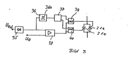
- Figure 3 shows a schematic diagram of a circuit arrangement that can be used for the control unit 22.
- a threshold switch 36 therefore derives the clock signal 36a for a flip-flop 37 with which the alternating current switch 21, which according to FIG. 3 is formed from two thyristors 21a, 21b in anti-parallel connection, that is to say the thyristors 21, 21a, 21b in 10 ms -Distance is alternately released at the respective voltage zero crossing.
- An actuating device 38 compares the target value U Ref with the actual value of the output voltage U A. If this is too small, the respective second input of two AND gates 39, 40 is set to high level and the thyristor released by the flip-flop (37) is activated.
- the high-frequency converter voltage U 1 reaches the load in the form of individual pulse packets.
- the pulse packet duration depends on the instantaneous value of the required converter output saving.
Applications Claiming Priority (2)
| Application Number | Priority Date | Filing Date | Title |
|---|---|---|---|
| DE3440926 | 1984-11-09 | ||
| DE19843440926 DE3440926A1 (de) | 1984-11-09 | 1984-11-09 | Verfahren zum betrieb eines wechselrichters zur erzeugung einer niederfrequenten wechselspannung aus einer gleichspannung, und schaltungsanordnung zur durchfuehrung des verfahrens |
Publications (3)
| Publication Number | Publication Date |
|---|---|
| EP0180967A2 true EP0180967A2 (fr) | 1986-05-14 |
| EP0180967A3 EP0180967A3 (en) | 1987-08-05 |
| EP0180967B1 EP0180967B1 (fr) | 1990-09-05 |
Family
ID=6249870
Family Applications (1)
| Application Number | Title | Priority Date | Filing Date |
|---|---|---|---|
| EP19850114083 Expired - Lifetime EP0180967B1 (fr) | 1984-11-09 | 1985-11-05 | Procédé pour mettre en oeuvre un onduleur afin de produire une tension basse fréquence à partir d'une tension continue et disposition de circuit applicable au dit procédé |
Country Status (2)
| Country | Link |
|---|---|
| EP (1) | EP0180967B1 (fr) |
| DE (1) | DE3440926A1 (fr) |
Cited By (3)
| Publication number | Priority date | Publication date | Assignee | Title |
|---|---|---|---|---|
| WO1988007316A1 (fr) * | 1987-03-17 | 1988-09-22 | Berni Ford | Activation d'elements lumineux de signalisation |
| GB2294369A (en) * | 1994-10-03 | 1996-04-24 | Mitsubishi Electric Corp | Motor controller and bidirectional dc-dc converter |
| AT413908B (de) * | 2002-08-12 | 2006-07-15 | Siemens Ag Oesterreich | Schaltwandler |
Citations (1)
| Publication number | Priority date | Publication date | Assignee | Title |
|---|---|---|---|---|
| US4281374A (en) * | 1979-05-29 | 1981-07-28 | General Electric Company | Electrical circuit for producing controlled high voltage AC output |
Family Cites Families (3)
| Publication number | Priority date | Publication date | Assignee | Title |
|---|---|---|---|---|
| US4353115A (en) * | 1980-03-28 | 1982-10-05 | Litton Systems, Inc. | Apparatus for synthesizing a sinusoidal output |
| US4339791A (en) * | 1980-09-19 | 1982-07-13 | Rockwell International Corporation | DC to low frequency inverter with pulse width modulated high frequency link |
| JPS5947981A (ja) * | 1982-07-06 | 1984-03-17 | テキサス・インスツルメンツ・インコ−ポレ−テツド | 変換装置 |
-
1984
- 1984-11-09 DE DE19843440926 patent/DE3440926A1/de not_active Withdrawn
-
1985
- 1985-11-05 EP EP19850114083 patent/EP0180967B1/fr not_active Expired - Lifetime
Patent Citations (1)
| Publication number | Priority date | Publication date | Assignee | Title |
|---|---|---|---|---|
| US4281374A (en) * | 1979-05-29 | 1981-07-28 | General Electric Company | Electrical circuit for producing controlled high voltage AC output |
Cited By (4)
| Publication number | Priority date | Publication date | Assignee | Title |
|---|---|---|---|---|
| WO1988007316A1 (fr) * | 1987-03-17 | 1988-09-22 | Berni Ford | Activation d'elements lumineux de signalisation |
| GB2294369A (en) * | 1994-10-03 | 1996-04-24 | Mitsubishi Electric Corp | Motor controller and bidirectional dc-dc converter |
| GB2294369B (en) * | 1994-10-03 | 1999-04-28 | Mitsubishi Electric Corp | Motor operation controller and isolation type bidirectional DC voltage converter |
| AT413908B (de) * | 2002-08-12 | 2006-07-15 | Siemens Ag Oesterreich | Schaltwandler |
Also Published As
| Publication number | Publication date |
|---|---|
| EP0180967A3 (en) | 1987-08-05 |
| EP0180967B1 (fr) | 1990-09-05 |
| DE3440926A1 (de) | 1986-05-15 |
Similar Documents
| Publication | Publication Date | Title |
|---|---|---|
| DE2525580C3 (fr) | ||
| DE4334592C1 (de) | Hochfrequenz-Generator | |
| DE2423718A1 (de) | Schaltungsanordnung zur erzeugung einer wechselspannung | |
| DE3613411A1 (de) | Stromversorgung fuer einen ozonerzeuger | |
| DE3241413C2 (fr) | ||
| EP0414317A2 (fr) | Dispositif d'onduleur | |
| EP0978221B1 (fr) | Circuiterie pour fonctionnement modulable d'un tube fluorescent | |
| EP0716561B1 (fr) | Appareil à rayons X comportant une unité pour l'alimentation en puissance d'un tube à rayons X | |
| EP0180967B1 (fr) | Procédé pour mettre en oeuvre un onduleur afin de produire une tension basse fréquence à partir d'une tension continue et disposition de circuit applicable au dit procédé | |
| DE3400580C2 (fr) | ||
| DE2023715B2 (de) | Anordnung zur drehzahlregelung bei einem antrieb der waeschetrommel einer waschmaschine | |
| DE2653871C2 (de) | Anordnung zur Erzeugung von Wechselspannung mit einem Asynchrongenerator | |
| DE3701805A1 (de) | Schaltungsanordnung zur stromversorgung von niederspannungsverbrauchern | |
| DE3720600A1 (de) | Stabilisierschaltung fuer schalt-spannungsversorgungsschaltung | |
| EP0496040B1 (fr) | Ballast alternatif pour lampes à décharge | |
| DE4019665C1 (fr) | ||
| CH679704A5 (fr) | ||
| DE3025421C2 (de) | Schaltungsanordnung zur Versorgung einer Gasentladungslampe aus einem Wechselstromnetz | |
| EP0491690B1 (fr) | Procede de reglage par impulsion pour un onduleur a plusieurs etages | |
| DE2714152A1 (de) | Schaltungsanordnung zur erzeugung von spannungen mit wechselnder polaritaet aus einer gleichspannung | |
| DE3933525C2 (de) | Verfahren zur Ansteuerung eines stromrichtergespeisten Drehstrommotors, der zwei galvanisch getrennte, elektrisch um 30 DEG versetzte dreiphasige Ständerwicklungen aufweist | |
| DE2646745B2 (de) | Schaltungsanordnung zur Speisung eines Gleichspannungsverbrauchers | |
| DE3709250A1 (de) | Wechselrichter zur speisung eines verbrauchers mit einer induktiven komponente | |
| EP0735659B1 (fr) | Onduleur avec génération de formes d'ondes de fréquence et tension | |
| DE2722339A1 (de) | Schaltungsanordnung zur erzeugung von spannungen mit wechselnder polaritaet aus einer gleichspannung |
Legal Events
| Date | Code | Title | Description |
|---|---|---|---|
| PUAI | Public reference made under article 153(3) epc to a published international application that has entered the european phase |
Free format text: ORIGINAL CODE: 0009012 |
|
| AK | Designated contracting states |
Kind code of ref document: A2 Designated state(s): BE FR GB IT NL |
|
| PUAL | Search report despatched |
Free format text: ORIGINAL CODE: 0009013 |
|
| AK | Designated contracting states |
Kind code of ref document: A3 Designated state(s): BE FR GB IT NL |
|
| 17P | Request for examination filed |
Effective date: 19870706 |
|
| RAP1 | Party data changed (applicant data changed or rights of an application transferred) |
Owner name: ABB CEAG LICHT- UND STROMVERSORGUNGSTECHNIK GMBH |
|
| 17Q | First examination report despatched |
Effective date: 19890721 |
|
| GRAA | (expected) grant |
Free format text: ORIGINAL CODE: 0009210 |
|
| AK | Designated contracting states |
Kind code of ref document: B1 Designated state(s): BE FR GB IT NL |
|
| ITF | It: translation for a ep patent filed |
Owner name: DE DOMINICIS & MAYER S.R.L. |
|
| ET | Fr: translation filed | ||
| GBT | Gb: translation of ep patent filed (gb section 77(6)(a)/1977) | ||
| PLBE | No opposition filed within time limit |
Free format text: ORIGINAL CODE: 0009261 |
|
| STAA | Information on the status of an ep patent application or granted ep patent |
Free format text: STATUS: NO OPPOSITION FILED WITHIN TIME LIMIT |
|
| 26N | No opposition filed | ||
| ITTA | It: last paid annual fee | ||
| PGFP | Annual fee paid to national office [announced via postgrant information from national office to epo] |
Ref country code: GB Payment date: 19941018 Year of fee payment: 10 |
|
| PGFP | Annual fee paid to national office [announced via postgrant information from national office to epo] |
Ref country code: FR Payment date: 19941109 Year of fee payment: 10 |
|
| PGFP | Annual fee paid to national office [announced via postgrant information from national office to epo] |
Ref country code: NL Payment date: 19941130 Year of fee payment: 10 Ref country code: BE Payment date: 19941130 Year of fee payment: 10 |
|
| PG25 | Lapsed in a contracting state [announced via postgrant information from national office to epo] |
Ref country code: GB Effective date: 19951105 |
|
| PG25 | Lapsed in a contracting state [announced via postgrant information from national office to epo] |
Ref country code: BE Effective date: 19951130 |
|
| BERE | Be: lapsed |
Owner name: ABB CEAG LICHT- UND STROMVERSORGUNGSTECHNIK G.M.B Effective date: 19951130 |
|
| PG25 | Lapsed in a contracting state [announced via postgrant information from national office to epo] |
Ref country code: NL Effective date: 19960601 |
|
| GBPC | Gb: european patent ceased through non-payment of renewal fee |
Effective date: 19951105 |
|
| PG25 | Lapsed in a contracting state [announced via postgrant information from national office to epo] |
Ref country code: FR Effective date: 19960731 |
|
| NLV4 | Nl: lapsed or anulled due to non-payment of the annual fee |
Effective date: 19960601 |
|
| REG | Reference to a national code |
Ref country code: FR Ref legal event code: ST |