EP0180967A2 - Process to operate an inverter producing a low-frequency AC from a DC, and circuit for the application of this process - Google Patents
Process to operate an inverter producing a low-frequency AC from a DC, and circuit for the application of this process Download PDFInfo
- Publication number
- EP0180967A2 EP0180967A2 EP85114083A EP85114083A EP0180967A2 EP 0180967 A2 EP0180967 A2 EP 0180967A2 EP 85114083 A EP85114083 A EP 85114083A EP 85114083 A EP85114083 A EP 85114083A EP 0180967 A2 EP0180967 A2 EP 0180967A2
- Authority
- EP
- European Patent Office
- Prior art keywords
- voltage
- control unit
- frequency
- controlled
- reference voltage
- Prior art date
- Legal status (The legal status is an assumption and is not a legal conclusion. Google has not performed a legal analysis and makes no representation as to the accuracy of the status listed.)
- Granted
Links
- 238000000034 method Methods 0.000 title claims abstract description 20
- 238000004804 winding Methods 0.000 claims description 6
- 239000003381 stabilizer Substances 0.000 description 3
- 238000010586 diagram Methods 0.000 description 2
- 238000005516 engineering process Methods 0.000 description 2
- 239000003990 capacitor Substances 0.000 description 1
- 238000006243 chemical reaction Methods 0.000 description 1
- 238000001816 cooling Methods 0.000 description 1
- 239000002184 metal Substances 0.000 description 1
Images


Classifications
-
- H—ELECTRICITY
- H02—GENERATION; CONVERSION OR DISTRIBUTION OF ELECTRIC POWER
- H02M—APPARATUS FOR CONVERSION BETWEEN AC AND AC, BETWEEN AC AND DC, OR BETWEEN DC AND DC, AND FOR USE WITH MAINS OR SIMILAR POWER SUPPLY SYSTEMS; CONVERSION OF DC OR AC INPUT POWER INTO SURGE OUTPUT POWER; CONTROL OR REGULATION THEREOF
- H02M7/00—Conversion of ac power input into dc power output; Conversion of dc power input into ac power output
- H02M7/42—Conversion of dc power input into ac power output without possibility of reversal
- H02M7/44—Conversion of dc power input into ac power output without possibility of reversal by static converters
- H02M7/48—Conversion of dc power input into ac power output without possibility of reversal by static converters using discharge tubes with control electrode or semiconductor devices with control electrode
- H02M7/4807—Conversion of dc power input into ac power output without possibility of reversal by static converters using discharge tubes with control electrode or semiconductor devices with control electrode having a high frequency intermediate AC stage
-
- H—ELECTRICITY
- H02—GENERATION; CONVERSION OR DISTRIBUTION OF ELECTRIC POWER
- H02M—APPARATUS FOR CONVERSION BETWEEN AC AND AC, BETWEEN AC AND DC, OR BETWEEN DC AND DC, AND FOR USE WITH MAINS OR SIMILAR POWER SUPPLY SYSTEMS; CONVERSION OF DC OR AC INPUT POWER INTO SURGE OUTPUT POWER; CONTROL OR REGULATION THEREOF
- H02M11/00—Power conversion systems not covered by the preceding groups
-
- H—ELECTRICITY
- H02—GENERATION; CONVERSION OR DISTRIBUTION OF ELECTRIC POWER
- H02M—APPARATUS FOR CONVERSION BETWEEN AC AND AC, BETWEEN AC AND DC, OR BETWEEN DC AND DC, AND FOR USE WITH MAINS OR SIMILAR POWER SUPPLY SYSTEMS; CONVERSION OF DC OR AC INPUT POWER INTO SURGE OUTPUT POWER; CONTROL OR REGULATION THEREOF
- H02M5/00—Conversion of ac power input into ac power output, e.g. for change of voltage, for change of frequency, for change of number of phases
- H02M5/02—Conversion of ac power input into ac power output, e.g. for change of voltage, for change of frequency, for change of number of phases without intermediate conversion into dc
- H02M5/04—Conversion of ac power input into ac power output, e.g. for change of voltage, for change of frequency, for change of number of phases without intermediate conversion into dc by static converters
- H02M5/22—Conversion of ac power input into ac power output, e.g. for change of voltage, for change of frequency, for change of number of phases without intermediate conversion into dc by static converters using discharge tubes with control electrode or semiconductor devices with control electrode
- H02M5/25—Conversion of ac power input into ac power output, e.g. for change of voltage, for change of frequency, for change of number of phases without intermediate conversion into dc by static converters using discharge tubes with control electrode or semiconductor devices with control electrode using devices of a thyratron or thyristor type requiring extinguishing means
- H02M5/27—Conversion of ac power input into ac power output, e.g. for change of voltage, for change of frequency, for change of number of phases without intermediate conversion into dc by static converters using discharge tubes with control electrode or semiconductor devices with control electrode using devices of a thyratron or thyristor type requiring extinguishing means for conversion of frequency
Definitions
- the invention relates to a method according to the preamble of claim 1. It also relates to a circuit arrangement for performing the method.
- an inverter can be used to generate a sinusoidal alternating current for a specific load from a direct voltage.
- a so-called step-wave method has become known in which a push-pull stage on the primary side drives a transformer provided with a center tap, and thus generates a square-wave voltage on the secondary side.
- the secondary winding is constructed asymmetrically, which is why the windings connected in series have different numbers of turns and thus also different output voltages point.
- an output voltage approximated to the sine can be generated, the thyristors on the secondary side being so controlled that a so-called stair curve is generated which corresponds to the sine function.
- the object of the invention is to provide a method for operating an inverter in which heavy, low-frequency components are not required.
- the method according to the invention is applied to inverters which are used in the emergency power supply of consumers who can only be operated under connection conditions of the general power supply, e.g. 220 V and 50 Hz can be used. It is also used where an uninterruptible emergency power supply e.g. is necessary for metal vapor discharge lamps that go out after a short interruption in the power supply and can only be re-ignited after a long cooling phase, or for other consumers that must be operated without interruption.
- the inverter which is operated using the method according to the invention, is used as an electronic constant voltage source. So far, such constant sine alternating voltages have generally been realized by magnetic voltage stabilizers (according to the ferroresonance principle), with the exception of the so-called rotating systems.
- the voltages, frequencies and curve shapes can be specified within wide limits by changing the reference voltage, and can also be changed during operation. It is also possible to monitor the function of the inverter with the microprocessor.
- FIG. 1 has a push-pull converter 10, the output terminals 11 and 12 of which a DC voltage coming from a battery 13 are supplied.
- This DC voltage is supplied to the primary winding of a transformer 18 by means of two transistors 14 and 15 via a part 16 and 17, the base of the two transistors 14 and 15 being controlled by a clock generator 19 which emits high-frequency control pulses.
- the secondary voltage U 1 to be taken off on the secondary side 20 of the transformer 18 is a high-frequency one Rectangular AC voltage.
- Figure 2 shows the course of this high-frequency square-wave alternating voltage in the upper figure 2a, in which the voltage U 1 is plotted over time t.
- This voltage U 1 is fed to an AC switch 21, which has, for example, two thyristor modules which are operated in anti-parallel connection.
- the AC switch is designed in such a way that it only passes positive or only negative components of the square-wave AC voltage U 1 .
- the opening times of the AC switch 21 are controlled by means of a control unit 22, a reference voltage U Ref being compared in the control unit with an output voltage U A (see below) in such a way that the AC switch only has a number of pulses corresponding to the reference voltage or the comparison voltage lets through.
- the AC switch 21 can be plus-active on the one hand and minus-active on the other, that is, where it is plus-active, it only has the positive half-waves and where it is minus- only the negative half-waves are active.
- the AC switch 21 is thus controlled by the control unit so that it passes a voltage U 2 , which is shown in Figure 2 under 2c.
- the voltage U 2 is again plotted against the time t and it can be seen that, for example, a pulse is let through at the beginning of the counting period; afterwards a pause can be seen and again the AC switch passes two positive pulses P. After a shorter pause, three pulses are passed, etc. until a total of five pulses are passed in area A. After that, the number of impulses is reduced to one again and the game that has so far run in the positive range repeats itself in the negative range. Of course it is Number of pulses depending on the voltage to be generated.
- the voltage U 2 is smoothed and filtered via an LC element with an inductor 23 and a capacitor 24, as a result of which an output voltage U 3 is applied to the output terminals of the inverters 25 and 26, which corresponds to the sine function 2d in FIG. 2. It can also be seen here that the maximum value of the voltage lies in the range A or B, that is, where most of the pulses are passed. The zero crossing is at C (see FIG. 2C), where a pulse pulse and a minus pulse are passed on the left and right.
- control unit compares the output voltage U A with the reference voltage U Ref .
- control unit can only be controlled exclusively by U Ref .
- a more optimal solution is offered by comparing U A with U Ref , insofar as it can generate an even more precise and exact sine function.
- a fluorescent lamp or any other consumer that is operated at 50 Hz can be used as the load 30.
- control unit it is also possible to design the control unit as a microprocessor. This allows the opening times of the AC switch to be controlled according to practical needs. For example, a 16-2 / 3 Hz output voltage or one with a higher frequency can be generated instead of a 50 Hz frequency without significant changes to the individual components (apart from the filter 23/24). Such a microprocessor would also be able to control the operating mode of the inverter so that errors in operation can be recognized and displayed immediately.
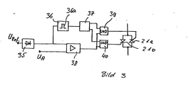
- Figure 3 shows a schematic diagram of a circuit arrangement that can be used for the control unit 22.
- a threshold switch 36 therefore derives the clock signal 36a for a flip-flop 37 with which the alternating current switch 21, which according to FIG. 3 is formed from two thyristors 21a, 21b in anti-parallel connection, that is to say the thyristors 21, 21a, 21b in 10 ms -Distance is alternately released at the respective voltage zero crossing.
- An actuating device 38 compares the target value U Ref with the actual value of the output voltage U A. If this is too small, the respective second input of two AND gates 39, 40 is set to high level and the thyristor released by the flip-flop (37) is activated.
- the high-frequency converter voltage U 1 reaches the load in the form of individual pulse packets.
- the pulse packet duration depends on the instantaneous value of the required converter output saving.
Landscapes
- Engineering & Computer Science (AREA)
- Power Engineering (AREA)
- Inverter Devices (AREA)
Abstract
Description
Die Erfindung betrifft ein Verfahren nach dem Oberbegriff des Anspruchs 1. Sie betrifft ferner eine Schaltungsanordnung zur Durchführung des Verfahrens.The invention relates to a method according to the preamble of
Es gibt eine Reihe von Verfahren, mit denen mittels eines Wechselrichters aus einer Gleichspannung ein Sinus-Wechselstrom für eine bestimmte Last erzeugt wird. Beispielsweise ist ein sogenanntes Step-Wave-Verfahren bekannt geworden, bei der auf der Primärseite eine Gegentaktstufe einen mit einer Mittelanzapfung versehenen Transformator ansteuert, und somit auf der Sekundärseite eine Rechteckspannung erzeugt. Dabei ist die Sekundärwicklung unsymmetrisch aufgebaut, weswegen die in Reihe geschalteten Wicklungen unterschiedliche Windungszahlen und damit auch unterschiedliche Ausgangsspannungen auf weisen. Mit Hilfe dieser beiden Spannungen läßt sich eine dem Sinus angenäherte Ausgangsspannung erzeugen, wobei die Thyristoren auf der Sekundärseite so anzusteuern sind, daß eine sogenannte Treppenkurve erzeugt wird, die der Sinusfuktion entspricht. Um eine möglichst gleichmäßige Sinuskurve zu erhalten, müßte die Anzahl der Stufen erhöht werden, was aber bedeutet, daß mehr als zwei unterschiedliche Rechteckspannungen erzeugt werden müssen. Dadurch wird der Aufwand für die Steuerung recht hoch. Es ist weiterhin bekannt, eine SinusWechselspannung durch eine Pulsdauermodulation zu erhalten. Bei dieser Modulationsart wird die Impulsdauer verändert, wobei die Pulsamplitude, die Pulsfrequenz und die Phase unverändert bleiben und nur das Tastverhältnis sich ändert. Bei dieser Anordnung wird die Pulsdauer auf der Primärseite des Leistungstransformators moduliert, um auf der Sekundärseite eine entsprechend gesteuerte sinusförmig Spannung zu erhalten.There are a number of methods by means of which an inverter can be used to generate a sinusoidal alternating current for a specific load from a direct voltage. For example, a so-called step-wave method has become known in which a push-pull stage on the primary side drives a transformer provided with a center tap, and thus generates a square-wave voltage on the secondary side. The secondary winding is constructed asymmetrically, which is why the windings connected in series have different numbers of turns and thus also different output voltages point. With the help of these two voltages, an output voltage approximated to the sine can be generated, the thyristors on the secondary side being so controlled that a so-called stair curve is generated which corresponds to the sine function. In order to obtain a sinus curve that is as uniform as possible, the number of stages would have to be increased, but this means that more than two different square-wave voltages must be generated. As a result, the effort for the control is quite high. It is also known to obtain an alternating sine voltage by means of pulse duration modulation. With this type of modulation the pulse duration is changed, whereby the pulse amplitude, the pulse frequency and the phase remain unchanged and only the pulse duty factor changes. With this arrangement, the pulse duration is modulated on the primary side of the power transformer in order to obtain a correspondingly controlled sinusoidal voltage on the secondary side.
Da bei diesen bekannten Verfahren die Sinusfunktion auf der Primärseite des Leistungstransformators erzeugt wird, benötigt man schwere und voluminöse Bauteile der Niederfrequenztechnik, entweder zur direkten Umwandlung wie beim Gegentaktwandler, oder aber auch bei Schaltungen, die zunächst die Gleichspannung in eine höherfrequente Wechselspannung umwandeln, wobei dann zusätzlich noch zur Aussiebung der Grundwelle ebenfalls entsprechend niederfrequente Bauelemente erforderlich werden.Since in these known methods the sine function is generated on the primary side of the power transformer, heavy and voluminous components of low-frequency technology are required, either for direct conversion as in the push-pull converter, or also for circuits which first convert the DC voltage into a higher-frequency AC voltage, then in addition to the sifting out of the fundamental wave, correspondingly low-frequency components may also be required.
Aufgabe der Erfindung ist es, ein Verfahren zum Betrieb eines Wechselrichters anzugeben, bei dem schwere niederfrequente Bauelemente nicht erforderlich sind.The object of the invention is to provide a method for operating an inverter in which heavy, low-frequency components are not required.
Diese Aufgabe wird erfindungsgemäß gelöst durch die kennzeichnnenden Merkmale des Anspruchs 1.This object is achieved according to the invention by the characterizing features of
Die Schaltungsanordnung bei der erfindungsgemäß das Verfahren durchgeführt werden kann, ist den Ansprüchen 5 und 6 zu entnehmen.The circuit arrangement in which the method can be carried out according to the invention can be found in claims 5 and 6.
Weitere vorteilhafte Ausgestaltungen der Erfindung sind den weiteren Unteransprüchen zu entnehmen.Further advantageous embodiments of the invention can be found in the further subclaims.
Das erfindungsgemäße Verfahren wird bei Wechselrichtern angewandt, die in der Notstromversorgung von Verbrauchern, die nur mit Anschlußbedingungen der allgemeinen Stromversorgung betrieben werden können, z.B. 220 V und 50 Hz, eingesetzt werden. Es wird ferner dort angewandt, wo eine unterbrechungsfreie Notstromversorgung z.B. für Metalldampfentladungslampen erforderlich wird, die nach kurzer Netzunterbrechung verlöschen und erst nach einer längeren Abkühlungsphase wiedergezündet werden können, oder für andere Verbraucher, die unterbrechungsfrei betrieben werden müssen. Darüberhinaus wird der Wechselrichter, der mit dem erfindungsgemäßen Verfahren betrieben wird, als elektronische Konstantspannungsquelle verwendet. Bisher wurden derartige konstante Sinuswechselspannungen im allgemeinen durch magnetische Spannungskonstanthalter (nach dem Ferroresonanzprinzip) realisiert, wobei als Ausnahme die sogenannten rotierenden Systeme anzusehen waren. Bei derartigen Spannungskonstanthaltern waren zwar wenig Bauteile erforderlich und die Zuverlässigkeit war auch groß; eine konstante Ausgangsspannung aber konnte nur bei konstanter Eingangsfrequenz und sinusförmiger Eingangsspannung erzeugt werden. Demgemäß waren bei derartigen Spannungskonstanthaltern im Gegensatz zu der erfindungsgemäßen Ausführung große Volumina und schwere Bauelemente wegen der 50-Hz-Technik erforderlich.The method according to the invention is applied to inverters which are used in the emergency power supply of consumers who can only be operated under connection conditions of the general power supply, e.g. 220 V and 50 Hz can be used. It is also used where an uninterruptible emergency power supply e.g. is necessary for metal vapor discharge lamps that go out after a short interruption in the power supply and can only be re-ignited after a long cooling phase, or for other consumers that must be operated without interruption. In addition, the inverter, which is operated using the method according to the invention, is used as an electronic constant voltage source. So far, such constant sine alternating voltages have generally been realized by magnetic voltage stabilizers (according to the ferroresonance principle), with the exception of the so-called rotating systems. With such voltage stabilizers, few components were required and the reliability was also great; a constant output voltage could only be generated with a constant input frequency and sinusoidal input voltage. Accordingly, in contrast to the embodiment according to the invention, large volumes and heavy components were required for such voltage stabilizers because of the 50 Hz technology.
Wenn darüberhinaus bei der erfindungsgemäßen Lösung für die Regelungsaufgaben ein Mikroprozessor eingesetzt wird, so lassen sich durch Änderung der Referenzspannung die Spannungen, Frequenzen und Kurvenformen in weiten Grenzen vorgeben, und auch während des Betriebs ändern. Weiterhin ist es möglich, die Funktion des Wechselrichters mit dem Mikroprozessor zu überwachen.If, in addition, a microprocessor is used for the control tasks in the solution according to the invention, the voltages, frequencies and curve shapes can be specified within wide limits by changing the reference voltage, and can also be changed during operation. It is also possible to monitor the function of the inverter with the microprocessor.
Anhand der Zeichnung in der ein Ausführungsbeispiel der Erfindung dargestellt ist soll die Erfindung näher er- . läutert und beschrieben werden.On the basis of the drawing in which an embodiment of the invention is shown, the invention is intended to be more closely. are explained and described.
Es zeigt:
- Fig. 1 eine Schaltungsanordnung, in schematischer Darstellung, anhand der das erfindungsgemäße Verfahren erläutert werden soll,
- Fig. 2 Spannurigs- ,Zeitdiagramme der unterschiedlichen Komponenten, und
- Fig. 3 eine Schaltungsanordnung für die Steuereinheit.
- 1 is a circuit arrangement, in a schematic representation, on the basis of which the inventive method is to be explained,
- Fig. 2 Spannurigs, time diagrams of the different components, and
- Fig. 3 shows a circuit arrangement for the control unit.
Der Wechselrichter gemäß Fig. 1 besitzt einen Gegentaktwandler 10, dessen Ausgangsklemmen 11 und 12 von einer Batterie 13 herkommende Gleichspannung zugeführt wird. Diese Gleichspannung wird mittels zweier Transistoren 14 und 15 über einen Teil 16 bzw. 17 der Primärwicklung eines Transformators 18 zugeführt, wobei die Basis der beiden Transistoren 14 und 15 von einem Taktgeber 19 angesteuert wird, der hochfrequente Steuerimpulse abgibt. Die auf der Sekundärseite 20 des Transformators 18 abzunehmende Sekundärspannung U1 ist eine hochfrequente Rechteck-Wechselspannung. In Bild 2 erkennt man den Verlauf dieser hochfrequenten Rechteckwechselspannung im oberen Bild 2a, in dem über der Zeit t die Spannung U1 aufgetragen ist. Diese Spannung U1 wird einem Wechselstromschalter 21 zugeführt, der beispielsweise zwei Thyristormodule aufweist, die in Antiparallelschaltung betrieben werden. Der Wechselstromschalter ist dabei so ausgelegt, daß er entweder nur positive oder nur negative Anteile der Rechteck-Wechselspannung U1 durchläßt. Mittels einer Steuereinheit 22 werden die Öffnungszeiten des Wechselstromschalters 21 gesteuert, wobei in der Steuereinheit eine Referenzspannung URef mit einer Ausgangsspannung UA (vergleiche weiter unten) verglichen wird, dergestalt, daß der Wechselstromschalter nur eine der Referenzspannung bzw. der Vergleichsspannung entsprechende Anzahl von Impulsen durchläßt. Es wird in Bild 2, bei 2b angedeutet, daß der Wechselstromschalter 21 einmal plus-aktiv und zum anderen minus-aktiv sein kann, d.h., daß er dort, wo er plus-aktiv ist, lediglich die positiven Halbwellen und dort wo er minus-aktiv ist lediglich die negativen Halbwellen durchläßt.1 has a push-
Der Wechselstromschalter 21 wird also von der Steuereinheit so angesteuert, daß er eine Spannung U2 durchläßt, die in Bild 2 unter 2c dargestellt ist. Die Spannung U2 ist wieder über der Zeit t aufgetragen und man erkennt, daß z.B. zu Beginn der Zähldauer ein Impuls durchgelassen wird; danach ist eine Pause zu sehen und wiederum danach läßt der Wechselstromschalter zwei positive Impulse P durch. Nach einer kürzeren Pause werden drei Impulse durchgelassen, usw bis im Bereich A insgesamt fünf Impulse durchgelassen werden. Danach reduziert sich die Anzahl der Impulse wieder auf eins und das Spiel, das bis jetzt im positiven Bereich abgelaufen ist, wiederholt sich im negativen Bereich. Natürlich ist die Zahl der Impulse von d zu erzeugenden Spannung abhängig. Im Bild 2c soll nur angedeutet werden, daß sich die Zahl der durchgelassenen Impulse ändern muß, von Beginn des Nulldurchgangs wenig Impulse, bei maximaler Amplitude bei A viele Impulse, eben entsprechend der zu erzeugenden sinusförmigen Spannungen. Eine Einschränkung der Erfindung soll diese Darstellung nicht bedeuten.The
Die Spannung U2 wird geglättet und gefiltert über ein L-C-Glied mit einer Induktivität 23 und einer Kapazität 24, wodurch an den Ausgangsklemmen des Wechselrichters 25 und 26 eine Ausgangsspannung U3 anliegt, die der Sinusfunktion 2d in Fig. 2 entspricht. Man erkennt hierbei auch, daß der Maximalwert der Spannung im Bereich A bzw. B liegt, also dort, wo die meisten Impulse durchgelassen werden. Der Nulldurchgang ist bei C (siehe 2C), wo links und rechts jeweils ein Puls- bzw. ein Minusimpuls durchgelassen wird.The voltage U 2 is smoothed and filtered via an LC element with an
Es ist vorhin angedeutet worden, daß die Steuereinheit die Ausgangsspannung UA mit der Referenzspannung URef vergleicht. Natürlich kann die Steuereinheit auch nur ausschließlich durch URef gesteuert werden. Eine optimalere Lösung bietet aber der Vergleich von UA mit URef, insoweit, als dadurch eine noch genauere und exaktere Sinusfunktion erzeugt werden kann.It has already been indicated that the control unit compares the output voltage U A with the reference voltage U Ref . Of course, the control unit can only be controlled exclusively by U Ref . A more optimal solution is offered by comparing U A with U Ref , insofar as it can generate an even more precise and exact sine function.
Eine zusätzliche Verbesserung des Regelverhaltens des Wechselrichters bringt folgende Maßnahme:
- Man nimmt von der Steuereinheit ein Steuersignal ab und führt dieses über eine
Leitung 27 einemPulslängenmodulator 28 zu, der denTaktgeber 19 in Abhängigkeit von der Regelabweichüng in seinen Schaltzeiten steuert. Nicht beeinflußt wird der Taktgeber in seiner Taktfre quenz. Die Frequenz mit der der Transformator betrieben wird, ist die gleiche, lediglich die Pulslänge wird verändert, was insbesondere im Bereich des Nulldurchgangs der Sinusspannung von wesentlichem Vorteil ist. Dadurch wird nämlich vermieden, daß der Last im Bereich der Nahtdurchgänge zuviel Energie zugeführt wird, was dazu führen kann, daß die Sinusfunktion keine echte Sinusfunktion ist, sondern eine solche mit Zacken im Bereich der Nulldurchgänge.
- A control signal is taken from the control unit and fed via a
line 27 to apulse length modulator 28 which controls theclock generator 19 in its switching times as a function of the control deviation. The clock is not affected in its clock frequency quenz. The frequency with which the transformer is operated is the same, only the pulse length is changed, which is of particular advantage in the area of the zero crossing of the sine voltage. This prevents namely that too much energy is supplied to the load in the area of the seam crossings, which can lead to the fact that the sine function is not a real sine function, but one with jags in the area of the zero crossings.
Als Last 30 kann beispielsweise eine Leuchtstofflampe oder irgendein anderer Verbraucher verwendet werden, der mit 50 Hz betrieben wird.For example, a fluorescent lamp or any other consumer that is operated at 50 Hz can be used as the
Es besteht auch die Möglichkeit, die Steuereinheit als einen Mikroprozessor auszubilden. Dadurch können die Öffnungszeiten des Wechselstromschalters nach den Bedürfnissen der Praxis gesteuert werden. Beispielsweise kann anstatt einer 50-Hz-Frequenz ohne wesentliche Änderungen der einzelnen Komponenten (bis auf das Filter 23/24) eine 16-2/3-Hz-Ausgangsspannung oder eine mit höherer Frequenz erzeugt werden. Ein derartiger Mikroprozessor wäre darüberhinaus auch in der Lage, die Betriebsart des Wechselrichters zu steuern, so daß Fehler im Betrieb sofort erkannt und angezeigt werden können.It is also possible to design the control unit as a microprocessor. This allows the opening times of the AC switch to be controlled according to practical needs. For example, a 16-2 / 3 Hz output voltage or one with a higher frequency can be generated instead of a 50 Hz frequency without significant changes to the individual components (apart from the
Dadurch, daß über den Transformator 18 nur Hochfrequenzimpulse übertragen werden, können kleine und leichte Bauteile verwendet werden, Bauteile, die für Hochfrequenz geeignet sind und niederfrequente Bauelemente können vermieden werden. Dadurch wird die gesamte Schaltungsanordnung bzw. der gesamte Wechselrichter erheblich einfacher in seiner Ausgestaltung.Because only high-frequency pulses are transmitted via the
In Bild 3 ist eine Prinzipskizze einer Schaltungsanordnung dargestellt, wie die für die Steuereinheit 22 verwendet werden kann.Figure 3 shows a schematic diagram of a circuit arrangement that can be used for the
Als Sollwert URef wird bei Verwendung der Schaltungsanordnung für eine mit Sinuswechselspannung zu betreibende Last ebenfalls eine Sinuswechselspannung benötigt, die über eine Gleichrichterbrücke 35 in eine Sinushalbwellenspannung umgewandelt wird. Ein Schwellwertschalter 36 leitet darazs das Taktsignal 36a für ein Flip-Flop 37 ab, mit dem der Wechseltsromschalter 21, der gemäß Fig. 3 aus zwei Thyristoren 21a, 21b in Antiparallelschaltung gebildet ist, d.h. also die Thyristoren 21, 21a, 21b im 10 ms-Abstand beim jeweiligen Spannungsnulldurchgang abwechselnd freigegeben wird bzw. werden. Eine Stelleinrichtung 38 vergleicht den Sollwert URef mit dem Istwert der Ausgangsspannung UA. Ist diese zu klein, so wird der jeweils zweite Eingang zweider UND-Gatter 39, 40 auf High-Pegel gelegt und der durch das Flip-Flop (37) freigegebene Thyristor wird angesteuert.When using the circuit arrangement for a load to be operated with sine alternating voltage, a sine alternating voltage is also required as setpoint value U Ref , which is converted into a sine half-wave voltage via a
Dadurch gelangen die positiven oder negativen Pulse der Wandlerausgangsspannung U1 an die Last 30 und zwar solange, bis die Ausgangsspannung den Sollwert erreicht. Von der Stelleinrichtung 38 wird dann jeweils ein UND-Gatter-Eingang auf Null gezogen und somit die Ansteuerung der Thyristoren 21a, 21b unterbunden.As a result, the positive or negative pulses of the converter output voltage U 1 reach the
Durch dieses Steuerverfahren gelangt die hochfrequente Wandlerspannung U1 in Form von einzelnen Pulspaketen an die Last. Die Pulspaketdauer ist dabei abhängig von dem Augenblickswert der erforderlichen Wandlerausgangssparnung.Through this control method, the high-frequency converter voltage U 1 reaches the load in the form of individual pulse packets. The pulse packet duration depends on the instantaneous value of the required converter output saving.
Claims (6)
Applications Claiming Priority (2)
| Application Number | Priority Date | Filing Date | Title |
|---|---|---|---|
| DE19843440926 DE3440926A1 (en) | 1984-11-09 | 1984-11-09 | METHOD FOR OPERATING AN INVERTER TO GENERATE A LOW-FREQUENCY AC VOLTAGE FROM A DC VOLTAGE, AND CIRCUIT FOR IMPLEMENTING THE METHOD |
| DE3440926 | 1984-11-09 |
Publications (3)
| Publication Number | Publication Date |
|---|---|
| EP0180967A2 true EP0180967A2 (en) | 1986-05-14 |
| EP0180967A3 EP0180967A3 (en) | 1987-08-05 |
| EP0180967B1 EP0180967B1 (en) | 1990-09-05 |
Family
ID=6249870
Family Applications (1)
| Application Number | Title | Priority Date | Filing Date |
|---|---|---|---|
| EP19850114083 Expired - Lifetime EP0180967B1 (en) | 1984-11-09 | 1985-11-05 | Process to operate an inverter producing a low-frequency ac from a dc, and circuit for the application of this process |
Country Status (2)
| Country | Link |
|---|---|
| EP (1) | EP0180967B1 (en) |
| DE (1) | DE3440926A1 (en) |
Cited By (3)
| Publication number | Priority date | Publication date | Assignee | Title |
|---|---|---|---|---|
| WO1988007316A1 (en) * | 1987-03-17 | 1988-09-22 | Berni Ford | Activating lighted signs |
| GB2294369A (en) * | 1994-10-03 | 1996-04-24 | Mitsubishi Electric Corp | Motor controller and bidirectional dc-dc converter |
| AT413908B (en) * | 2002-08-12 | 2006-07-15 | Siemens Ag Oesterreich | SWITCHING REGULATOR |
Citations (1)
| Publication number | Priority date | Publication date | Assignee | Title |
|---|---|---|---|---|
| US4281374A (en) * | 1979-05-29 | 1981-07-28 | General Electric Company | Electrical circuit for producing controlled high voltage AC output |
Family Cites Families (3)
| Publication number | Priority date | Publication date | Assignee | Title |
|---|---|---|---|---|
| US4353115A (en) * | 1980-03-28 | 1982-10-05 | Litton Systems, Inc. | Apparatus for synthesizing a sinusoidal output |
| US4339791A (en) * | 1980-09-19 | 1982-07-13 | Rockwell International Corporation | DC to low frequency inverter with pulse width modulated high frequency link |
| JPS5947981A (en) * | 1982-07-06 | 1984-03-17 | テキサス・インスツルメンツ・インコ−ポレ−テツド | Converter |
-
1984
- 1984-11-09 DE DE19843440926 patent/DE3440926A1/en not_active Withdrawn
-
1985
- 1985-11-05 EP EP19850114083 patent/EP0180967B1/en not_active Expired - Lifetime
Patent Citations (1)
| Publication number | Priority date | Publication date | Assignee | Title |
|---|---|---|---|---|
| US4281374A (en) * | 1979-05-29 | 1981-07-28 | General Electric Company | Electrical circuit for producing controlled high voltage AC output |
Cited By (4)
| Publication number | Priority date | Publication date | Assignee | Title |
|---|---|---|---|---|
| WO1988007316A1 (en) * | 1987-03-17 | 1988-09-22 | Berni Ford | Activating lighted signs |
| GB2294369A (en) * | 1994-10-03 | 1996-04-24 | Mitsubishi Electric Corp | Motor controller and bidirectional dc-dc converter |
| GB2294369B (en) * | 1994-10-03 | 1999-04-28 | Mitsubishi Electric Corp | Motor operation controller and isolation type bidirectional DC voltage converter |
| AT413908B (en) * | 2002-08-12 | 2006-07-15 | Siemens Ag Oesterreich | SWITCHING REGULATOR |
Also Published As
| Publication number | Publication date |
|---|---|
| EP0180967B1 (en) | 1990-09-05 |
| EP0180967A3 (en) | 1987-08-05 |
| DE3440926A1 (en) | 1986-05-15 |
Similar Documents
| Publication | Publication Date | Title |
|---|---|---|
| DE4334592C1 (en) | High frequency generator | |
| DE2423718A1 (en) | CIRCUIT ARRANGEMENT FOR GENERATING AN AC VOLTAGE | |
| DE3613411A1 (en) | POWER SUPPLY FOR AN OZONE GENERATOR | |
| DE3241413C2 (en) | ||
| EP0978221B1 (en) | Circuitry for dimming a fluorescent lamp | |
| EP0716561B1 (en) | X-ray apparatus with a power supply unit for an x-ray tube | |
| DE69410775T2 (en) | Electronic ballast for discharge lamps with a resonant circuit to limit the form factor and to improve the power factor | |
| EP0180967B1 (en) | Process to operate an inverter producing a low-frequency ac from a dc, and circuit for the application of this process | |
| DE3400580C2 (en) | ||
| DE2023715B2 (en) | ARRANGEMENT FOR THE SPEED CONTROL IN A DRIVE OF THE DRUM DRUM OF A WASHING MACHINE | |
| DE2653871C2 (en) | Arrangement for generating alternating voltage with an asynchronous generator | |
| DE3136676C2 (en) | Control circuit for an electromagnetic cooking device | |
| DE3701805A1 (en) | Circuit arrangement for supplying electrical power to low-voltage loads | |
| DE3720600A1 (en) | STABILIZER CIRCUIT FOR SWITCHING POWER SUPPLY CIRCUIT | |
| EP0496040B1 (en) | AC Ballast for discharge lamps | |
| DE4019665C1 (en) | ||
| CH679704A5 (en) | ||
| DE3025421C2 (en) | Circuit arrangement for supplying a gas discharge lamp from an alternating current network | |
| EP0491690B1 (en) | Process for control of a multi-stage pulse converter | |
| DE2714152A1 (en) | Static inverter generating pulses of alternate polarity - uses switched power transistors feeding pulse-shaping integrator | |
| DE3933525C2 (en) | Method for controlling a converter-fed three-phase motor which has two galvanically separated, three-phase stator windings which are electrically offset by 30 ° | |
| DE2646745B2 (en) | Circuit arrangement for feeding a DC voltage consumer | |
| DE3709250A1 (en) | Invertor for supplying a load with an inductive component | |
| DE9408734U1 (en) | High-voltage supply circuit for a gas discharge lamp | |
| EP0735659B1 (en) | Inverter with frequency and voltage waveform generation |
Legal Events
| Date | Code | Title | Description |
|---|---|---|---|
| PUAI | Public reference made under article 153(3) epc to a published international application that has entered the european phase |
Free format text: ORIGINAL CODE: 0009012 |
|
| AK | Designated contracting states |
Kind code of ref document: A2 Designated state(s): BE FR GB IT NL |
|
| PUAL | Search report despatched |
Free format text: ORIGINAL CODE: 0009013 |
|
| AK | Designated contracting states |
Kind code of ref document: A3 Designated state(s): BE FR GB IT NL |
|
| 17P | Request for examination filed |
Effective date: 19870706 |
|
| RAP1 | Party data changed (applicant data changed or rights of an application transferred) |
Owner name: ABB CEAG LICHT- UND STROMVERSORGUNGSTECHNIK GMBH |
|
| 17Q | First examination report despatched |
Effective date: 19890721 |
|
| GRAA | (expected) grant |
Free format text: ORIGINAL CODE: 0009210 |
|
| AK | Designated contracting states |
Kind code of ref document: B1 Designated state(s): BE FR GB IT NL |
|
| ITF | It: translation for a ep patent filed | ||
| ET | Fr: translation filed | ||
| GBT | Gb: translation of ep patent filed (gb section 77(6)(a)/1977) | ||
| PLBE | No opposition filed within time limit |
Free format text: ORIGINAL CODE: 0009261 |
|
| STAA | Information on the status of an ep patent application or granted ep patent |
Free format text: STATUS: NO OPPOSITION FILED WITHIN TIME LIMIT |
|
| 26N | No opposition filed | ||
| ITTA | It: last paid annual fee | ||
| PGFP | Annual fee paid to national office [announced via postgrant information from national office to epo] |
Ref country code: GB Payment date: 19941018 Year of fee payment: 10 |
|
| PGFP | Annual fee paid to national office [announced via postgrant information from national office to epo] |
Ref country code: FR Payment date: 19941109 Year of fee payment: 10 |
|
| PGFP | Annual fee paid to national office [announced via postgrant information from national office to epo] |
Ref country code: NL Payment date: 19941130 Year of fee payment: 10 Ref country code: BE Payment date: 19941130 Year of fee payment: 10 |
|
| PG25 | Lapsed in a contracting state [announced via postgrant information from national office to epo] |
Ref country code: GB Effective date: 19951105 |
|
| PG25 | Lapsed in a contracting state [announced via postgrant information from national office to epo] |
Ref country code: BE Effective date: 19951130 |
|
| BERE | Be: lapsed |
Owner name: ABB CEAG LICHT- UND STROMVERSORGUNGSTECHNIK G.M.B Effective date: 19951130 |
|
| PG25 | Lapsed in a contracting state [announced via postgrant information from national office to epo] |
Ref country code: NL Effective date: 19960601 |
|
| GBPC | Gb: european patent ceased through non-payment of renewal fee |
Effective date: 19951105 |
|
| PG25 | Lapsed in a contracting state [announced via postgrant information from national office to epo] |
Ref country code: FR Effective date: 19960731 |
|
| NLV4 | Nl: lapsed or anulled due to non-payment of the annual fee |
Effective date: 19960601 |
|
| REG | Reference to a national code |
Ref country code: FR Ref legal event code: ST |