EP0180378A2 - Kontaktbürstenaufladung - Google Patents
Kontaktbürstenaufladung Download PDFInfo
- Publication number
- EP0180378A2 EP0180378A2 EP85307466A EP85307466A EP0180378A2 EP 0180378 A2 EP0180378 A2 EP 0180378A2 EP 85307466 A EP85307466 A EP 85307466A EP 85307466 A EP85307466 A EP 85307466A EP 0180378 A2 EP0180378 A2 EP 0180378A2
- Authority
- EP
- European Patent Office
- Prior art keywords
- fibers
- brush
- charging
- ohms
- contact
- Prior art date
- Legal status (The legal status is an assumption and is not a legal conclusion. Google has not performed a legal analysis and makes no representation as to the accuracy of the status listed.)
- Granted
Links
Images


Classifications
-
- G—PHYSICS
- G03—PHOTOGRAPHY; CINEMATOGRAPHY; ANALOGOUS TECHNIQUES USING WAVES OTHER THAN OPTICAL WAVES; ELECTROGRAPHY; HOLOGRAPHY
- G03G—ELECTROGRAPHY; ELECTROPHOTOGRAPHY; MAGNETOGRAPHY
- G03G21/00—Arrangements not provided for by groups G03G13/00 - G03G19/00, e.g. cleaning, elimination of residual charge
- G03G21/06—Eliminating residual charges from a reusable imaging member
-
- G—PHYSICS
- G03—PHOTOGRAPHY; CINEMATOGRAPHY; ANALOGOUS TECHNIQUES USING WAVES OTHER THAN OPTICAL WAVES; ELECTROGRAPHY; HOLOGRAPHY
- G03G—ELECTROGRAPHY; ELECTROPHOTOGRAPHY; MAGNETOGRAPHY
- G03G15/00—Apparatus for electrographic processes using a charge pattern
- G03G15/02—Apparatus for electrographic processes using a charge pattern for laying down a uniform charge, e.g. for sensitising; Corona discharge devices
- G03G15/0208—Apparatus for electrographic processes using a charge pattern for laying down a uniform charge, e.g. for sensitising; Corona discharge devices by contact, friction or induction, e.g. liquid charging apparatus
- G03G15/0216—Apparatus for electrographic processes using a charge pattern for laying down a uniform charge, e.g. for sensitising; Corona discharge devices by contact, friction or induction, e.g. liquid charging apparatus by bringing a charging member into contact with the member to be charged, e.g. roller, brush chargers
- G03G15/0233—Structure, details of the charging member, e.g. chemical composition, surface properties
-
- G—PHYSICS
- G03—PHOTOGRAPHY; CINEMATOGRAPHY; ANALOGOUS TECHNIQUES USING WAVES OTHER THAN OPTICAL WAVES; ELECTROGRAPHY; HOLOGRAPHY
- G03G—ELECTROGRAPHY; ELECTROPHOTOGRAPHY; MAGNETOGRAPHY
- G03G15/00—Apparatus for electrographic processes using a charge pattern
- G03G15/02—Apparatus for electrographic processes using a charge pattern for laying down a uniform charge, e.g. for sensitising; Corona discharge devices
- G03G15/0291—Apparatus for electrographic processes using a charge pattern for laying down a uniform charge, e.g. for sensitising; Corona discharge devices corona discharge devices, e.g. wires, pointed electrodes, means for cleaning the corona discharge device
Definitions
- the present invention relates to a contact charging brush and to a method of charging an insulating layer with such a brush.
- a photoconductive insulating member is charged to a negative potential, thereafter exposed to a light image of an original document to be reproduced.
- the exposure discharges the photoconductive insulating surface in exposed or background areas and creates an electrostatic latent image on the member which corresponds to the image areas contained within the original document.
- the electrostatic latent image on the photoconductive insulating surface is made visible by developing the image with a developing powder referred to in the art as toner.
- toner particles are attracted from the carrier particles by the charge pattern of the image areas on the photoconductive insulating area to form a powder image on the photoconductive area.
- This image may be subsequently transferred to a support surface such as copy paper to which it may be permanently affixed by heating or by the application of pressure.
- a support surface such as copy paper to which it may be permanently affixed by heating or by the application of pressure.
- the photoconductive insulating surface may be discharged and cleaned of residual toner to prepare for the next imaging cycle.
- various types of charging device have been used to charge the photoconductive insulating layer.
- various types of corona generating devices to which a high voltage of 5,000 to 8,000 volts may be applied to the corotron device thereby producing a corona spray which imparts electrostatic charge to the surface of the photoreceptor.
- the corona spray generates ozone and other species which have to be collected or neutralized.
- the photoconductive insulating layer may be charged with a brush charging device which is brought into contact with the photoconductive insulating layer and to which a potential of the order of 1,200 volts is applied during the charging process.
- contact brush charging has the advantage of being relatively insensitive to process speed or photoconductive insulating layer electrical history within normal operating range.
- contact brush charging devices if in one cycle the photoreceptor is charged and subsequently discharged by exposure to the light and shadow pattern to provide varying potential levels, upon subsequent charging with a contact brush charging for making subsequent copies the photoreceptor will be recharged only to the initial uniform potential.
- Photoreceptors exhibiting this "pinhole” effect can be in a variety of different configurations including plates, drums, flexible belts and the like.
- Typical photoreceptors include one or more photoconductive layers on a supporting substrate.
- the supporting substrate may be conductive or it may be coated with a conductive layer over which photoconductive layers may be coated.
- the multilayered electrophotoconductive imaging photoreceptor may comprise at least two electrically operative layers, a photogenerating or charge generating layer and a charge transport layer which are typically applied to the conductive layer.
- U.S. Patent 4,265,990 attention is directed to U.S. Patent 4,265,990.
- several of the layers may be applied through vacuum deposition techniques for very thin layers. During the several fabrication processes one or more of the layers may be exposed to contamination by foreign matter (dust) or experience other process deviations. Small imperfections give rise to "pinhole” effects with which the present invention is concerned.
- Typical of devices wherein conductive, thin carbon fibers may be used in a brush form as a charging or transfer device are those described in Japanese Patent Applications 53-102630 and 53-102631. Both these applications disclose conductive materials such as carbon fibers or stainless steel fibers having a resistivity somewhere in the range from 10- 5 to 10- 3 ohms-cm.
- the brush charging device comprises a plurality of resiliently, flexible, thin fibers arranged in a brush like configuration with the fibers being held by a support means so that the distal ends of the fibers may contact the insulating layer. Further the fibers have an electrical resistivity in the range from about 10 2 ohms-cm to about 10 6 ohms-cm and are substantially resistivity stable to changes in relative humidity and temperature over the normal operating range and ageing.
- the invention thus provides a contact brush charging device wherein the individual fibers themselves are self limiting in terms of current flow. Because the electrical resistivity of the individual fibers is maintained within relatively narrow limits, the "pinhole" effect discussed above may be avoided, and also adequate current may be provided to the photoconductor insulating layer for necessary charging. Thus, when an insulating surface to be charged is contacted by a contact brush charge device in accordance with the invention the individual fibers do not short out or otherwise interfere with the electrical properties of the insulating surface as a result of imperfections therein. Also, because the fibers are resiliently flexible they are mechanically non-destructive to the insulating layer.
- the fibers are partially carbonized polyacrylonitrile fibers which are uniformly distributed along the length of the brush and have an electrical resistivity of from about 10 3 ohms-cm to about 10 5 ohms-cm.
- the fibers are substantially homogeneous in composition, are generally circular in cross section and from about 8 to 10 microns in diameter.
- the fibers are arranged in the brush to have a fiber fill density of from about 5 x 10 4 to 4 x 10 6 fibers per square inch.
- FIG. 1 there is shown by way of example an automatic xerographic reproducing machine 10 which includes the contact brush charging device of the present invention.
- the reproducing machine 10 depicted in Figure 1 illustrates the various components utilized therein for producing copies from an original document.
- the charging device of the present invention is particularly well adapted for use in an automatic xerographic reproducing machine 10, it should become evident from the following description that it is equally well suited for use in a wide variety of processing systems including other electrostatographic systems and it is not necessarily limited in the application to the particular embodiments shown herein.
- the reproducing machine 10, illustrated in Figure 1 employs an image recording drum-like member 12, the outer periphery of which is coated with a suitable photoconductive material 13.
- the drum 12 is suitably journaled for rotation within a machine frame (not shown) by means of shaft 14 and rotates in the direction indicated by arrow 15 to bring the image-bearing surface 13 thereon past a plurality of xerographic processing stations.
- Suitable drive means (not shown) are provided to power and coordinate the motion of the various cooperating machine components whereby a faithful reproduction of the original input scene information is recorded upon a sheet of final support material 16 such as paper or the like.
- the drum 12 moves the photoconductive surface 13 through a charging station 17 comprising a contact charging brush 11 where an electrostatic charge is placed uniformly over the photoconductive surface 13 in known manner preparatory to imaging. Thereafter, the drum 12 rotates to exposure station 18 where the charged photoconductive surface 13 is exposed to a light image of the original input scene information whereby the charge is selectively dissipated in the light exposed regions to record the original input scene in the form of an electrostatic latent image. After exposure, drum 12 rotates the electrostatic latent image recorded on the photoconductive surface 13 to development station 19 wherein a conventional developer mix is applied to the photoconductive surface 13 of the drum 12 rendering the latent image visible.
- a suitable development station could include a magnetic brush development system utilizing a magnetizable developer mix having coarse ferromagnetic carrier granules and toner colorant particles.
- Sheets 16 of the final support material are supported in a stack arrangement on an elevating stack support tray 20. With the stack at its elevated position a sheet separator feed belt 21 feeds individual sheets therefrom to the registration pinch rolls 22. The sheet is then forwarded to the transfer station 23 in proper registration with the image on the drum. The developed image on the photoconductive surface 13 is brought into contact with the sheet 16 of final support material within the transfer station 23 and the toner image is transferred from the photoconductive surface 13 to the contacting side of the final support sheet 16. Following transfer of the image the final support material which may be paper, plastic, etc., as desired is transported through detack station where detack corotron 27 uniformly charges the support material to separate it from the drum 12.
- detack corotron 27 uniformly charges the support material to separate it from the drum 12.
- the sheet with the image thereon is advanced to a suitable fuser 24 which coalesces the transferred powder image thereto.
- a suitable output device such as tray 25.
- toner powder Although a preponderance of toner powder is transferred to the final support material 16, invariably some residual toner remains on the photoconductive surface 13 after the transfer of the toner powder image to the final support material. Following transfer of the toner image to the final support material, the residual charge remaining on the drum is reduced by the corona generated from the pre-clean corotron 28 according to the present invention. Thereafter the residual toner particles remaining on the photoconductor surface 13 after transfer of the tomer image may be removed by cleaner 26.
- the original document to be reproduced is placed image side down upon a horizontal transparent viewing platen 30 which transports the original past an optical arrangement here illustrated as Selfoc lens 18.
- Selfoc lens 18 an optical arrangement here illustrated as Selfoc lens 18.
- the speed of the moving platen and the speed of the photoconductive belt are synchronized to provide a faithful reproduction of the original document.
- the contact brush charging device 11 is illustrated wherein a plurality of resiliently flexible thin fibers 31 are wrapped around a support rod 32. Individual fibers which are uniformly distributed along the length of the brush are retained in position on the rod by a U-shaped conductive exterior shield 34 which includes a pair of pierced tabs 36 at its ends to provide means for mounting and connecting the device to an electrical circuit.
- the brush may be used in a stationary position or if desired, may be oscillated in a direction transverse to the direction of movement of the photoconductive insulating layer with which it is in contact. In addition, to insure charge uniformity, more than one brush may be used in a parallel array of brushes.
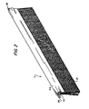
- Figure 2 illustrates the contact charging brush in the form of a planar bristle brush
- the device and method of the present invention may incorporate a brush in a roller configuration as illustrated in Figure 4.
- individual fibers 31 are mounted on or woven or knitted into a conductive resilient base 38 which is then wrapped around a conductive roller 40 connected to an electrical power supply.
- Such a rotary brush maximizes charge uniformity.
- contact brush charging devices are made from fibers having D.C. electrical resisitivity of from about 10 2 ohms-cm to about 10 6 ohms-cm and are substantially resistivity stable in terms of changes in relative humidity and temperature that the pinhole effect and associated copy quality defect described above can be substantially eliminated.
- fiber materials having a resistivity less than 10 2 ohms-cm the amount of power dissipated at the point of the imperfection goes up giving rise to an increase in the pin hole effect and associated copy quality defect.
- resistivities greater than 10 6 ohms-cm and applied voltages of about 1200 volts there will be insufficient current flowing to the photoreceptor to perfect adequate charging of the photoreceptor to be used in the imaging process.
- the preferred balance between electrical resisitivity and conductivity within this range is in the small resistivity range of from about 10 3 ohms-cm to about 10 5 ohms-cm. Fibers having resistivities less than about 10 5 ohms-cm are the most stable in terms of ongoing growth in resistivity. At this point it should be noted that all resistive fibers tend to grow slightly in resistivity with aging.
- Fibers having resistivities greater than 10 3 ohm-cm have better current surge limiting capabilities and therefore are less likely to cause pinholing. While materials exhibiting the general and preferred electrical resistivities have existed in the prior art, it is noted that those materials were generally of the nature described in US-A-2 774 921 and not resistivity stable with respect to changes in relative humidity. In this context what we mean by substantially resistivity stable is less than an order of magnitude change in resistivity based on changes in temperature and relative humidity over normal operating range and ageing. Accordingly we are talking about a stability generally in the range of 60°F to 90°F and 10 to 80% relative humidity.
- Fibers of the present charging brush are resiliently flexible in that if they are deflected by a sheet passing their location they spring back into their original position after the trailing edge of the sheet has passed. Furthermore, if the fibers are compressed for an extended period of time they will return to their original orientation when the compression is removed. They are preferably relatively non-brittle or soft in order to reduce any possible physical deterioration of the photoreceptor. Typically the fibers have an elongation of the tensile stress of from about 1.2% to about 3% of their initial length before they fracture.
- the resistive fibers of the present invention are generally circular in cross section having a diameter of from about 5 microns to about 50 microns and preferably from about 8 microns to about 10 microns which provides them with a reduced tendency to fracture or break.
- any suitable material may be used for the individual fibers in the contact brush charging device of the present invention as long as the fibers exhibit or possess the above described properties.
- the fibers are carbonaceous or have a carbonaceous core.
- a preferred fiber that may be used in a contact charging brush of the present invention are those carbon fibers that are obtained from the low heat treatment temperature processing to yield partial carbonization of the polyacrylonitrile (PAN) precursor fibers. It has been found for such fibers that by carefully controlling the temperature of carbonization within certain limits that precise electrical resistivities for the carbonized carbon fibers may be obtained. In this regard attention is directed to Figure 3 which shows a graph of resistivity and its dependence on process temperature for the carbonization process.
- the polyacrylonitrile precursor fibers are commercially produced by the Stackpole Company, Celanese Corporation and others in yarn bundles of 1,000 filaments to 180,000 filaments.
- the yarn bundles are partially carbonized in a two stage process involving stabilizing the pan fibers at temperatures of the order of 300 0 C in an oxygen atmosphere to produce preox-stabilized PAN followed by carbonization at elevated temperatures in an inert (nitrogen) atmosphere.
- the D.C. electrical resistivity of the resulting fibers is controlled by the selection of the temperature of carbonization. For example, as illustrated in Figure 3 carbon fibers having an electrical resistivity of from about 10 2 to about 10 6 ohms-cm are obtained if the carbonization temperature is controlled in the range of from about 500 o C to 750 0 C.
- Fibers resulting from such a process are stable to changes in temperature and relative humidity in that the electrical resistivity does not change with relative humidity. This is in sharp contrast with materials described in US-A-2 774 921 above referred to above wherein electrical resistivity could change many orders of magnitude with changes in relative humidity.
- the fibers are produced or made without the use of fillers, plasticizers, waxes or other agents that can leach out of the body of the fiber and subsequently lead to contamination of the photoreceptor.
- the fiber produced is substantially homogenous in composition and is relatively pure in the sense that no additives including unbound species are present.
- all the nitrogen and oxygen left in the fiber are bound in some form to the carbon or each other as part of the residual polymer chain.
- the stable nature of the electrical resistivity with regard to temperature and relative humidity is in contrast to most polymeric fibers wherein the conductivity is obtained by adding carbon black and other additives which are physically admixed in one form or another. In the use of such fibers it typically happens that the carbon black or other additives may end up becoming deposited on the photoreceptor.
- the fibers present fibers are capable of being packed very tightly to provide a high fiber fill density (the number of free fiber ends per unit area).
- the contact brush charging devices of the present invention have fiber fill densities of from about 5 x 10 4 to 4 x 10 6 fibers per square inch. These fibers lend themselves to weaving and can therefore be woven into a fabric if desired. In operation, each individual fiber acts as a charging element without mechanically eroding or otherwise defacing the photoreceptor area. Accordingly, the contact charging brush according to the present invention posesses great functional life.
- the preferred carbon fibers used in the practice of the present invention are commercially available from Celanese as CELECT 675. They are made by a variety of processes which are taught generally in the literature. For further reference to the processes that may be employed in making these carbonized fibers attention is directed to the following sources in the literature. "Carbon Fiber Production at Low Temperatures from Polyacryonitrile", D. E. Cagliostro, Textile Research Journal, October 1980, pages 632 - 638; "Description of the Carbonization Process of Polyacrylonitrile Fibers in Terms of Electrical Characteristics:, L. Brehmer et al, Plaste und Kautschuk, 1980, Vol. 27, No. 6, pages 309 - 313. "Electrical Resistance of Carbon Fibers", D. B. Fischbach et al., Department of Mining, Metallurgical and Ceramic Engineering. FB-10, University of Washington, Seattle, Washington, pages 191, 192.
- Figure 3 represents the variation in resistivity with process temperature as the log of resistivity versus process temperature. From this representation it is clear that precision control of the resistivity may be obtained by controlling the temperature of carbonization. Furthermore as pointed out preferred fibers employed in the practice of the present invention are stable in that their resistivity does not change with relative humidity or temperature, they are highly flexible, fine in diameter, exhibit substantially no compression set and an elongation of only 1.2 to 3%.
- the following chart indicates contact brush charging performance for several fibers having different D.C. electrical resistivities.
- a brush having a fiber fill density of about 40,000 fibers per inch and the same geometric dimension was constructed.
- the conductive graphite and stainless steel fibers were made according to the mandrel winding technique of US-A-4,330,349 (Swift et al) wherein a strip of double backed foam adhesive tape was placed on the mandrel, the fibers wound around the mandrel followed by alternate double backed foam adhesive tape and additional fiber windings until a brush having four fiber winding layers was obtained.
- Aluminum strips were then placed on the outside tapes to enclose and laminate the brush and provide electrical contact to the fibers.
- the ends of the brushes were trimmed to a projecting length of about one half inch with a guillotine cutter. Then the back side of the brush was coated with conductive silver paint to assure electrical contact to all fibers and seal the fibers into the brush.
- the Stackpole fibers mentioned in the chart below were supplied as four inch wide tows of 40,000 per inch. These tows were manually layered using strips of double backed foam tape, then aluminum stips were used to enclose the laminate and form the brush root or handle as well as the electrical contact to the fibers. The tows projected perhaps an inch or so from the aluminum and were trimmed to a projecting length of typically one half inch with a guillotine cutter.
- the four inch long brushes with a free fiber length of one half inch were then individually tested by being mounted over a rotating drum bearing a photoconductive surface such as that described in US-A-4,265,990 and in contact with this surface.
- the voltage applied to the brush was ramped from zero to -1500 volts, to deposit a linearly increasing charge density on the photoreceptor which was measured as the drum rotated under an electrometer.
- the slope of the V (photoreceptor) vs. V (applied) line is a measure of charging ability.
- this slope is very nearly unity, i.e., the photoreceptor surface potential tracks the applied voltage independent of other process variations such as speed, hence the term "constant voltage charging".
- the conventional conductive graphite fibers referred to above are available from Hercules, Celanese and Union Carbide were Celion 6000 carbon fibers, Celanese, Chatam, New Jersey; Thornel 50 and 300 (PAN) carbon fibers, Union Carbide, Chicago, Illinois; Magnamite AS4 PAN based graphite fiber Hercules, Wilmington, Delaware.
- the stainless steel fiber is available from Schlegel Corporation, Rochester, New York.
- Panex 30 is available from Stackpole Fibers Company, Lowell, Massachusetts.
- Fibers 1-6 are PAN fibers made by Stackpole and carbonized at the temperature indicated made for Xerox Corporation.
- a contact brush charging device together with a method for charging a photoreceptor has been provided in accordance with the present invention wherein commercially produceable long life materials can be selected which are compatible with the photoreceptor surface and do not produce the "pin hole effect" referred to above.
- the resistivity of the brush charging device can be controlled according to the carbonization temperature.
- the brushes so produced are soft being non-destructive to the photoreceptor in a mechanical sense.
- any shorting out of individual fibers will not adversely effect the charging performance of the brush in that the fibers are self limited in terms of current flow since the current flow in a single fiber during shorting will go to ground on the photoreceptor without decreasing the voltage in the entire brush because of the high resistivity of each individual fiber.
- the preferred fibers according to the present invention do not deposit anything on the photoreceptor in terms of wear, debris, and do not abrade the photoreceptor.
Landscapes
- Physics & Mathematics (AREA)
- Engineering & Computer Science (AREA)
- Plasma & Fusion (AREA)
- General Physics & Mathematics (AREA)
- Electrostatic Charge, Transfer And Separation In Electrography (AREA)
- Brushes (AREA)
Applications Claiming Priority (2)
| Application Number | Priority Date | Filing Date | Title |
|---|---|---|---|
| US66582284A | 1984-10-29 | 1984-10-29 | |
| US665822 | 1984-10-29 |
Publications (3)
| Publication Number | Publication Date |
|---|---|
| EP0180378A2 true EP0180378A2 (de) | 1986-05-07 |
| EP0180378A3 EP0180378A3 (en) | 1986-12-10 |
| EP0180378B1 EP0180378B1 (de) | 1990-06-13 |
Family
ID=24671697
Family Applications (1)
| Application Number | Title | Priority Date | Filing Date |
|---|---|---|---|
| EP19850307466 Expired EP0180378B1 (de) | 1984-10-29 | 1985-10-16 | Kontaktbürstenaufladung |
Country Status (3)
| Country | Link |
|---|---|
| EP (1) | EP0180378B1 (de) |
| JP (1) | JPH0675221B2 (de) |
| DE (1) | DE3578236D1 (de) |
Cited By (4)
| Publication number | Priority date | Publication date | Assignee | Title |
|---|---|---|---|---|
| EP0330820A1 (de) * | 1988-02-25 | 1989-09-06 | Fujitsu Limited | Bürstenartige Kontaktaufladeeinheit für ein Bilderzeugungsgerät |
| EP0294042A3 (de) * | 1987-05-28 | 1989-10-11 | Crosfield Electronics Limited | Tiefdruck |
| EP0400563A3 (de) * | 1989-05-31 | 1991-03-20 | Kabushiki Kaisha Toshiba | Aufzeichnungsgerät |
| EP0549221A1 (de) * | 1991-12-18 | 1993-06-30 | Xerox Corporation | Schalter und Sensoren unter Verwendung von durch Pultrusion hergestellten Kontakten |
Families Citing this family (1)
| Publication number | Priority date | Publication date | Assignee | Title |
|---|---|---|---|---|
| JP6150568B2 (ja) * | 2013-03-12 | 2017-06-21 | キヤノン株式会社 | 画像形成装置 |
Family Cites Families (7)
| Publication number | Priority date | Publication date | Assignee | Title |
|---|---|---|---|---|
| JPS516245B2 (de) * | 1972-08-07 | 1976-02-26 | ||
| JPS49116329A (de) * | 1973-03-13 | 1974-11-07 | ||
| US4336565A (en) * | 1980-08-04 | 1982-06-22 | Xerox Corporation | Charge process with a carbon fiber brush electrode |
| JPS5749965A (en) * | 1980-09-11 | 1982-03-24 | Canon Inc | Friction charger |
| JPS5764754A (en) * | 1980-10-08 | 1982-04-20 | Toshiba Corp | Charging device |
| JPS5767951A (en) * | 1980-10-14 | 1982-04-24 | Toshiba Corp | Electric charger |
| US4555171A (en) * | 1982-03-15 | 1985-11-26 | Schlegel Corporation | Conductive charge/discharge device |
-
1985
- 1985-10-16 DE DE8585307466T patent/DE3578236D1/de not_active Expired - Fee Related
- 1985-10-16 JP JP60230911A patent/JPH0675221B2/ja not_active Expired - Lifetime
- 1985-10-16 EP EP19850307466 patent/EP0180378B1/de not_active Expired
Cited By (7)
| Publication number | Priority date | Publication date | Assignee | Title |
|---|---|---|---|---|
| EP0294042A3 (de) * | 1987-05-28 | 1989-10-11 | Crosfield Electronics Limited | Tiefdruck |
| EP0330820A1 (de) * | 1988-02-25 | 1989-09-06 | Fujitsu Limited | Bürstenartige Kontaktaufladeeinheit für ein Bilderzeugungsgerät |
| US5012282A (en) * | 1988-02-25 | 1991-04-30 | Fujitsu Limited | Brush contact type charging unit in an image forming apparatus |
| EP0400563A3 (de) * | 1989-05-31 | 1991-03-20 | Kabushiki Kaisha Toshiba | Aufzeichnungsgerät |
| US5148219A (en) * | 1989-05-31 | 1992-09-15 | Kabushiki Kaisha Toshiba | Image forming apparatus with developing and cleaning system |
| EP0549221A1 (de) * | 1991-12-18 | 1993-06-30 | Xerox Corporation | Schalter und Sensoren unter Verwendung von durch Pultrusion hergestellten Kontakten |
| US5420465A (en) * | 1991-12-18 | 1995-05-30 | Xerox Corporation | Switches and sensors utilizing pultrusion contacts |
Also Published As
| Publication number | Publication date |
|---|---|
| DE3578236D1 (de) | 1990-07-19 |
| EP0180378A3 (en) | 1986-12-10 |
| EP0180378B1 (de) | 1990-06-13 |
| JPS61109067A (ja) | 1986-05-27 |
| JPH0675221B2 (ja) | 1994-09-21 |
Similar Documents
| Publication | Publication Date | Title |
|---|---|---|
| US4761709A (en) | Contact brush charging | |
| EP0400563B1 (de) | Aufzeichnungsgerät | |
| US4835807A (en) | Cleaning brush | |
| US4553191A (en) | Static eliminator | |
| US5354607A (en) | Fibrillated pultruded electronic components and static eliminator devices | |
| EP0370818B1 (de) | Elektrische Verbindung mit zwei Elementen | |
| EP0045595A1 (de) | Elektrostatographisches Verfahren und Vorrichtung | |
| US4555171A (en) | Conductive charge/discharge device | |
| US4506975A (en) | Cleaning device | |
| US4963738A (en) | Flat comb-like scorotron charging device | |
| US5220481A (en) | Composite to enable contact electrostatic voltage sensing | |
| EP0180378B1 (de) | Kontaktbürstenaufladung | |
| GB2065032A (en) | Image recording method and apparatus | |
| EP0507055A2 (de) | Bilderzeugungsgerät | |
| EP0523631A2 (de) | Elektrophotographisches Druckgerät | |
| CA1160444A (en) | Development system | |
| JPS61232480A (ja) | 残留トナー除去方法及び装置 | |
| JPS5934573A (ja) | 画像形成装置 | |
| US5937254A (en) | Method and apparatus for cleaning remnant toner and carrier particles | |
| JP3045746B2 (ja) | 電子写真方法 | |
| US5781833A (en) | Sealed liquid charging apparatus | |
| US5105223A (en) | Screened blade scorotron | |
| JP3304482B2 (ja) | 接触帯電装置及び画像形成装置 | |
| JPH0324669B2 (de) | ||
| US5860046A (en) | Charging method and charging device |
Legal Events
| Date | Code | Title | Description |
|---|---|---|---|
| PUAI | Public reference made under article 153(3) epc to a published international application that has entered the european phase |
Free format text: ORIGINAL CODE: 0009012 |
|
| AK | Designated contracting states |
Kind code of ref document: A2 Designated state(s): DE FR GB |
|
| PUAL | Search report despatched |
Free format text: ORIGINAL CODE: 0009013 |
|
| AK | Designated contracting states |
Kind code of ref document: A3 Designated state(s): DE FR GB |
|
| 17P | Request for examination filed |
Effective date: 19870609 |
|
| 17Q | First examination report despatched |
Effective date: 19890123 |
|
| GRAA | (expected) grant |
Free format text: ORIGINAL CODE: 0009210 |
|
| AK | Designated contracting states |
Kind code of ref document: B1 Designated state(s): DE FR GB |
|
| REF | Corresponds to: |
Ref document number: 3578236 Country of ref document: DE Date of ref document: 19900719 |
|
| ET | Fr: translation filed | ||
| PLBE | No opposition filed within time limit |
Free format text: ORIGINAL CODE: 0009261 |
|
| STAA | Information on the status of an ep patent application or granted ep patent |
Free format text: STATUS: NO OPPOSITION FILED WITHIN TIME LIMIT |
|
| 26N | No opposition filed | ||
| PGFP | Annual fee paid to national office [announced via postgrant information from national office to epo] |
Ref country code: FR Payment date: 20011010 Year of fee payment: 17 |
|
| PGFP | Annual fee paid to national office [announced via postgrant information from national office to epo] |
Ref country code: GB Payment date: 20011017 Year of fee payment: 17 |
|
| PGFP | Annual fee paid to national office [announced via postgrant information from national office to epo] |
Ref country code: DE Payment date: 20011029 Year of fee payment: 17 |
|
| REG | Reference to a national code |
Ref country code: GB Ref legal event code: IF02 |
|
| PG25 | Lapsed in a contracting state [announced via postgrant information from national office to epo] |
Ref country code: GB Free format text: LAPSE BECAUSE OF NON-PAYMENT OF DUE FEES Effective date: 20021016 |
|
| PG25 | Lapsed in a contracting state [announced via postgrant information from national office to epo] |
Ref country code: DE Free format text: LAPSE BECAUSE OF NON-PAYMENT OF DUE FEES Effective date: 20030501 |
|
| GBPC | Gb: european patent ceased through non-payment of renewal fee |
Effective date: 20021016 |
|
| PG25 | Lapsed in a contracting state [announced via postgrant information from national office to epo] |
Ref country code: FR Free format text: LAPSE BECAUSE OF NON-PAYMENT OF DUE FEES Effective date: 20030630 |
|
| REG | Reference to a national code |
Ref country code: FR Ref legal event code: ST |