EP0179653B1 - Dünnfilmmagnetkopf - Google Patents
Dünnfilmmagnetkopf Download PDFInfo
- Publication number
- EP0179653B1 EP0179653B1 EP85307629A EP85307629A EP0179653B1 EP 0179653 B1 EP0179653 B1 EP 0179653B1 EP 85307629 A EP85307629 A EP 85307629A EP 85307629 A EP85307629 A EP 85307629A EP 0179653 B1 EP0179653 B1 EP 0179653B1
- Authority
- EP
- European Patent Office
- Prior art keywords
- casing
- head
- assembly according
- thin
- magnetic head
- Prior art date
- Legal status (The legal status is an assumption and is not a legal conclusion. Google has not performed a legal analysis and makes no representation as to the accuracy of the status listed.)
- Expired
Links
- 239000010409 thin film Substances 0.000 title claims description 16
- 239000002184 metal Substances 0.000 claims description 19
- 239000000758 substrate Substances 0.000 claims description 13
- 229920001971 elastomer Polymers 0.000 claims description 6
- 239000000806 elastomer Substances 0.000 claims description 6
- 239000003990 capacitor Substances 0.000 description 9
- 238000000034 method Methods 0.000 description 8
- 239000011347 resin Substances 0.000 description 4
- 229920005989 resin Polymers 0.000 description 4
- 238000010586 diagram Methods 0.000 description 3
- 239000000956 alloy Substances 0.000 description 2
- 239000000919 ceramic Substances 0.000 description 2
- 239000011521 glass Substances 0.000 description 2
- 239000000463 material Substances 0.000 description 2
- 229910000859 α-Fe Inorganic materials 0.000 description 2
- 229910003271 Ni-Fe Inorganic materials 0.000 description 1
- 229910045601 alloy Inorganic materials 0.000 description 1
- 230000015556 catabolic process Effects 0.000 description 1
- 238000006731 degradation reaction Methods 0.000 description 1
- 238000001514 detection method Methods 0.000 description 1
- 238000005530 etching Methods 0.000 description 1
- 239000010408 film Substances 0.000 description 1
- 238000009434 installation Methods 0.000 description 1
- 230000010354 integration Effects 0.000 description 1
- 230000005389 magnetism Effects 0.000 description 1
- 230000000873 masking effect Effects 0.000 description 1
- 230000002093 peripheral effect Effects 0.000 description 1
- 229910000889 permalloy Inorganic materials 0.000 description 1
- 230000035699 permeability Effects 0.000 description 1
- 239000004065 semiconductor Substances 0.000 description 1
- 230000005236 sound signal Effects 0.000 description 1
Images



Classifications
-
- G—PHYSICS
- G11—INFORMATION STORAGE
- G11B—INFORMATION STORAGE BASED ON RELATIVE MOVEMENT BETWEEN RECORD CARRIER AND TRANSDUCER
- G11B20/00—Signal processing not specific to the method of recording or reproducing; Circuits therefor
- G11B20/10—Digital recording or reproducing
- G11B20/10527—Audio or video recording; Data buffering arrangements
-
- G—PHYSICS
- G11—INFORMATION STORAGE
- G11B—INFORMATION STORAGE BASED ON RELATIVE MOVEMENT BETWEEN RECORD CARRIER AND TRANSDUCER
- G11B5/00—Recording by magnetisation or demagnetisation of a record carrier; Reproducing by magnetic means; Record carriers therefor
- G11B5/127—Structure or manufacture of heads, e.g. inductive
- G11B5/31—Structure or manufacture of heads, e.g. inductive using thin films
- G11B5/3103—Structure or manufacture of integrated heads or heads mechanically assembled and electrically connected to a support or housing
Definitions
- the present invention relates to an improved thin-film magnetic head device, and more specifically to a thin-film magnetic head of the type which reproduces digitally recorded signals from magnetic tape.
- Fig. 1 shows a typical example of a conventional device used to reproduce PCM signals recorded on multiple tracks.
- the PCM signals recorded on magnetic tape 1 are reproduced by the playback head 2, and are then amplified to the needed level by amplifier circuit 3.
- the amplified PCM signals are then subjected to waveform equalization by the waveform equalizer circuit 4 after which they are sent to level detection circuit 5 and then converted into digital pulse signals by decoding circuit 6.
- This digital information is then input to the digital signal processing circuit 7, where it is demodulated and subjected to phase correction.
- These demodulated signals are then converted to analogue signals by D/A converter 8 and output at audio signal output terminal 9.
- constant-current source 10 delivers constant current to the yoke-type magnetic resistor (YMR) 11 (in this case the reproducing thin-film magnetic head itself), and as a result, a specific voltage signal is generated by the varied magnetic resistance.
- YMR yoke-type magnetic resistor
- a high-pass filter composed of capacitor 12 and resistor 13 filters out the DC components, and the resultant AC signal is then amplified by amplifier circuit 3.
- These AC signals, reproduced and amplified by multiple tracks, are then selected in sequence by analogue multiplexer 14, and converted again into digital signals by A/D converter 15. These digitalized signals are then processed by digital waveform equalizer circuit 16 to eventually generate signal 17.
- the conventional configuration must still include those circuits arranged between the yoke-type magnetic resistor (yoke-type magnetic head) 11 and the signal switching circuit 14; in other words, circuits corresponding in number to the number of tracks.
- those circuits beyond the constant-current source 10 and capacitor 12 are located outside the casing of the magnetic head 11 (YMR), and these circuits are connected to each other by means of wires or a flexible printed circuit board (hereinafter called FPC).
- FPC flexible printed circuit board
- Fig. 3 is a sectional view of a conventional magnetic head assembly.
- a yoke-type magnetic resistance is generated inside ferrite substrate 21 and protection glass 20.
- the magnetic heads are mounted inside metal casings 18 and 19. Connection between the magnetic heads and the external reproducing circuits is achieved by bonding the flexible printed circuit board 23 with metal casing 19.
- the magnetic head and flexible printed circuit board 23 are connected by wire bond or other form of wire 22.
- the magnetic heads are connected in turn to external circuits by means of the flexible printed circuit board.
- Space inside metal casings 18 and 19 is filled with molded resin 32.
- the conventional head-installation method described above could potentially generate many errors due to low output signals and a poor S/N ratio for all data. This unwanted phenomenon as mentioned earlier, increases in proportion to the number of tracks in the tape, thus resulting in critical problems in actual use.
- FR-A-2443733 describes an integrated, multi-track, magnetic reading head which is produced by semiconductor integration processes. It comprises a system of magneto-electric transducers, each fulfilling the function of an elementary head and associated circuitry.
- DE-A-3150322 relates to a multiple magnetic head device suitable for recording video signals.
- the head unit is formed by masking and etching techniques resulting in a series of equally spaced ridges, each of which is provided with an electrical terminal.
- the invention aims to overcome, at least in part, see of the disadvantages outlined above in relation to the prior art.
- a multi-track head assembly comprising; a shield casing; and a thin film magnetic head having a plurality of head elements mounted in the casing; characterised by a plurality of circuits disposed in the casing, one for each head element, wherein each circuit comprises a capacitance mounted on a first substrate and a resistance mounted on a second substrate, each said capacitance and its respective resistance being interconnected by an electrically conductive elastomer.
- a thin-film magnetic-head assembly for a digital recording/reproducing device using multiple tracks.
- the preferred device is comprised of the following: various electronic-circuit components including a combined capacitor/resistor, a constant-current source, a reproduced-signal amplifier, and an analogue multiplex. All are located inside a casing surrounding the thin-film magnetic head(s), and respective components of each circuit on the upper and lower surfaces of said casing are connected to each other by means of an elastomer. These circuits are thereby integrally connected to said thin-film magnetic head(s).
- the multi-track head assembly is installed in a position opposite magnetic tape 1.
- Upper and lower surfaces 18 and 19 of the metal casing and the yoke-type magnetic resistance element (YMR) protection glass 20 are mounted on the ferrite substrate 21.
- the thin-film magnetic-head assembly is also provided with: fine wire (e.g. wire bond) 22, substrates made of either ceramic or other hard material 24 and 26, capacitor 25, resistor 27, elastomer 28, flexible printed circuit board (FPC) 29, amplifier combined with an analogue-signal multiplexer IC circuit 30, constant current source, and the molded resin 32 which fills all remaining space in the metal.
- Upper and lower surfaces 18 and 19 of the metal casing are provided with either ceramic or hard material substrates 24 and 26, respectively.
- a number of monolithic capacitors (or thin-film capacitors) 25 are installed on the upper substrate 24, whereas a number of chip resistors (or thick-film resistors) 27 are installed on the lower substrate 26.
- Each capacitor 25 on substrate 24 and its respective resistance 27 on substrate 26 are electrically connected to each other via an elastomer 28.
- One end of the flexible printed circuit board 29 is connected to substrate 26, while the other end provides external connection through metal casing 19.
- the circuit 30 comprising an amplifier and an analogue multiplexer IC is installed on flexible printed circuit board 29 inside the metal casing 19.
- the constant current source 31 is also installed on the flexible printed circuit board 29, and the inner space of said metal casing 19 is entirely filled with molded resin 32 to simplify the wiring.
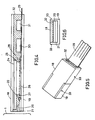
- Fig. 5 is the external view of the thin-film magnetic-head assembly shown in Fig. 4.
- the flexible printed circuit board 29 is connected to the A/D converter of the external circuit and to the power source.
- Fig. 7 is an enlarged view of a thin-film magnetic-head assembly of a preferred embodiment of the present invention. It shows an FPC of similar configuration to that shown in Fig. 4 but with the bottom surface 34 of the metal casing bent in an "L" shape. Flexible printed circuit board 29 exits the metal casing at the bottom on the metal casing. The IC circuit 30 covered by molded resin 32 and the constant current source 31 are located on FPC 29. Considering the movement of the thin-film magnetic head in the direction of the magnetic tape 1, the bent-and-extended bottom surface of the metal casing 34 has an advantageous depth, being shorter than that of the metal casing shown in Fig. 4. This provides a significant advantage in actual use. In addition, since the FPC 29 is in a position perpendicular to the magnetic head, it can be connected to external circuits very easily.
- this digital-signal recording and reproducing device dealing with multi-track signals does not require a number of circuit-wires for distribution purposes. As a result, the signal quality can be satisfactorily maintained without any degradation, drastically minimizing data signal errors.
Landscapes
- Engineering & Computer Science (AREA)
- Multimedia (AREA)
- Signal Processing (AREA)
- Manufacturing & Machinery (AREA)
- Magnetic Heads (AREA)
- Recording Or Reproducing By Magnetic Means (AREA)
Claims (10)
- Mehrspur-Kopfanordnung mit:einem Abschirmungsgehäuse (18, 19;) undeinem Dünnschicht-Magnetkopf, der eine Anzahl von Kopfelementen (20, 21) aufweist, die in dem Gehäuse angeordnet sind;gekennzeichnet durch eine Anzahl von Schaltkreisen, die in dem Gehäuse angeordnet sind, und zwar einer für jedes Kopfelement, wobei jeder Schaltkreis einen Kondensator (25) besitzt, der auf einem ersten Substrat (24) gebildet ist, und einen Widerstand (27), der auf einem zweiten Substrat (26) sitzt, wobei jeder Kondensator und jeder zugehörige Widerstand durch ein elektrisch-leitendes Elastomeres (28) miteinander verbunden sind.
- Anordnung nach Anspruch 1, wobei eine Anzahl von Verstärkern (30) in dem Gehäuse angeordnet ist, und zwar einer für jedes Kopfelement.
- Anordnung nach Anspruch 1 oder 2, wobei eine Anzahl von Konstantstromreglern in dem Gehäuse angeordnet ist, und zwar einer für jedes Kopfelement.
- Anordnung nach einem der vorhergehenden Ansprüche, wobei ein Multiplexer in dem Gehäuse angeordnet ist, der für alle Kopfelemente da ist.
- Anordnung nach Anspruch 1, wobei das Gehäuse einen verlängerten Wandabschnitt (34) aufweist, auf dem eine Anzahl von Verstärkern (30) sitzt, und zwar einer für jedes Kopfelement.
- Anordnung nach Anspruch 5, wobei ein Multiplexer auf dem verlängerten Wandabschnitt angeordnet ist, der für alle Kopfelemente da ist.
- Anordnung nach einem der vorhergehenden Ansprüche, wobei die Widerstände und/oder die Kondensatoren und/oder die Verstärker und/oder der Multiplexer integriert sind.
- Anordnung nach einem der Ansprüche 5 bis 7, wobei der verlängerte Wandabschnitt gekrümmt ist.
- Anordnung nach einem der vorhergehenden Ansprüche, wobei das Abschirmgehäuse ein Metallgehäuse ist.
- Anordnung nach einem der vorhergehenden Ansprüche, wobei der Dünnschicht-Magnetkopf ein jochartiges Magnetwiderstandselement aufweist.
Applications Claiming Priority (2)
| Application Number | Priority Date | Filing Date | Title |
|---|---|---|---|
| JP223577/84 | 1984-10-22 | ||
| JP59223577A JPS61104313A (ja) | 1984-10-22 | 1984-10-22 | 薄膜磁気ヘツド装置 |
Publications (2)
| Publication Number | Publication Date |
|---|---|
| EP0179653A1 EP0179653A1 (de) | 1986-04-30 |
| EP0179653B1 true EP0179653B1 (de) | 1991-05-15 |
Family
ID=16800341
Family Applications (1)
| Application Number | Title | Priority Date | Filing Date |
|---|---|---|---|
| EP85307629A Expired EP0179653B1 (de) | 1984-10-22 | 1985-10-22 | Dünnfilmmagnetkopf |
Country Status (5)
| Country | Link |
|---|---|
| US (1) | US4739431A (de) |
| EP (1) | EP0179653B1 (de) |
| JP (1) | JPS61104313A (de) |
| CA (1) | CA1240039A (de) |
| DE (1) | DE3582853D1 (de) |
Families Citing this family (17)
| Publication number | Priority date | Publication date | Assignee | Title |
|---|---|---|---|---|
| JPH0782630B2 (ja) * | 1989-02-28 | 1995-09-06 | 三菱電機株式会社 | 薄膜磁気ヘッド装置 |
| US20020176210A1 (en) * | 1989-11-27 | 2002-11-28 | Hamilton Harold J. | Durable, low-vibration, dynamic-contact hard disk drive system |
| US5483025A (en) * | 1989-11-27 | 1996-01-09 | Censtor Corporation | Unitary micro-flexure structure |
| US5453315A (en) * | 1989-11-27 | 1995-09-26 | Censtor Corp. | Unitary micro-flexure structure and method of making same |
| US5111351A (en) * | 1989-11-27 | 1992-05-05 | Censtor Corp. | Integrated magnetic read/write head/flexure/conductor structure |
| US5476131A (en) * | 1989-11-27 | 1995-12-19 | Censtor Corporation | Unitary micro-flexure structure and method of making same |
| US6600631B1 (en) | 1989-11-27 | 2003-07-29 | Censtor Corp. | Transducer/flexure/conductor structure for electromagnetic read/write system |
| US5041932A (en) * | 1989-11-27 | 1991-08-20 | Censtor Corp. | Integrated magnetic read/write head/flexure/conductor structure |
| EP0576680B1 (de) * | 1992-01-20 | 2004-03-31 | Fujitsu Limited | Magnetkopfanordnung, dessen herstellung und magnetplattengerät |
| EP0580442A2 (de) * | 1992-07-23 | 1994-01-26 | Censtor Corporation | Integrierte Struktur mit Lese-/Schreibemagnetkopf, Biegung und Leiter |
| JPH06168556A (ja) * | 1992-08-25 | 1994-06-14 | Internatl Business Mach Corp <Ibm> | 変換器及び懸架部の組合せアセンブリ、及びその処理方法並びに該アセンブリを有するデータ処理装置 |
| US6341415B2 (en) | 1992-08-31 | 2002-01-29 | Fujitsu Limited | Method for assembling a magnetic head assembly and magnetic disk drive using bonding balls connecting magnetic head terminals to wiring terminals |
| US5606598A (en) * | 1992-11-24 | 1997-02-25 | Casio Phonemate, Inc. | Telephone answering device with direct telephone line interface |
| US5862014A (en) * | 1996-01-11 | 1999-01-19 | Quantum Corporation | Multi-channel magnetic tape head module including flex circuit |
| US6885522B1 (en) | 1999-05-28 | 2005-04-26 | Fujitsu Limited | Head assembly having integrated circuit chip covered by layer which prevents foreign particle generation |
| US6535342B1 (en) * | 1999-12-09 | 2003-03-18 | International Business Machines Corporation | Apparatus, system and method for writing information onto magnetic media field of the invention |
| JP2002100016A (ja) * | 2000-09-21 | 2002-04-05 | Toshiba Corp | ヘッドサスペンションアッセンブリ |
Family Cites Families (9)
| Publication number | Priority date | Publication date | Assignee | Title |
|---|---|---|---|---|
| JPS573132B2 (de) * | 1974-01-19 | 1982-01-20 | ||
| US4191983A (en) * | 1977-06-24 | 1980-03-04 | Applied Magnetics Corporation | Thin film magnetic head assembly having a thin film magnetic transducer encapsulated in insulating bonding material |
| DE2819208C2 (de) * | 1978-05-02 | 1984-10-31 | Siemens AG, 1000 Berlin und 8000 München | Mehrfach-Dünnschicht-Magnetkopf zur Bandaufzeichnung von Hochfrequenzsignalen |
| FR2443733A1 (fr) * | 1978-12-08 | 1980-07-04 | Thomson Csf | Tete de lecture magnetique et lecteur muni d'une telle tete |
| NL7901577A (nl) * | 1979-02-28 | 1980-09-01 | Philips Nv | Meerspoors dunne film magneetkop. |
| US4281357A (en) * | 1979-09-10 | 1981-07-28 | Magnex Corporation | Thin film magnetic head and method of making the same |
| DE3150322A1 (de) * | 1981-12-18 | 1983-06-30 | Agfa-Gevaert Ag, 5090 Leverkusen | Verfahren zur herstellung einer mehrfachduennfilmkopfeinheit |
| US4520413A (en) * | 1982-04-13 | 1985-05-28 | Minnesota Mining And Manufacturing Company | Integrated magnetostrictive-piezoelectric-metal oxide semiconductor magnetic playback head |
| JPS5971414U (ja) * | 1982-10-29 | 1984-05-15 | ソニー株式会社 | マルチトラツク再生ヘツド装置 |
-
1984
- 1984-10-22 JP JP59223577A patent/JPS61104313A/ja active Granted
-
1985
- 1985-10-17 CA CA000493221A patent/CA1240039A/en not_active Expired
- 1985-10-22 US US06/790,221 patent/US4739431A/en not_active Expired - Lifetime
- 1985-10-22 EP EP85307629A patent/EP0179653B1/de not_active Expired
- 1985-10-22 DE DE8585307629T patent/DE3582853D1/de not_active Expired - Lifetime
Also Published As
| Publication number | Publication date |
|---|---|
| DE3582853D1 (en) | 1991-06-20 |
| JPH0330205B2 (de) | 1991-04-26 |
| JPS61104313A (ja) | 1986-05-22 |
| US4739431A (en) | 1988-04-19 |
| EP0179653A1 (de) | 1986-04-30 |
| CA1240039A (en) | 1988-08-02 |
Similar Documents
| Publication | Publication Date | Title |
|---|---|---|
| EP0179653B1 (de) | Dünnfilmmagnetkopf | |
| US6542321B1 (en) | Bidirectional read-while-write data recording system | |
| NZ212062A (en) | Reproduction of analogue and digital signals carried on magnetic disc | |
| EP0744750A2 (de) | Kapazitive Schnittstelle zwischen einem Musikchip und einem Audiospieler | |
| US5633765A (en) | Adaptive pole-zero cancellation for wide bandwidth magnetoresistive pre-amplifier | |
| JPS58118017A (ja) | 磁気ヘツド | |
| JP2707191B2 (ja) | マルチトラック磁気信号再生装置 | |
| US6046876A (en) | Head signal device with noise immunity function, for use in a disk storage apparatus | |
| JPS61148607A (ja) | マルチトラツク磁気信号再生装置 | |
| JPS6258042B2 (de) | ||
| US4568987A (en) | Amplifier input circuit having a figure eight conductive pattern | |
| JPS60109106A (ja) | 磁気ヘッド用フレキシブルケ−ブル | |
| EP0581349A3 (en) | System for recording and/or reproducing information signals, as well as cassette and apparatus for the system | |
| JPH0438705A (ja) | マルチトラック再生回路 | |
| JPH0474766B2 (de) | ||
| ATE20985T1 (de) | Geraet zur wiedergabe von einem aufzeichnungstraeger. | |
| SU896687A1 (ru) | Устройство дл записи и воспроизведени на магнитных дисках | |
| JPS6161220A (ja) | 磁気記録再生システム | |
| JPS59127209A (ja) | 磁気媒体読出し時の外来ノイズ除去方法 | |
| JPH06124420A (ja) | 磁気抵抗効果型ヘッド及び磁気抵抗効果型ヘッド用信号再生装置 | |
| JPH03232103A (ja) | 磁気記録装置のクロストーク除去方法 | |
| EP0421692A2 (de) | Magnetisches Datenspeichergerät | |
| JPH06333203A (ja) | 磁気ヘッド装置 | |
| KR940006075A (ko) | 기록 및 재생 장치 | |
| JPS59191941A (ja) | 自動等化回路 |
Legal Events
| Date | Code | Title | Description |
|---|---|---|---|
| PUAI | Public reference made under article 153(3) epc to a published international application that has entered the european phase |
Free format text: ORIGINAL CODE: 0009012 |
|
| AK | Designated contracting states |
Kind code of ref document: A1 Designated state(s): DE FR GB IT NL |
|
| 17P | Request for examination filed |
Effective date: 19860929 |
|
| 17Q | First examination report despatched |
Effective date: 19880225 |
|
| GRAA | (expected) grant |
Free format text: ORIGINAL CODE: 0009210 |
|
| AK | Designated contracting states |
Kind code of ref document: B1 Designated state(s): DE FR GB IT NL |
|
| ITF | It: translation for a ep patent filed | ||
| REF | Corresponds to: |
Ref document number: 3582853 Country of ref document: DE Date of ref document: 19910620 |
|
| ET | Fr: translation filed | ||
| PLBE | No opposition filed within time limit |
Free format text: ORIGINAL CODE: 0009261 |
|
| STAA | Information on the status of an ep patent application or granted ep patent |
Free format text: STATUS: NO OPPOSITION FILED WITHIN TIME LIMIT |
|
| 26N | No opposition filed | ||
| PGFP | Annual fee paid to national office [announced via postgrant information from national office to epo] |
Ref country code: NL Payment date: 19981028 Year of fee payment: 14 |
|
| PG25 | Lapsed in a contracting state [announced via postgrant information from national office to epo] |
Ref country code: NL Free format text: LAPSE BECAUSE OF NON-PAYMENT OF DUE FEES Effective date: 20000501 |
|
| NLV4 | Nl: lapsed or anulled due to non-payment of the annual fee |
Effective date: 20000501 |
|
| REG | Reference to a national code |
Ref country code: GB Ref legal event code: IF02 |
|
| PGFP | Annual fee paid to national office [announced via postgrant information from national office to epo] |
Ref country code: FR Payment date: 20041008 Year of fee payment: 20 |
|
| PGFP | Annual fee paid to national office [announced via postgrant information from national office to epo] |
Ref country code: DE Payment date: 20041014 Year of fee payment: 20 |
|
| PGFP | Annual fee paid to national office [announced via postgrant information from national office to epo] |
Ref country code: GB Payment date: 20041020 Year of fee payment: 20 |
|
| PG25 | Lapsed in a contracting state [announced via postgrant information from national office to epo] |
Ref country code: GB Free format text: LAPSE BECAUSE OF EXPIRATION OF PROTECTION Effective date: 20051021 |
|
| REG | Reference to a national code |
Ref country code: GB Ref legal event code: PE20 |