EP0179367A2 - Eyelet assembly - Google Patents
Eyelet assembly Download PDFInfo
- Publication number
- EP0179367A2 EP0179367A2 EP85112919A EP85112919A EP0179367A2 EP 0179367 A2 EP0179367 A2 EP 0179367A2 EP 85112919 A EP85112919 A EP 85112919A EP 85112919 A EP85112919 A EP 85112919A EP 0179367 A2 EP0179367 A2 EP 0179367A2
- Authority
- EP
- European Patent Office
- Prior art keywords
- eyelet
- projections
- cylindrical portion
- seat plate
- assembly
- Prior art date
- Legal status (The legal status is an assumption and is not a legal conclusion. Google has not performed a legal analysis and makes no representation as to the accuracy of the status listed.)
- Ceased
Links
- 230000002093 peripheral effect Effects 0.000 claims abstract description 14
- 239000004033 plastic Substances 0.000 claims abstract description 12
- 239000004744 fabric Substances 0.000 description 23
- 239000000463 material Substances 0.000 description 2
- 229920002292 Nylon 6 Polymers 0.000 description 1
- 230000000712 assembly Effects 0.000 description 1
- 238000000429 assembly Methods 0.000 description 1
- -1 polybutylene Polymers 0.000 description 1
- 229920001748 polybutylene Polymers 0.000 description 1
Images


Classifications
-
- A—HUMAN NECESSITIES
- A44—HABERDASHERY; JEWELLERY
- A44B—BUTTONS, PINS, BUCKLES, SLIDE FASTENERS, OR THE LIKE
- A44B1/00—Buttons
- A44B1/18—Buttons adapted for special ways of fastening
- A44B1/28—Buttons adapted for special ways of fastening with shank and counterpiece
- A44B1/34—Buttons adapted for special ways of fastening with shank and counterpiece with snap-action counterpiece
-
- A—HUMAN NECESSITIES
- A44—HABERDASHERY; JEWELLERY
- A44B—BUTTONS, PINS, BUCKLES, SLIDE FASTENERS, OR THE LIKE
- A44B13/00—Hook or eye fasteners
- A44B13/0058—Eyelets or grommets
- A44B13/0064—Eyelets or grommets characterised by their material
- A44B13/007—Eyelets or grommets characterised by their material made of plastics
-
- A—HUMAN NECESSITIES
- A44—HABERDASHERY; JEWELLERY
- A44B—BUTTONS, PINS, BUCKLES, SLIDE FASTENERS, OR THE LIKE
- A44B13/00—Hook or eye fasteners
- A44B13/0058—Eyelets or grommets
- A44B13/0076—Eyelets or grommets characterised by their way of fastening to the support
- A44B13/0088—Eyelets or grommets characterised by their way of fastening to the support by separable snap connection
-
- F—MECHANICAL ENGINEERING; LIGHTING; HEATING; WEAPONS; BLASTING
- F16—ENGINEERING ELEMENTS AND UNITS; GENERAL MEASURES FOR PRODUCING AND MAINTAINING EFFECTIVE FUNCTIONING OF MACHINES OR INSTALLATIONS; THERMAL INSULATION IN GENERAL
- F16B—DEVICES FOR FASTENING OR SECURING CONSTRUCTIONAL ELEMENTS OR MACHINE PARTS TOGETHER, e.g. NAILS, BOLTS, CIRCLIPS, CLAMPS, CLIPS OR WEDGES; JOINTS OR JOINTING
- F16B21/00—Means for preventing relative axial movement of a pin, spigot, shaft or the like and a member surrounding it; Stud-and-socket releasable fastenings
- F16B21/10—Means for preventing relative axial movement of a pin, spigot, shaft or the like and a member surrounding it; Stud-and-socket releasable fastenings by separate parts
- F16B21/16—Means for preventing relative axial movement of a pin, spigot, shaft or the like and a member surrounding it; Stud-and-socket releasable fastenings by separate parts with grooves or notches in the pin or shaft
- F16B21/18—Means for preventing relative axial movement of a pin, spigot, shaft or the like and a member surrounding it; Stud-and-socket releasable fastenings by separate parts with grooves or notches in the pin or shaft with circlips or like resilient retaining devices, i.e. resilient in the plane of the ring or the like; Details
- F16B21/186—Means for preventing relative axial movement of a pin, spigot, shaft or the like and a member surrounding it; Stud-and-socket releasable fastenings by separate parts with grooves or notches in the pin or shaft with circlips or like resilient retaining devices, i.e. resilient in the plane of the ring or the like; Details external, i.e. with contracting action
Definitions
- This invention relates to an eyelet assembly including an eyelet body and a seat plate formed by plastic material which are adapted to be assembled together on a piece of fabric or the like.
- the eyelet assembly of this prior art includes the plastic seat plate A and plastic eyelet body B which is adapted to be fit in the seat plate A.
- the external peripheral surface of the cylindrical portion of the eyelet body B is provided with a plurality of annular horizontal projections C having a saw-tooth cross section in vertically spaced relationship.
- projections are adapted to engage the engaging portion D formed at the inner edge of the annular seat plate A with fabric pinched between the flange of the eyelet body B and the seat plate A.
- the position at which the projections C engage with the engaging portion D may be changed depending on variations in the thickness of the fabric.
- a primary object of the present invention is to provide an eyelet assembly which is applicable to a thin fabric by improving the shape and position of the projections on the external peripheral surface of the cylindrical portion of the eyelet body.
- the present invention is constructed as an eyelet assembly wherein a plurality of arcuate projections of a predetermined thickness are formed on the external peripheral surface of the cylindrical portion of the eyelet body vertically spaced from each other, each arcuate projection extending by an angular distance which is less than a quarter of the circumference of the cylindrical portion and the projections in vertically adjacent levels are staggered horizontally so that they do not overlap each other vertically when viewed from the front side of the eyelet body.
- the projections in the veritcally adjacent levels on the eyelet body are staggered horizontally so that they do not overlap vertically, the projections on the eyelet body as well as the engaging portions of the seat plate can be formed relatively thick and thus, even if the pitch of the projections on the eyelet body is made fine, the strength of the projections and the engaging portions will not be reduced.
- the eyelet body can be provided with fine pitched projections in such a way that the engaging position between the projection of the eyelet body and the engaging portion of the seat plate can be changed depending upon the thickness of the fabric to which the eyelet assembly is attached.
- the eyelet body 1 is formed of soft plastic such as Nylon 6 and comprises a hollow cylindrical portion 2 and a flange 3 extending radially outwardly from the upper end of the cylindrical portion.
- the undersurface of the flange 3 is formed with four detents 5 in an equally spaced relationship in the circumferential direction of the flange so that when the eyelet body 1 is assembled with a seat plate 6 (which will be described hereinbelow), the detents 5 bite into the fabric to thereby prevent the eyelet body from rotating relative to the fabric.
- a seat plate 6 which will be described hereinbelow
- a first pair of outwardly extending and diametrically opposing projections 4a, 4a are formed on the external peripheral surface of the cylindrical portion 2 each covering the angular distance of a quarter of the circumference of the cylindrical portion and similarly, a second pair of outwardly extending and diametrically opposing projections 4b, 4b are formed on the external peripheral surface of the cylindrical portion 2 each covering the angular distance of a quarter of the circumference of the cylindrical portion.
- first and second pairs of projections 4a, 4a and 4b, 4b are positioned at vertically different levels and are horizontally staggered so that they do not overlap each other veritcally when viewed from the front side of the eyelet boby 1.
- the arrangement of these projections 4a, 4a, 4b, 4b is one of the features of the present invention.
- the first and second pairs of projections 4a, 4a and 4b, 4b have a uniform thickness and a trapezoidal sectional configuration including a flat top surface and a sloped lower surface.
- the seat plate 6 is formed of hard plastic such as polybutylene terephtalate (PBT) and as more clearly shown in Figs. 4 and 5, the seat plate 6 is formed with a center hole 11 in which the cylindrical portion 2 of the eyelet body 1 is fitted. As more clearly shown in Fig. 5, the inner peripheral edge of the hole 11 is formed with four equally spaced engaging portions 8 separated by recesses therebetween and having a uniform thickness and the outer peripheral portion 7 of the seat plate 6 is formed with four arcuate grooves 9 corresponding to the engaging portions 8 in position (Fig. 4) to impart resilient flexibility to the engaging portions 8.
- the seat plate 6 outside of the grooves 9 are four detents 10 displaced relative to the detents 5 on the eyelet body 1 so that the detents 10 do not lie on the detents 5 when the eyelet body and seat plate are assembled together.
- the fabric 12 is formed with a circular hole (not shown) in a selected position where the eyelet body and seat plate are to be attached.
- the hole has a diameter slightly smaller than the outer diameter of the cylindrical portion 2 of the eyelet body 1.
- the seat plate 6 is placed under the circular hole in the fabric 12 and the cylindrical portion 2 of the eyelet body 1 is pressed through the circular hole in the fabric 12 into the hole 11 in the seat plate 6 until the projections of the eyelet body 1 engage the engaging portions 8 on the seat plate 6 to thereby attach the eyelet assembly to the fabric 12 as shown in Fig. 6.
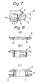
- FIG. 7 shows the condition of the engaging portion between the projections 4a on the eyelet body 1 and the engaging portions 8 on the seat plate 6 on an enlarged scale. Since the diameter R of the circle described by the outer surfaces of the projections 4a, 4b on the eyelet body 1 (Fig. 1) is slightly greater than the diameter r of the circle described by the inner surface of the engaging portions 8 on the seat plate 6 (Fig. 4), when the cylindrical portion 2 of the eyelet body 1 is pressed into the hole 11 in the seat plate 6, the engaging portions 8 on the seat plate 6 are deformed outwardly. The fabric 12 is pinched between the flange 3 of the eyelet body 1 and the outer peripheral portion of the seat plate 6.
- the cylindrical portion 2 of the eyelet body 1 is pressed into the hole 11 in the seat plate 6 until the detents 5 on the eyelet body 1 and the detents 10 on the seat plate 6 bite into the fabric 12 in different positions of the fabric 12 whereupon the corresponding projections 4a and engaging portions 8 engage each other and the deformed engaging portions regain their original shape whereby firm assembling of the eyelet body and seat plate is obtained.
- the lower projections 4b engage the engaging portions 8.
- the engaging portions 8 can engage with the lower projections 4b.
- the engaging portions 8 of the seat plate 6 can be made relatively thick.
- the lower projections 4b do not lie just below the upper projections 4a, the upper projections can be made relatively thick.
- the thickness of the engaging portions on the seat plate is limited by the narrow space between the upper and lower projections on the eyelet body and since the projections have a saw-tooth cross section, the tips of the engaging portions on the seat plate are necessarily pointed. Therefore, when the pitch of the projections is made fine, the strength of the engaging portions and the projections becomes insufficient and low which makes them fragile and makes it impossible to employ a fine pitch.
- each of the projections are provided symmetrically on the peripheral surface of the cylindrical portion of the eyelet body so that each projection extends by an angular distance which is less than a quarter of the circumference of the eyelet body, each of the projections are adapted to engage the engaging portions of the seat plate within a predetermined range, the projections in vertically adjacent levels are arranged so that they do not overlap each other vertically and each of the projections are adapted to engage different positions of the seat plate, the projections can engage the engaging portions even when the thickness of the projections and engaging portions is made large.
- each pair of arcuate projections 4a, 4a and 4b, 4b respectively includes two symmetrically disposed projections each extending by an angular distance of a quarter of the circumference of the cylindrical portion 2 of the eyelet body and such pairs of projections are disposed at two different levels so that they do not overlap vertically when viewed from the front side of the eyelet body
- the length of the arcuate projections may be shorter than a quarter of the circumference of the cylindrical portion of the eyelet body provided that the projections on the cylindrical portion are provided symmetrically and that the projections at the adjacent levels do not vertically overlap each other.
- the projections preferably have the same length to ensure a balanced engagement.
- the number of levels of projections can be varied in proportion to varying thicknesses of fabric as necessary.
- the eyelet body may be provided, as more clearly shown in Fig. 3, with arcuate projections at six different. levels in such an arrangement that each arcuate projection extends by an angular distance of one-sixth of the circumference about the cylindrical portion and the projections in adjacent levels do not overlap each other vertically.
- the seat plate shown in Figs. 4 and 5 may commonly be used as a seat plate.
Landscapes
- Engineering & Computer Science (AREA)
- General Engineering & Computer Science (AREA)
- Mechanical Engineering (AREA)
- Lining Or Joining Of Plastics Or The Like (AREA)
- Furniture Connections (AREA)
- Footwear And Its Accessory, Manufacturing Method And Apparatuses (AREA)
- Slide Fasteners, Snap Fasteners, And Hook Fasteners (AREA)
- Insertion Pins And Rivets (AREA)
- Connection Of Plates (AREA)
Abstract
Description
- This invention relates to an eyelet assembly including an eyelet body and a seat plate formed by plastic material which are adapted to be assembled together on a piece of fabric or the like.
- Heretofore, various types of plastic eyelet assemblies in which the eyelet body and the seat plate are assembled together by utilizing the inherent resilience of plastic material have been known. For instance, a typical example of such a prior art plastic eyelet assembly is disclosed in Japanese Utility Model Application Laid-Open No. 83904/79. As shown in Fig. 8, the eyelet assembly of this prior art includes the plastic seat plate A and plastic eyelet body B which is adapted to be fit in the seat plate A. The external peripheral surface of the cylindrical portion of the eyelet body B is provided with a plurality of annular horizontal projections C having a saw-tooth cross section in vertically spaced relationship. These projections are adapted to engage the engaging portion D formed at the inner edge of the annular seat plate A with fabric pinched between the flange of the eyelet body B and the seat plate A. The position at which the projections C engage with the engaging portion D may be changed depending on variations in the thickness of the fabric.
- In this prior art eyelet assembly referred to hereinabove, however, since the projections on the external peripheral surface of the cylindrical portion of the eyelet body are formed with a fully annular shape vertically spaced from each other, when the pitch of the projections is made fine, the thickness of the projections and also the engaging portion of the seat plate must accordingly be made thin. This reduces the strength of the projections and the engaging portion and leads to easy breakage of the same. In particular, when an eyelet assembly is adapted to be used for thin fabric, it is not possible to design the eyelet assembly in such a way that the engaging position between the projections and the engaging portion can be changed depending on variations in the thickness of the fabric, because the thickness of the porjections and the engaging portion must be made extraordinarily thin. Thus, the prior art eyelet assembly cannot fully exert its original perofm- ance in a thin fabric.
- Therefore, a primary object of the present invention is to provide an eyelet assembly which is applicable to a thin fabric by improving the shape and position of the projections on the external peripheral surface of the cylindrical portion of the eyelet body.
- In order to achieve the aforementioned object, the present invention is constructed as an eyelet assembly wherein a plurality of arcuate projections of a predetermined thickness are formed on the external peripheral surface of the cylindrical portion of the eyelet body vertically spaced from each other, each arcuate projection extending by an angular distance which is less than a quarter of the circumference of the cylindrical portion and the projections in vertically adjacent levels are staggered horizontally so that they do not overlap each other vertically when viewed from the front side of the eyelet body.
- According to the present invention, since the projections in the veritcally adjacent levels on the eyelet body are staggered horizontally so that they do not overlap vertically, the projections on the eyelet body as well as the engaging portions of the seat plate can be formed relatively thick and thus, even if the pitch of the projections on the eyelet body is made fine, the strength of the projections and the engaging portions will not be reduced. Thus, even when an eyelet assembly is constructed to be used for thin fabric, the eyelet body can be provided with fine pitched projections in such a way that the engaging position between the projection of the eyelet body and the engaging portion of the seat plate can be changed depending upon the thickness of the fabric to which the eyelet assembly is attached.
- Many other advantages and features of the present invention will become apparent to those skilled in the art upon making reference to the detailed description and the accompanying drawings in which a preferred embodiment incorporating the principles of the present invention is shown by way of illustrative example.
- Fig. 1 is an elevational view of a first embodiment of the eyelet body according to the present invention with the left half in section;
- Fig. 2 is a bottom plan view of said eyelet body;
- Fig. 3 is an elevational view of a second embodiment of the eyelet body according to the present invention;
- Fig. 4 is an elevational view in vertical section of the seat plate to be assembled with the eyelet body taken along the line IV - IV of Fig. 5;
- Fig. 5 is a bottom plan view of the seat plate of Fig. 4;
- Fig. 6 is an elevational view showing the eyelet assembly when being attached to a piece of fabric;
- Fig. 7 is a fragmentary elevational view on an enlarged scale showing the engaging portion between the eyelet body and seat plate as shown in Fig. 6;
- Fig. 8A is an elevational view in vertical section of the seat plate for a prior art eyelet assembly;
- Fig. 8B is an elevational view in left half section of the eyelet body for said prior art eyelet assembly; and
- Fig. 8C is an elevational view in section of the assembly of the seat plate and eyelet body as shown in Figs. 8A and 8B, respectively.
- Referring to the accompanying drawings and more particularly to Figs. 1 and 2 thereof in which the first embodiment of the eyelet assembly according to the present invention is shown, the eyelet body 1 is formed of soft plastic such as
Nylon 6 and comprises a hollowcylindrical portion 2 and aflange 3 extending radially outwardly from the upper end of the cylindrical portion. As more clearly shown in Fig. 2, the undersurface of theflange 3 is formed with fourdetents 5 in an equally spaced relationship in the circumferential direction of the flange so that when the eyelet body 1 is assembled with a seat plate 6 (which will be described hereinbelow), thedetents 5 bite into the fabric to thereby prevent the eyelet body from rotating relative to the fabric. Also as more clearly shown in Fig. 2, a first pair of outwardly extending and diametricallyopposing projections cylindrical portion 2 each covering the angular distance of a quarter of the circumference of the cylindrical portion and similarly, a second pair of outwardly extending and diametricallyopposing projections cylindrical portion 2 each covering the angular distance of a quarter of the circumference of the cylindrical portion. - These first and second pairs of
projections projections projections - The
seat plate 6 is formed of hard plastic such as polybutylene terephtalate (PBT) and as more clearly shown in Figs. 4 and 5, theseat plate 6 is formed with acenter hole 11 in which thecylindrical portion 2 of the eyelet body 1 is fitted. As more clearly shown in Fig. 5, the inner peripheral edge of thehole 11 is formed with four equally spacedengaging portions 8 separated by recesses therebetween and having a uniform thickness and the outerperipheral portion 7 of theseat plate 6 is formed with four arcuate grooves 9 corresponding to theengaging portions 8 in position (Fig. 4) to impart resilient flexibility to theengaging portions 8. Provided on theseat plate 6 outside of the grooves 9 are fourdetents 10 displaced relative to thedetents 5 on the eyelet body 1 so that thedetents 10 do not lie on thedetents 5 when the eyelet body and seat plate are assembled together. - When the eyelet body 1 and
seat plate 6 are to be attached tofabric 12, first of all, thefabric 12 is formed with a circular hole (not shown) in a selected position where the eyelet body and seat plate are to be attached. The hole has a diameter slightly smaller than the outer diameter of thecylindrical portion 2 of the eyelet body 1. Theseat plate 6 is placed under the circular hole in thefabric 12 and thecylindrical portion 2 of the eyelet body 1 is pressed through the circular hole in thefabric 12 into thehole 11 in theseat plate 6 until the projections of the eyelet body 1 engage theengaging portions 8 on theseat plate 6 to thereby attach the eyelet assembly to thefabric 12 as shown in Fig. 6. Fig. 7 shows the condition of the engaging portion between theprojections 4a on the eyelet body 1 and theengaging portions 8 on theseat plate 6 on an enlarged scale. Since the diameter R of the circle described by the outer surfaces of theprojections engaging portions 8 on the seat plate 6 (Fig. 4), when thecylindrical portion 2 of the eyelet body 1 is pressed into thehole 11 in theseat plate 6, theengaging portions 8 on theseat plate 6 are deformed outwardly. Thefabric 12 is pinched between theflange 3 of the eyelet body 1 and the outer peripheral portion of theseat plate 6. Thecylindrical portion 2 of the eyelet body 1 is pressed into thehole 11 in theseat plate 6 until thedetents 5 on the eyelet body 1 and thedetents 10 on theseat plate 6 bite into thefabric 12 in different positions of thefabric 12 whereupon thecorresponding projections 4a and engagingportions 8 engage each other and the deformed engaging portions regain their original shape whereby firm assembling of the eyelet body and seat plate is obtained. When thefabric 12 is relatively thick, thelower projections 4b engage theengaging portions 8. As seen on the left-hand side of Fig. 6, since theupper projections 4a do not lie just above thelower projections 4b, even when theengaging portions 8 are formed relatively thick, theengaging portions 8 can engage with thelower projections 4b. Thus, even when the distance or pitch between the upper andlower projections engaging portions 8 of theseat plate 6 can be made relatively thick. And since thelower projections 4b do not lie just below theupper projections 4a, the upper projections can be made relatively thick. In the conventional eyelet assembly, the thickness of the engaging portions on the seat plate is limited by the narrow space between the upper and lower projections on the eyelet body and since the projections have a saw-tooth cross section, the tips of the engaging portions on the seat plate are necessarily pointed. Therefore, when the pitch of the projections is made fine, the strength of the engaging portions and the projections becomes insufficient and low which makes them fragile and makes it impossible to employ a fine pitch. - As mentioned hereinabove, according to the present invention, since the projections are provided symmetrically on the peripheral surface of the cylindrical portion of the eyelet body so that each projection extends by an angular distance which is less than a quarter of the circumference of the eyelet body, each of the projections are adapted to engage the engaging portions of the seat plate within a predetermined range, the projections in vertically adjacent levels are arranged so that they do not overlap each other vertically and each of the projections are adapted to engage different positions of the seat plate, the projections can engage the engaging portions even when the thickness of the projections and engaging portions is made large.
- Although, in the embodiment shown in Figs. 1 and 2, each pair of
arcuate projections cylindrical portion 2 of the eyelet body and such pairs of projections are disposed at two different levels so that they do not overlap vertically when viewed from the front side of the eyelet body, the length of the arcuate projections may be shorter than a quarter of the circumference of the cylindrical portion of the eyelet body provided that the projections on the cylindrical portion are provided symmetrically and that the projections at the adjacent levels do not vertically overlap each other. The projections preferably have the same length to ensure a balanced engagement. The number of levels of projections can be varied in proportion to varying thicknesses of fabric as necessary. For example, in order to provide an eyelet assembly which can accommodate six different fabric thicknesses, the eyelet body may be provided, as more clearly shown in Fig. 3, with arcuate projections at six different. levels in such an arrangement that each arcuate projection extends by an angular distance of one-sixth of the circumference about the cylindrical portion and the projections in adjacent levels do not overlap each other vertically. In this case, as a seat plate, the seat plate shown in Figs. 4 and 5 may commonly be used.
Claims (10)
Applications Claiming Priority (2)
| Application Number | Priority Date | Filing Date | Title |
|---|---|---|---|
| JP161894/84 | 1984-10-26 | ||
| JP1984161894U JPS635548Y2 (en) | 1984-10-26 | 1984-10-26 |
Publications (2)
| Publication Number | Publication Date |
|---|---|
| EP0179367A2 true EP0179367A2 (en) | 1986-04-30 |
| EP0179367A3 EP0179367A3 (en) | 1986-12-30 |
Family
ID=15744027
Family Applications (1)
| Application Number | Title | Priority Date | Filing Date |
|---|---|---|---|
| EP85112919A Ceased EP0179367A3 (en) | 1984-10-26 | 1985-10-11 | Eyelet assembly |
Country Status (8)
| Country | Link |
|---|---|
| US (1) | US4664574A (en) |
| EP (1) | EP0179367A3 (en) |
| JP (1) | JPS635548Y2 (en) |
| KR (1) | KR870001690Y1 (en) |
| BR (1) | BR8505405A (en) |
| ES (1) | ES289880Y (en) |
| GB (1) | GB2166510A (en) |
| ZA (1) | ZA857573B (en) |
Cited By (3)
| Publication number | Priority date | Publication date | Assignee | Title |
|---|---|---|---|---|
| EP0366401A1 (en) * | 1988-10-27 | 1990-05-02 | Hako Minuteman, Inc. | Holder for rotary pad |
| EP2618005A1 (en) * | 2012-01-20 | 2013-07-24 | Profil Verbindungstechnik GmbH & Co. KG | Combination of functional element and pressure plate |
| IT201700073268A1 (en) * | 2017-06-30 | 2018-12-30 | Emanuele Tua | GUIDE DEVICE FOR PASSING WHEELS THROUGH TUBULAR SUPPORTS OF SAILING BOATS, PARTICULARLY SHAFTS AND BOMA, AND TUBULAR SUPPORT USING THIS DEVICE. |
Families Citing this family (21)
| Publication number | Priority date | Publication date | Assignee | Title |
|---|---|---|---|---|
| US4878792A (en) * | 1988-08-01 | 1989-11-07 | Illinois Tool Works, Inc. | Removable mat fastener |
| USD337255S (en) | 1990-05-22 | 1993-07-13 | Novelli Sr Frank J | Grommet |
| CA2124165C (en) * | 1994-05-24 | 1998-10-13 | Young Sup Lee | Plastic eyelet |
| KR200209457Y1 (en) * | 1998-06-12 | 2001-01-15 | 권석웅 | Awning eyelets |
| JP4493210B2 (en) * | 2000-12-27 | 2010-06-30 | ポップリベット・ファスナー株式会社 | Mat fixture |
| JP5002095B2 (en) * | 2001-07-17 | 2012-08-15 | アイリスオーヤマ株式会社 | Connecting structure for connecting the column to the wooden board |
| GB2403784B (en) * | 2003-07-08 | 2006-05-03 | Bandex Verwaltungs Gmbh | Eyelets |
| US7455192B2 (en) | 2004-11-03 | 2008-11-25 | Illinois Tool Works Inc. | Overmolded adhesive hole plug |
| US20080052878A1 (en) * | 2006-08-31 | 2008-03-06 | Lewis Jeffrey C | Fastener Clip with Seal |
| DE102009016633A1 (en) * | 2008-11-26 | 2010-05-27 | Illinois Tool Works Inc., Glenview | Fastening means for pre-assembly of a pin-shaped connecting means in a passage opening of a component |
| DE102011052190A1 (en) * | 2011-07-27 | 2013-01-31 | Böllhoff Verbindungstechnik GmbH | Plug-in coupling and method for its production |
| KR101139106B1 (en) * | 2012-01-12 | 2012-04-30 | 이성환 | Eyelet |
| KR101684606B1 (en) | 2015-04-23 | 2016-12-08 | 유승민 | Eyelet device and producing method thereof |
| WO2016171417A2 (en) * | 2015-04-23 | 2016-10-27 | 유승민 | Eyelet member and method of manufacturing same |
| USD837685S1 (en) * | 2016-12-20 | 2019-01-08 | Morito Co., Ltd. | Eyelet |
| KR102053436B1 (en) * | 2018-07-05 | 2019-12-06 | 유충한 | Eyelet |
| USD891294S1 (en) * | 2018-11-16 | 2020-07-28 | Hyuck Sang Jo | Eyelet |
| USD891293S1 (en) * | 2018-11-16 | 2020-07-28 | Hyuck Sang Jo | Eyelet |
| US11155189B2 (en) | 2020-02-13 | 2021-10-26 | Honda Motor Co., Ltd. | Bumper assembly for vehicle seat |
| US11161580B1 (en) | 2020-05-27 | 2021-11-02 | Henry Sanders | Roller assisted low friction reefing grommet |
| WO2026029719A1 (en) * | 2024-07-29 | 2026-02-05 | Vetaş Plasti̇k Ve Ambalaj Sanayi̇ Anoni̇m Şi̇rketi̇ | Drawstring sack and bag |
Family Cites Families (11)
| Publication number | Priority date | Publication date | Assignee | Title |
|---|---|---|---|---|
| US382921A (en) * | 1888-05-15 | Sail-groivimet | ||
| GB748948A (en) * | 1953-04-01 | 1956-05-16 | Baker & Finnemore Ltd | Improvements in or relating to retaining devices |
| US3091795A (en) * | 1960-08-05 | 1963-06-04 | Gilbert G Budwig | Grommet |
| US3049777A (en) * | 1960-11-04 | 1962-08-21 | United Carr Fastener Corp | Two-piece plastic stud |
| GB1128227A (en) * | 1965-10-18 | 1968-09-25 | Heyman Mfg Company | Self-locking grommet |
| GB1185275A (en) * | 1968-04-30 | 1970-03-25 | George Fritzmeier Kg | Improvements in and relating to Plug and Socket Connections of Plastics Material |
| CH537715A (en) * | 1971-05-04 | 1973-06-15 | Textima Co Ltd | Lockable push button |
| US3810279A (en) * | 1973-02-28 | 1974-05-14 | Illinois Tool Works | Plastic drive fastener |
| DE2364423A1 (en) * | 1973-12-22 | 1975-06-26 | Gerald Gliemann | CLOSURE FOR CLOTHING |
| US4396329A (en) * | 1981-01-26 | 1983-08-02 | Phillips Plastics Corporation | Pine tree clip |
| JPS57129410U (en) * | 1981-02-06 | 1982-08-12 |
-
1984
- 1984-10-26 JP JP1984161894U patent/JPS635548Y2/ja not_active Expired
-
1985
- 1985-10-01 ZA ZA857573A patent/ZA857573B/en unknown
- 1985-10-03 US US06/784,455 patent/US4664574A/en not_active Expired - Fee Related
- 1985-10-11 EP EP85112919A patent/EP0179367A3/en not_active Ceased
- 1985-10-15 GB GB08525395A patent/GB2166510A/en not_active Withdrawn
- 1985-10-17 KR KR2019850013525U patent/KR870001690Y1/en not_active Expired
- 1985-10-21 BR BR8505405A patent/BR8505405A/en unknown
- 1985-10-25 ES ES1985289880U patent/ES289880Y/en not_active Expired
Cited By (4)
| Publication number | Priority date | Publication date | Assignee | Title |
|---|---|---|---|---|
| EP0366401A1 (en) * | 1988-10-27 | 1990-05-02 | Hako Minuteman, Inc. | Holder for rotary pad |
| EP2618005A1 (en) * | 2012-01-20 | 2013-07-24 | Profil Verbindungstechnik GmbH & Co. KG | Combination of functional element and pressure plate |
| US9151312B2 (en) | 2012-01-20 | 2015-10-06 | Profil Verbindungstechnik Gmbh & Co. Kg | Combination of functional element and pressure plate |
| IT201700073268A1 (en) * | 2017-06-30 | 2018-12-30 | Emanuele Tua | GUIDE DEVICE FOR PASSING WHEELS THROUGH TUBULAR SUPPORTS OF SAILING BOATS, PARTICULARLY SHAFTS AND BOMA, AND TUBULAR SUPPORT USING THIS DEVICE. |
Also Published As
| Publication number | Publication date |
|---|---|
| EP0179367A3 (en) | 1986-12-30 |
| GB2166510A (en) | 1986-05-08 |
| US4664574A (en) | 1987-05-12 |
| JPS635548Y2 (en) | 1988-02-16 |
| ZA857573B (en) | 1986-06-25 |
| ES289880U (en) | 1986-04-01 |
| KR870001690Y1 (en) | 1987-05-13 |
| ES289880Y (en) | 1986-11-16 |
| GB8525395D0 (en) | 1985-11-20 |
| BR8505405A (en) | 1986-08-05 |
| JPS6177806U (en) | 1986-05-24 |
| KR860004274U (en) | 1986-05-01 |
Similar Documents
| Publication | Publication Date | Title |
|---|---|---|
| US4664574A (en) | Eyelet assembly | |
| US5026323A (en) | Structure for mounting boot | |
| EP0081148B1 (en) | Snap fastener for use on garments | |
| US5702133A (en) | Universal snap-in metal plug | |
| EP0251516B1 (en) | Seal assembly for a fastener | |
| CA2215706C (en) | Improved slant coil spring and seal | |
| US2675844A (en) | Lock washer | |
| US3304796A (en) | Plastic hub and insert assembly for wheels and sprockets | |
| JPH0774648B2 (en) | Spacing retainer | |
| JPH04219509A (en) | Screw grommet made of plastic | |
| JPS6123425B2 (en) | ||
| US5417512A (en) | End connector with captive ball and bearing half with crushed elements | |
| US4613239A (en) | Solid window cage for cylindrical roller bearing | |
| US4050120A (en) | Fastener | |
| US5188476A (en) | Ball joint | |
| US5470165A (en) | Retaining bushing for joining bearing rings | |
| GB2186536A (en) | Steering wheel | |
| CA1045398A (en) | Apparatus for holding knobs | |
| GB2066591A (en) | Electrical connector shell and method of making same | |
| US3084962A (en) | Fastener means | |
| EP0080697A1 (en) | Grommet | |
| US3868099A (en) | Annularly resilient, conically shaped component | |
| US3215025A (en) | Push-on retainers | |
| JPS60488Y2 (en) | Synthetic resin snap spring | |
| CN215762709U (en) | Screw nail |
Legal Events
| Date | Code | Title | Description |
|---|---|---|---|
| PUAI | Public reference made under article 153(3) epc to a published international application that has entered the european phase |
Free format text: ORIGINAL CODE: 0009012 |
|
| AK | Designated contracting states |
Kind code of ref document: A2 Designated state(s): BE CH DE FR IT LI NL SE |
|
| PUAL | Search report despatched |
Free format text: ORIGINAL CODE: 0009013 |
|
| AK | Designated contracting states |
Kind code of ref document: A3 Designated state(s): BE CH DE FR IT LI NL SE |
|
| 17P | Request for examination filed |
Effective date: 19870330 |
|
| 17Q | First examination report despatched |
Effective date: 19880406 |
|
| STAA | Information on the status of an ep patent application or granted ep patent |
Free format text: STATUS: THE APPLICATION HAS BEEN REFUSED |
|
| 18R | Application refused |
Effective date: 19880925 |
|
| RIN1 | Information on inventor provided before grant (corrected) |
Inventor name: KASAI, KAZUMI |