EP0179282B1 - Verfahren zur zentralen Gewinnung eines der Fahrzeuggeschwindigkeit angenäherten Bezugssignals - Google Patents
Verfahren zur zentralen Gewinnung eines der Fahrzeuggeschwindigkeit angenäherten Bezugssignals Download PDFInfo
- Publication number
- EP0179282B1 EP0179282B1 EP19850111979 EP85111979A EP0179282B1 EP 0179282 B1 EP0179282 B1 EP 0179282B1 EP 19850111979 EP19850111979 EP 19850111979 EP 85111979 A EP85111979 A EP 85111979A EP 0179282 B1 EP0179282 B1 EP 0179282B1
- Authority
- EP
- European Patent Office
- Prior art keywords
- microprocessors
- reference signal
- microprocessor
- processor
- code number
- Prior art date
- Legal status (The legal status is an assumption and is not a legal conclusion. Google has not performed a legal analysis and makes no representation as to the accuracy of the status listed.)
- Expired - Lifetime
Links
- 238000000034 method Methods 0.000 title claims description 9
- 238000005259 measurement Methods 0.000 claims 1
- 238000012544 monitoring process Methods 0.000 claims 1
- 230000005540 biological transmission Effects 0.000 abstract description 3
- 238000010586 diagram Methods 0.000 description 2
- 230000001133 acceleration Effects 0.000 description 1
- 230000015572 biosynthetic process Effects 0.000 description 1
Images
Classifications
-
- B—PERFORMING OPERATIONS; TRANSPORTING
- B60—VEHICLES IN GENERAL
- B60T—VEHICLE BRAKE CONTROL SYSTEMS OR PARTS THEREOF; BRAKE CONTROL SYSTEMS OR PARTS THEREOF, IN GENERAL; ARRANGEMENT OF BRAKING ELEMENTS ON VEHICLES IN GENERAL; PORTABLE DEVICES FOR PREVENTING UNWANTED MOVEMENT OF VEHICLES; VEHICLE MODIFICATIONS TO FACILITATE COOLING OF BRAKES
- B60T8/00—Arrangements for adjusting wheel-braking force to meet varying vehicular or ground-surface conditions, e.g. limiting or varying distribution of braking force
- B60T8/17—Using electrical or electronic regulation means to control braking
- B60T8/172—Determining control parameters used in the regulation, e.g. by calculations involving measured or detected parameters
-
- Y—GENERAL TAGGING OF NEW TECHNOLOGICAL DEVELOPMENTS; GENERAL TAGGING OF CROSS-SECTIONAL TECHNOLOGIES SPANNING OVER SEVERAL SECTIONS OF THE IPC; TECHNICAL SUBJECTS COVERED BY FORMER USPC CROSS-REFERENCE ART COLLECTIONS [XRACs] AND DIGESTS
- Y10—TECHNICAL SUBJECTS COVERED BY FORMER USPC
- Y10S—TECHNICAL SUBJECTS COVERED BY FORMER USPC CROSS-REFERENCE ART COLLECTIONS [XRACs] AND DIGESTS
- Y10S303/00—Fluid-pressure and analogous brake systems
- Y10S303/09—Plural processors
Definitions
- the invention relates to a method for the central acquisition of a reference signal approximated in the course of the vehicle speed according to the preamble of claim 1.
- the inventive solution according to claim 1 has the essential advantage over the prior art that wheel speeds do not have to be transmitted from the microprocessors for the central acquisition of the reference signal. Rather, the other microprocessors only transmit code numbers, i.e. short digital words, to the reference processor. According to claim 1, the reference processor transmits only the reference signal to the other microprocessors. If the method according to claim 1 is supplemented by the features of claims 2 to 4, it is ensured that transmission errors are recognized.
- the method according to the invention can be used in the case of anti-lock regulators, insofar as slip is included in the regulation, as well as in traction slip rules.
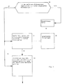
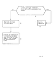
- FIG. 3 and 4 flow diagrams relating to the reference processor (Fig.3) and the other microprocessors (Fig. 4).
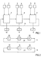
- Fig. 1 are designated 1-6 transducers and transducers, the digital signals corresponding to the wheel speeds microprocessors 7-9 for processing to brake pressure control signals for the solenoid valves 10-12 (1 axis per valve). There the wheel slip is determined and wheel acceleration and wheel deceleration signals are formed in a known manner and processed into brake pressure control signals.
- a reference signal approximated in the course of the vehicle speed is required. This is to be calculated here in the microprocessor 8, which is also to include the reference processor here.
- the microprocessors 7-9 are switched into a ring line 13. Based on the determination of whether the reference signal is smaller than the assigned wheel speed signal or larger or how the associated valve is driven, it is proposed in the individual microprocessors 7-9 whether a positive slope, a large negative slope or a small negative slope for the change the reference signal is attached from the point of view of the individual microprocessor. A code number consisting of just a few characters is assigned to the desired slope determined. A priority order of the possible gradients is defined in the microprocessor 8.
- Each reference signal is supplied to the microprocessors which are involved in the formation of this reference signal by their proposal.
- microprocessors conventional devices such. B. ⁇ P Motorola 6801 U4 or Intel 8051 can be used.
- FIG. 3 shows a possible flow diagram for the reference processor 8 of FIG. 1.
- a block 30 it is determined whether the received reference signal corresponds to the reference signal previously given to the ring line. If this is the case, the data telegram is routed to block 31, which is connected to a further block 32, in which the possible gradients are stored in a given priority order and are identified by code numbers.
- block 31 in conjunction with block 32 it is now determined which of the slope suggestions received as code numbers has the highest priority. The result is reported via a line 34 to a block 33, to which the data telegram is likewise fed via a line 35. Starting from the last calculated reference signal, the proposed slope of highest priority and the cycle time of the microprocessor are used in block 33 to calculate the new reference signal and insert it in the data telegram for the previous reference signal. The data telegram is then sent.
- the subsequent microprocessor 9 checks in an input stage (40 in FIG. 4) whether the slope suggestion made by microprocessor 9 in the previous cycle in the form of a code number matches the corresponding suggestion in the data message or whether the data message is garbled.
- the new reference signal in the data telegram is noted in block 41 and used for further slip determination.
- the slope proposal (code number A) of the microprocessor 9 from the previous cycle is replaced by a new proposal with the code number A 'in the data telegram.
- the changed data telegram is then forwarded via the ring line to the microprocessor 7, where the procedure is exactly the same.
- Blocks 36 and 43 indicate when the received reference signal or the received code number does not match the previously transmitted data word.
Landscapes
- Engineering & Computer Science (AREA)
- Transportation (AREA)
- Mechanical Engineering (AREA)
- Regulating Braking Force (AREA)
- Electric Propulsion And Braking For Vehicles (AREA)
- Train Traffic Observation, Control, And Security (AREA)
Priority Applications (1)
| Application Number | Priority Date | Filing Date | Title |
|---|---|---|---|
| AT85111979T ATE66647T1 (de) | 1984-09-29 | 1985-09-21 | Verfahren zur zentralen gewinnung eines der fahrzeuggeschwindigkeit angenaeherten bezugssignals. |
Applications Claiming Priority (2)
| Application Number | Priority Date | Filing Date | Title |
|---|---|---|---|
| DE3435864 | 1984-09-29 | ||
| DE19843435864 DE3435864A1 (de) | 1984-09-29 | 1984-09-29 | Verfahren zur zentralen gewinnung eines im verlauf der fahrzeuggeschwindigkeit angenaeherten bezugssignals |
Publications (3)
| Publication Number | Publication Date |
|---|---|
| EP0179282A2 EP0179282A2 (de) | 1986-04-30 |
| EP0179282A3 EP0179282A3 (en) | 1989-07-19 |
| EP0179282B1 true EP0179282B1 (de) | 1991-08-28 |
Family
ID=6246732
Family Applications (1)
| Application Number | Title | Priority Date | Filing Date |
|---|---|---|---|
| EP19850111979 Expired - Lifetime EP0179282B1 (de) | 1984-09-29 | 1985-09-21 | Verfahren zur zentralen Gewinnung eines der Fahrzeuggeschwindigkeit angenäherten Bezugssignals |
Country Status (5)
| Country | Link |
|---|---|
| US (1) | US4629259A (enExample) |
| EP (1) | EP0179282B1 (enExample) |
| JP (1) | JPS6185250A (enExample) |
| AT (1) | ATE66647T1 (enExample) |
| DE (2) | DE3435864A1 (enExample) |
Families Citing this family (13)
| Publication number | Priority date | Publication date | Assignee | Title |
|---|---|---|---|---|
| US4971401A (en) * | 1986-07-31 | 1990-11-20 | Nippon A B S, Ltd. | Anti-skid control apparatus for braking system |
| DE3833212A1 (de) * | 1988-09-30 | 1990-04-05 | Bosch Gmbh Robert | Antiblockierregelsystem |
| DE3841956A1 (de) * | 1988-12-14 | 1990-06-21 | Bosch Gmbh Robert | Antiblockierregelsystem |
| DE8910805U1 (de) * | 1989-09-09 | 1991-01-10 | Robert Bosch Gmbh, 7000 Stuttgart | Elektrische Verbindungsvorrichtung |
| JP2874224B2 (ja) * | 1989-11-16 | 1999-03-24 | アイシン精機株式会社 | アンチスキツド制御装置 |
| DE4022671A1 (de) * | 1990-07-17 | 1992-01-23 | Wabco Westinghouse Fahrzeug | Elektronisches bremssystem fuer stassenfahrzeuge |
| DE4037143A1 (de) * | 1990-11-22 | 1992-05-27 | Bosch Gmbh Robert | Steuerungssystem |
| US5265944A (en) * | 1991-09-23 | 1993-11-30 | Allied-Signal, Inc. | Wheel speed verification system |
| US5193886A (en) * | 1991-09-23 | 1993-03-16 | Allied-Signal Inc. | Wheel speed verification system |
| DE4439060A1 (de) * | 1994-11-02 | 1996-05-09 | Teves Gmbh Alfred | Mikroprozessoranordnung für ein Fahrzeug-Regelungssystem |
| DE19643013C1 (de) * | 1996-10-18 | 1998-02-12 | Telefunken Microelectron | Datenübertragungssystem |
| US6438273B1 (en) * | 1998-12-23 | 2002-08-20 | Xerox Corporation | Method and apparatus for using rotatable templates within look-up tables to enhance image reproduction |
| DE102011004090A1 (de) | 2011-02-14 | 2012-08-16 | Lear Corporation | Sitz-Lehnenvorrichtung mit koaxialer Easy-Entry-Löseeinrichtung |
Family Cites Families (2)
| Publication number | Priority date | Publication date | Assignee | Title |
|---|---|---|---|---|
| DE2558712C2 (de) * | 1975-12-24 | 1987-04-16 | Robert Bosch Gmbh, 7000 Stuttgart | Antiblockierregelsystem |
| US4338669A (en) * | 1980-05-07 | 1982-07-06 | Crane Co. | Modulator for anti-skid braking system |
-
1984
- 1984-09-29 DE DE19843435864 patent/DE3435864A1/de active Granted
-
1985
- 1985-09-21 DE DE8585111979T patent/DE3583915D1/de not_active Expired - Lifetime
- 1985-09-21 EP EP19850111979 patent/EP0179282B1/de not_active Expired - Lifetime
- 1985-09-21 AT AT85111979T patent/ATE66647T1/de not_active IP Right Cessation
- 1985-09-26 US US06/780,396 patent/US4629259A/en not_active Expired - Fee Related
- 1985-09-27 JP JP60212774A patent/JPS6185250A/ja active Pending
Also Published As
| Publication number | Publication date |
|---|---|
| DE3583915D1 (de) | 1991-10-02 |
| EP0179282A2 (de) | 1986-04-30 |
| DE3435864C2 (enExample) | 1993-01-07 |
| JPS6185250A (ja) | 1986-04-30 |
| US4629259A (en) | 1986-12-16 |
| DE3435864A1 (de) | 1986-04-10 |
| EP0179282A3 (en) | 1989-07-19 |
| ATE66647T1 (de) | 1991-09-15 |
Similar Documents
| Publication | Publication Date | Title |
|---|---|---|
| EP0179282B1 (de) | Verfahren zur zentralen Gewinnung eines der Fahrzeuggeschwindigkeit angenäherten Bezugssignals | |
| EP0216372B1 (de) | Datenbussystem für Fahrzeuge | |
| DE102019002790B4 (de) | Verfahren zur Prädiktion einer Verkehrssituation für ein Fahrzeug | |
| DE2943149C2 (de) | Ringnetzwerk mit mehreren an eine Daten-Ringleitung angeschlossenen Prozessoren | |
| DE102015220481B4 (de) | Verfahren und Vorrichtung in einer Verkehrseinheit zum kooperativen Abstimmen von Fahrmanövern von mindestens zwei Kraftfahrzeugen | |
| DE102010054077A1 (de) | Verfahren und Vorrichtung zum Bereitstellen einer Fahrempfehlung für einen Streckenabschnitt | |
| EP0108969A2 (de) | DMA-Steuereinrichtung zur Übertragung von Daten zwischen einem Datensender und einem Datenempfänger | |
| EP0035731A2 (de) | Verfahren und Anordnung zum Übertragen von Datensignalen | |
| EP0784820B1 (de) | Vorrichtung und verfahren zur steuerung eines datenbusses | |
| DE3018576C2 (enExample) | ||
| DE1424747A1 (de) | Datenverarbeitungsanlage | |
| EP1455976A2 (de) | Maulweitenregelung an segmenten für stranggie anlagen | |
| DE102019115896A1 (de) | Begrenzte zeitsteuerungsanalyse von fahrzeuginterner kommunikation | |
| DE102017101505A1 (de) | Verfahren zum Betrieb von Schienenfahrzeugen | |
| EP2196372B1 (de) | Verfahren zum Steuern einer Beschleunigungseinrichtung für Kraftfahrzeuge | |
| DE19502230C2 (de) | Fuzzy-Regler für ein technisches System | |
| EP0551972B1 (de) | Einrichtung zur Zugbeeinflussung im Eisenbahnwesen | |
| DE3204098A1 (de) | Schaltungsanordnung zur ausgabe von steuerinformationen | |
| EP4389469B1 (de) | Verfahren zum zuordnen von reifendrucküberwachungseinheiten eines reifendrucküberwachungssystems eines fahrzeugs zu den positionen der räder an dem fahrzeug | |
| DE1914576C3 (de) | Programmgesteuerte Datenverar beitungsanlage, insbesondere fur die Abwicklung von Vermittlungsvorgangen in einer Fernsprechvermittlung | |
| EP0032581A2 (de) | Einrichtung zum Bestimmen des an ein Eisenbahn-Triebfahrzeug zu übertragenden Signalbegriffes | |
| DE102023002180A1 (de) | Verfahren zur Erstellung einer Verbrauchsmatrix für ein Fahrzeug | |
| DE102022210901A1 (de) | Verfahren und Steuerungseinrichtung zum Übertragen von Nachrichten mittels Fahrzeug-zu-Fahrzeug-Kommunikation | |
| DE102015106199B4 (de) | Verfahren zur Bestimmung von Sollwerten eines technischen Systems, technisches System sowie Computerprogramm | |
| EP0048939A1 (de) | Signalübertragungseinrichtung mit Stationen, die mit Eingabeeinrichtungen wahlweise bestückbar sind |
Legal Events
| Date | Code | Title | Description |
|---|---|---|---|
| PUAI | Public reference made under article 153(3) epc to a published international application that has entered the european phase |
Free format text: ORIGINAL CODE: 0009012 |
|
| AK | Designated contracting states |
Kind code of ref document: A2 Designated state(s): AT CH DE FR GB IT LI SE |
|
| PUAL | Search report despatched |
Free format text: ORIGINAL CODE: 0009013 |
|
| AK | Designated contracting states |
Kind code of ref document: A3 Designated state(s): AT CH DE FR GB IT LI SE |
|
| 17P | Request for examination filed |
Effective date: 19890810 |
|
| 17Q | First examination report despatched |
Effective date: 19901127 |
|
| GRAA | (expected) grant |
Free format text: ORIGINAL CODE: 0009210 |
|
| AK | Designated contracting states |
Kind code of ref document: B1 Designated state(s): AT CH DE FR GB IT LI SE |
|
| REF | Corresponds to: |
Ref document number: 66647 Country of ref document: AT Date of ref document: 19910915 Kind code of ref document: T |
|
| REF | Corresponds to: |
Ref document number: 3583915 Country of ref document: DE Date of ref document: 19911002 |
|
| ITF | It: translation for a ep patent filed | ||
| ET | Fr: translation filed | ||
| GBT | Gb: translation of ep patent filed (gb section 77(6)(a)/1977) | ||
| RAP4 | Party data changed (patent owner data changed or rights of a patent transferred) |
Owner name: ROBERT BOSCH GMBH |
|
| PLBE | No opposition filed within time limit |
Free format text: ORIGINAL CODE: 0009261 |
|
| STAA | Information on the status of an ep patent application or granted ep patent |
Free format text: STATUS: NO OPPOSITION FILED WITHIN TIME LIMIT |
|
| 26N | No opposition filed | ||
| PGFP | Annual fee paid to national office [announced via postgrant information from national office to epo] |
Ref country code: AT Payment date: 19920825 Year of fee payment: 8 |
|
| PGFP | Annual fee paid to national office [announced via postgrant information from national office to epo] |
Ref country code: SE Payment date: 19920904 Year of fee payment: 8 |
|
| PGFP | Annual fee paid to national office [announced via postgrant information from national office to epo] |
Ref country code: GB Payment date: 19920911 Year of fee payment: 8 |
|
| PGFP | Annual fee paid to national office [announced via postgrant information from national office to epo] |
Ref country code: CH Payment date: 19921218 Year of fee payment: 8 |
|
| PG25 | Lapsed in a contracting state [announced via postgrant information from national office to epo] |
Ref country code: GB Effective date: 19930921 Ref country code: AT Effective date: 19930921 |
|
| PG25 | Lapsed in a contracting state [announced via postgrant information from national office to epo] |
Ref country code: SE Effective date: 19930922 |
|
| PG25 | Lapsed in a contracting state [announced via postgrant information from national office to epo] |
Ref country code: LI Effective date: 19930930 Ref country code: CH Effective date: 19930930 |
|
| GBPC | Gb: european patent ceased through non-payment of renewal fee |
Effective date: 19930921 |
|
| REG | Reference to a national code |
Ref country code: CH Ref legal event code: PL |
|
| EUG | Se: european patent has lapsed |
Ref document number: 85111979.2 Effective date: 19940410 |
|
| PGFP | Annual fee paid to national office [announced via postgrant information from national office to epo] |
Ref country code: FR Payment date: 19950918 Year of fee payment: 11 |
|
| PGFP | Annual fee paid to national office [announced via postgrant information from national office to epo] |
Ref country code: DE Payment date: 19951127 Year of fee payment: 11 |
|
| PG25 | Lapsed in a contracting state [announced via postgrant information from national office to epo] |
Ref country code: FR Effective date: 19960930 |
|
| PG25 | Lapsed in a contracting state [announced via postgrant information from national office to epo] |
Ref country code: DE Effective date: 19970603 |
|
| REG | Reference to a national code |
Ref country code: FR Ref legal event code: ST |
|
| REG | Reference to a national code |
Ref country code: FR Ref legal event code: ST |