EP0179213A1 - Dispositif optique de déviation d'un faisceau laser - Google Patents
Dispositif optique de déviation d'un faisceau laser Download PDFInfo
- Publication number
- EP0179213A1 EP0179213A1 EP85109967A EP85109967A EP0179213A1 EP 0179213 A1 EP0179213 A1 EP 0179213A1 EP 85109967 A EP85109967 A EP 85109967A EP 85109967 A EP85109967 A EP 85109967A EP 0179213 A1 EP0179213 A1 EP 0179213A1
- Authority
- EP
- European Patent Office
- Prior art keywords
- laser beam
- lens
- plane
- beam deflection
- optical laser
- Prior art date
- Legal status (The legal status is an assumption and is not a legal conclusion. Google has not performed a legal analysis and makes no representation as to the accuracy of the status listed.)
- Withdrawn
Links
Images
Classifications
-
- B—PERFORMING OPERATIONS; TRANSPORTING
- B41—PRINTING; LINING MACHINES; TYPEWRITERS; STAMPS
- B41B—MACHINES OR ACCESSORIES FOR MAKING, SETTING, OR DISTRIBUTING TYPE; TYPE; PHOTOGRAPHIC OR PHOTOELECTRIC COMPOSING DEVICES
- B41B21/00—Common details of photographic composing machines of the kinds covered in groups B41B17/00 and B41B19/00
- B41B21/16—Optical systems
-
- B—PERFORMING OPERATIONS; TRANSPORTING
- B41—PRINTING; LINING MACHINES; TYPEWRITERS; STAMPS
- B41J—TYPEWRITERS; SELECTIVE PRINTING MECHANISMS, i.e. MECHANISMS PRINTING OTHERWISE THAN FROM A FORME; CORRECTION OF TYPOGRAPHICAL ERRORS
- B41J2/00—Typewriters or selective printing mechanisms characterised by the printing or marking process for which they are designed
- B41J2/435—Typewriters or selective printing mechanisms characterised by the printing or marking process for which they are designed characterised by selective application of radiation to a printing material or impression-transfer material
- B41J2/47—Typewriters or selective printing mechanisms characterised by the printing or marking process for which they are designed characterised by selective application of radiation to a printing material or impression-transfer material using the combination of scanning and modulation of light
- B41J2/471—Typewriters or selective printing mechanisms characterised by the printing or marking process for which they are designed characterised by selective application of radiation to a printing material or impression-transfer material using the combination of scanning and modulation of light using dot sequential main scanning by means of a light deflector, e.g. a rotating polygonal mirror
-
- G—PHYSICS
- G02—OPTICS
- G02B—OPTICAL ELEMENTS, SYSTEMS OR APPARATUS
- G02B13/00—Optical objectives specially designed for the purposes specified below
- G02B13/0005—Optical objectives specially designed for the purposes specified below having F-Theta characteristic
-
- G—PHYSICS
- G02—OPTICS
- G02B—OPTICAL ELEMENTS, SYSTEMS OR APPARATUS
- G02B26/00—Optical devices or arrangements for the control of light using movable or deformable optical elements
- G02B26/08—Optical devices or arrangements for the control of light using movable or deformable optical elements for controlling the direction of light
- G02B26/10—Scanning systems
Definitions
- the invention relates to an optical flatbed deflection system according to the preamble of claim 1.
- optical flatbed deflection systems of this type can be used for various applications as input scanners or output scanners.
- a preferred application of the optical flatbed deflection system is the setting of typographic characters by means of a light beam, in particular a laser light source, modulated with pixels at a pixel frequency.
- optical flatbed deflection systems are intended to move a spatially fixed beam of light in the direction of a deflection line over a plane deflection plane, if possible in such a way that normally every deflection period corresponds to an equally long deflection path increment regardless of the position of the increment in the deflection line.
- optical flatbed deflection system of the type mentioned at the outset which includes a rotating or pivoting reflecting surface, this also means that every angle of rotation of this surface corresponds to a proportional distance in the deflection plane.
- Exact positioning of an image point along the lines in the image plane is also desirable in order to be able to determine the image position by means of a relatively simple rotary encoder which is connected to the rotating active reflection surfaces. Otherwise, a complex measurement with a ruler in the image plane and with a measuring beam deflected analogously to the modulated beam with associated optics is required, which images a moving pixel of the measuring beam on a photo receiver.
- the deflection angle to the vertical is limited on the film plane, since the image point must not be displayed too large, because it is on the edges the image becomes increasingly elliptical.
- the optics arranged between the rotatable or pivotable reflecting surface and the deflecting plane for deflecting a light beam in deflecting positions of the deflecting plane essentially consists of flat field lenses in a multi-unitary and divided manner in relation to a deflecting angle of the rotatable or pivotable reflecting surface correspondingly complex arrangement.
- These lenses are also known as the fe lens.
- a disadvantage of such fe lenses is that they can only be used in a limited range of the deflection angle, especially in the case of high resolution requirements, as in a typographic setting device.
- the entrance angle of such lens systems is also very limited.
- the lens system have an aplanatic single lens with a first, approximately planar surface facing the rotating active reflection surface and with a second, spherical-convex surface facing the deflection plane (image plane) that the main rays hit them essentially radially at all deflection angles and include a field-leveling mirror near the deflection plane (patent application P 34 04 407.8).
- the present invention has for its object to further increase the usable Rotationsr angle of the active reflective surface per line length, in order to keep in particular the distorting influence of the line wobble for a given line length in the deflection plane or in the image plane low.
- the usable rotation angle of an active reflection surface or the exit angle of this reflection surface which is equal to the entrance angle of the telescope-like system, becomes so large that a rotation angle of 130 ° per line can be used without complex changes to the imaging lens system. This immediately results in a significant reduction in the line wobble in the deflection plane, since this is reciprocal to the usable rotation angle of the active reflecting surface.
- the large usable angle of rotation creates a requirement for the telescope-like system to provide only two rotating reflective bodies instead of a polygonal polygon, each of which is designed to be tilt-insensitive according to the pentaprism principle.
- These reflective bodies constructed according to the pentaprism principle each have a reflective surface, via which an incident beam of rays is reflected back to an active reflective surface, which is inclined at 45 ° to the first-mentioned reflective surface and pivots the beam of rays over the imaging optical lens system. So that is
- the exit angle at which the beam emerges from the active reflecting surface is practically independent of the angle of entry of the beam into the tilt-prism. There is always a beam deflection of 90 ° between the input beam and the output beam of the active reflection surface. A line wobble is practically eliminated via the rotation angle of this active reflecting surface.
- each active rotating reflex body allows the use of a relatively low-cost position sensor with high resolution, which is coupled to the axis of rotation of the reflective surfaces.
- the telescope-like optical system according to claim 3 is particularly advantageously produced with a concave mirror, the focusing plane of which coincides with the intermediate image plane of the active reflecting surface reflecting the beam in each case and an upstream focusing lens.
- the intermediate image plane of the focusing lens also lies on a circular arc due to the rotational movement of the active reflecting surface.
- a manganese mirror is advantageously used as a concave mirror.
- the beam deflection at the manganese mirror is designed so that approximately half of it is due to the concave mirror itself and the remaining half to the associated lens.
- the imaging lens system according to claim 6 can consist of an fe lens arrangement and a field-flattening concave mirror. A small distance between the fe lens arrangement and the concave mirror can be maintained with a large deflection angle.
- the fe lens arrangement is particularly expediently constructed according to claim 7.
- the fe lens arrangement and in particular the front plane surface can be kept small, since the flat bed deflection system according to the invention forms an entrance pupil in the front plane surface.
- the fe lens arrangement can be supplemented by a non-cemented, downstream negative diverging lens for a further correction, in particular in the case of a distortion over-correction on the plane surface 10.
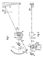
- 1 denotes a parallel beam which is obtained from an expanded laser beam.
- a focusing lens 2 which directs the bundle of rays parallel to and in the vicinity of an axis of rotation 20 of a drive motor with a bearing 19 onto one of two tilt-insensitive prisms 4, 5 cemented next to one another, which are generally referred to as tilt-insensitive reflex bodies .
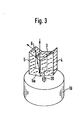
- the structure of the two prisms results in particular from FIG. 3: They can be rotated above the drive motor and bearing 19 about the axis of rotation 20, with which they are connected in a manner not shown. It can be seen from FIG. 3 how the two prisms 4 and 5 are arranged essentially parallel to the axis of rotation 20.
- Each of the two prisms has an upper active reflective surface e.g. 6, which faces an second reflecting surface at an angle of 45 °.
- the second reflective surface e.g. 5a is inclined by about 5 ° to the horizontal.
- the two active upper reflex surfaces of the two prisms are partially covered by a straight third prism 3, which serves as an input surface with a horizontal surface that is oriented normally to the beam 1.
- the beam of rays thus runs through the prism 3, through the active reflecting surface 6 to the reflecting surface 5a, is reflected back by the latter onto the inside of the active reflecting surface 6 and emerges from the prism at a right angle to the incoming beam of rays.
- Each of the two active reflecting surfaces has a rotation angle or output half-angle B.
- the output beam is directed onto a manganese mirror with a negative lens 8 on a concave mirror 9.
- the rotating movement of the active reflecting surfaces is an intermediate image plane of the focusing lens 2 on an arc.
- the focusing line coincides with the focal plane of the manganese level and is labeled 7.
- the beam deflection at the manganese level is designed at 25 °, of which about half. to the concave mirror 9 and half to the negative lens 8.
- the manganese level creates a convergence point or an entrance pupil on a flat front surface 10 of an fe lens arrangement 18.
- the main element with the flat front surface 10 and a beam-concentric convex surface 11 belongs to the fe lens arrangement, which can be of conventional construction V. It consists of refractive glass. A further lens made of highly refractive glass, which has a convex radiation-concentric starting surface 12, is cemented to this lens.
- the fe lens arrangement also includes an uncondensed negative diverging lens 13, which is used to correct a distortion over-correction on the plane surface 10.
- the correction of the overall system can be moved entirely into the fe lens arrangement or the telescope system.
- the telescope system includes the focusing lens 2, the active reflective surface screwed in, and the manganese mirror.
- the f ⁇ lens arrangement is finally completed by a field-flattening concave mirror 14 which is connected between a flat image plane 15 and the lenses with the surfaces 10, 11, 12.
- the field-flattening mirror 14 shortens the beam path between the lenses mentioned and the flat image plane.
- FIGS. 1 and 2 it is indicated at 17 that a parallel beam of rays emerges from the manganese mirror in the direction of the fe lens arrangement.
- the reference number 16 indicates the position of additional or alternative correction elements, which in simpler optical systems, i.e. in another embodiment, may be desired. A lot of space is advantageously available for such correction elements 16, since the pupil is located at a large distance from the axis of rotation 20 in the area of the plane surface 10.
- a plano-concave lens can be provided as a correction element 16, onto which the parallel beam 17 falls and which specifies such distortion in the imaging lens system 18 that the concave mirror 14 can be omitted and a distortion-free image is nevertheless created in the image plane 15.
- the virtual image generated can be free of astigmatism and coma.
- a so-called modified stone healing periscope can be provided as the imaging lens system 18, which images the virtual image in a concave image shell, which is generated by the plano-concave lens 16, onto the plane image plane 15.
- an astigmatism of the imaging lens system 18 can be corrected in a relatively simple manner by setting a deviation from the parallelism of the parallel beam.
- the field-leveling concave mirror 14 can thus be saved.
- the optical system can be designed without distortion with little effort.
- the invention allows the use of a large effective angle of rotation of the two tilt-resistant reflex bodies. Since only two reflex bodies are necessary, their distance from the axis of rotation can be kept small, which results in further advantages, in particular low centrifugal forces.
Applications Claiming Priority (2)
| Application Number | Priority Date | Filing Date | Title |
|---|---|---|---|
| DE19843434841 DE3434841A1 (de) | 1984-09-22 | 1984-09-22 | Optisches laserstrahl-ablenksystem |
| DE3434841 | 1984-09-22 |
Publications (1)
| Publication Number | Publication Date |
|---|---|
| EP0179213A1 true EP0179213A1 (fr) | 1986-04-30 |
Family
ID=6246078
Family Applications (1)
| Application Number | Title | Priority Date | Filing Date |
|---|---|---|---|
| EP85109967A Withdrawn EP0179213A1 (fr) | 1984-09-22 | 1985-08-08 | Dispositif optique de déviation d'un faisceau laser |
Country Status (4)
| Country | Link |
|---|---|
| US (1) | US4690485A (fr) |
| EP (1) | EP0179213A1 (fr) |
| JP (1) | JPS61117516A (fr) |
| DE (1) | DE3434841A1 (fr) |
Cited By (3)
| Publication number | Priority date | Publication date | Assignee | Title |
|---|---|---|---|---|
| WO1988006744A1 (fr) * | 1987-03-05 | 1988-09-07 | Optische Werke G. Rodenstock | Dispositif deflecteur de faisceaux de rayons |
| WO1993006517A1 (fr) * | 1991-09-26 | 1993-04-01 | Linotype-Hell Ag | Dispositif de deflexion de faisceau lumineux |
| DE10261530A1 (de) * | 2002-12-23 | 2004-07-22 | Gerhard Wanger | Optisches Element zur Anbringung an einer Welle |
Families Citing this family (8)
| Publication number | Priority date | Publication date | Assignee | Title |
|---|---|---|---|---|
| DE3854680T2 (de) * | 1987-04-24 | 1996-04-18 | Dainippon Screen Mfg | Optisches System für ein Lichtpunktabtastgerät. |
| US4947039A (en) * | 1988-10-17 | 1990-08-07 | Eotron Corporation | Flat stationary field light beam scanning device |
| JPH0364726A (ja) * | 1989-08-02 | 1991-03-20 | Minolta Camera Co Ltd | 光ビーム走査光学系 |
| US5168386A (en) * | 1990-10-22 | 1992-12-01 | Tencor Instruments | Flat field telecentric scanner |
| DE4219102C2 (de) * | 1992-06-11 | 1994-10-13 | Hell Ag Linotype | Strahlablenker |
| JP3330248B2 (ja) * | 1995-02-20 | 2002-09-30 | 松下電器産業株式会社 | 光走査装置、画像形成装置及び画像読み取り装置 |
| JP3349122B2 (ja) | 1999-09-29 | 2002-11-20 | 松下電器産業株式会社 | 光走査装置 |
| DE102014007338A1 (de) | 2014-05-17 | 2015-11-19 | Daimler Ag | Oszillierende Strahlführung für die Laserbearbeitung |
Citations (7)
| Publication number | Priority date | Publication date | Assignee | Title |
|---|---|---|---|---|
| US3519325A (en) * | 1965-10-08 | 1970-07-07 | United Aircraft Corp | High aperture wide field varifocal scanning system |
| US3667360A (en) * | 1969-04-23 | 1972-06-06 | Columbia Broadcasting Syst Inc | Optical scanning system |
| US3750189A (en) * | 1971-10-18 | 1973-07-31 | Ibm | Light scanning and printing system |
| US3873180A (en) * | 1973-09-10 | 1975-03-25 | Ampex | Light beam scanning system with scan angle demagnification |
| US3966328A (en) * | 1973-10-16 | 1976-06-29 | Aga Aktiebolag | Device for generating a spatial reference plane |
| EP0016630A1 (fr) * | 1979-03-26 | 1980-10-01 | Xerox Corporation | Dispositif de balayage optique |
| US4382680A (en) * | 1979-09-26 | 1983-05-10 | Hamar M R | Apparatus and process for sweeping a flat optical light plane |
Family Cites Families (2)
| Publication number | Priority date | Publication date | Assignee | Title |
|---|---|---|---|---|
| CH558572A (de) * | 1972-08-10 | 1975-01-31 | Zellweger Uster Ag | Optische abtastvorrichtung. |
| US4154507A (en) * | 1977-12-08 | 1979-05-15 | Jersey Nuclear-Avco Isotopes, Inc. | Optical combiner/distributor using V-shaped mirror assembly |
-
1984
- 1984-09-22 DE DE19843434841 patent/DE3434841A1/de not_active Withdrawn
-
1985
- 1985-08-08 EP EP85109967A patent/EP0179213A1/fr not_active Withdrawn
- 1985-09-20 JP JP60206715A patent/JPS61117516A/ja active Pending
- 1985-09-20 US US06/778,585 patent/US4690485A/en not_active Expired - Lifetime
Patent Citations (7)
| Publication number | Priority date | Publication date | Assignee | Title |
|---|---|---|---|---|
| US3519325A (en) * | 1965-10-08 | 1970-07-07 | United Aircraft Corp | High aperture wide field varifocal scanning system |
| US3667360A (en) * | 1969-04-23 | 1972-06-06 | Columbia Broadcasting Syst Inc | Optical scanning system |
| US3750189A (en) * | 1971-10-18 | 1973-07-31 | Ibm | Light scanning and printing system |
| US3873180A (en) * | 1973-09-10 | 1975-03-25 | Ampex | Light beam scanning system with scan angle demagnification |
| US3966328A (en) * | 1973-10-16 | 1976-06-29 | Aga Aktiebolag | Device for generating a spatial reference plane |
| EP0016630A1 (fr) * | 1979-03-26 | 1980-10-01 | Xerox Corporation | Dispositif de balayage optique |
| US4382680A (en) * | 1979-09-26 | 1983-05-10 | Hamar M R | Apparatus and process for sweeping a flat optical light plane |
Non-Patent Citations (1)
| Title |
|---|
| JOURNAL OF ELECTRONIC ENGINEERING, Nr. 135, März 1978, Seiten 31-33, Tokyo, JP; M. SHIRAGAMI: "Laser beam printers print chinese ideographs" * |
Cited By (4)
| Publication number | Priority date | Publication date | Assignee | Title |
|---|---|---|---|---|
| WO1988006744A1 (fr) * | 1987-03-05 | 1988-09-07 | Optische Werke G. Rodenstock | Dispositif deflecteur de faisceaux de rayons |
| WO1993006517A1 (fr) * | 1991-09-26 | 1993-04-01 | Linotype-Hell Ag | Dispositif de deflexion de faisceau lumineux |
| US5426529A (en) * | 1991-09-26 | 1995-06-20 | Linotype-Hell Ag | Light beam deflection means |
| DE10261530A1 (de) * | 2002-12-23 | 2004-07-22 | Gerhard Wanger | Optisches Element zur Anbringung an einer Welle |
Also Published As
| Publication number | Publication date |
|---|---|
| JPS61117516A (ja) | 1986-06-04 |
| DE3434841A1 (de) | 1986-04-03 |
| US4690485A (en) | 1987-09-01 |
Similar Documents
| Publication | Publication Date | Title |
|---|---|---|
| DE4028359C2 (de) | Bildstabilisierungseinrichtung | |
| DE102017200692A1 (de) | Omnidirektionale Beleuchtungsvorrichtung und Verfahren zum Abtasten eines Raumwinkelbereichs | |
| DE2306185A1 (de) | Verfahren und vorrichtung zur kompensation des pyramidenfehlers eines spiegelrades | |
| DE3806169C2 (fr) | ||
| EP0179213A1 (fr) | Dispositif optique de déviation d'un faisceau laser | |
| EP0152882B1 (fr) | Dispositif optique et mécanique de diffraction | |
| DE2601327C2 (de) | Strahlungsabtastsystem | |
| DE3935239A1 (de) | Abtastgeraet | |
| DE3837553A1 (de) | Optisches abtastsystem fuer die verwendung in einem laserstrahldrucker | |
| EP0275532B1 (fr) | Dispositif de balayage optomécanique | |
| EP1245985B1 (fr) | Dispositif d'écriture d'image avec optique de type Offner | |
| DE2227367C3 (de) | Lichtablenkeinrichtung mit zwei drehbaren Spiegeln | |
| DE3307484C2 (de) | Optisch-mechanischer Abtaster | |
| DE3048132A1 (de) | Automatisches linsenmessgeraet | |
| DE60105650T2 (de) | Lichtbrechender optischer reflektor | |
| EP3011393B1 (fr) | Dispositif de balayage | |
| DE60301453T2 (de) | Optische Abtasteinrichtung | |
| DE4441341C2 (de) | Trommelbelichter oder Trommelscanner | |
| DE4219102C2 (de) | Strahlablenker | |
| DE19546977A1 (de) | Abtastobjektiv | |
| DE3047813A1 (de) | Optische lichtfleck-abtastvorrichtung fuer ein photoempfindliches bahnmaterial bei optischen photosetzgeraeten | |
| DE1772827B2 (fr) | ||
| EP0051274A1 (fr) | Dispositif pour le balayage d'un champ d'image | |
| DE3020342A1 (de) | Abtastvorrichtung fuer kartesische waermebilder | |
| EP1088251A1 (fr) | Systeme d'adaptateur optique pour un appareil de prise de vues |
Legal Events
| Date | Code | Title | Description |
|---|---|---|---|
| PUAI | Public reference made under article 153(3) epc to a published international application that has entered the european phase |
Free format text: ORIGINAL CODE: 0009012 |
|
| AK | Designated contracting states |
Kind code of ref document: A1 Designated state(s): AT CH DE GB LI |
|
| 17P | Request for examination filed |
Effective date: 19861025 |
|
| 17Q | First examination report despatched |
Effective date: 19870921 |
|
| STAA | Information on the status of an ep patent application or granted ep patent |
Free format text: STATUS: THE APPLICATION IS DEEMED TO BE WITHDRAWN |
|
| 18D | Application deemed to be withdrawn |
Effective date: 19880202 |
|
| RIN1 | Information on inventor provided before grant (corrected) |
Inventor name: PLAOT, MICHAEL |