EP0179213A1 - Laser beam deflecting optical device - Google Patents
Laser beam deflecting optical device Download PDFInfo
- Publication number
- EP0179213A1 EP0179213A1 EP85109967A EP85109967A EP0179213A1 EP 0179213 A1 EP0179213 A1 EP 0179213A1 EP 85109967 A EP85109967 A EP 85109967A EP 85109967 A EP85109967 A EP 85109967A EP 0179213 A1 EP0179213 A1 EP 0179213A1
- Authority
- EP
- European Patent Office
- Prior art keywords
- laser beam
- lens
- plane
- beam deflection
- optical laser
- Prior art date
- Legal status (The legal status is an assumption and is not a legal conclusion. Google has not performed a legal analysis and makes no representation as to the accuracy of the status listed.)
- Withdrawn
Links
Images
Classifications
-
- B—PERFORMING OPERATIONS; TRANSPORTING
- B41—PRINTING; LINING MACHINES; TYPEWRITERS; STAMPS
- B41B—MACHINES OR ACCESSORIES FOR MAKING, SETTING, OR DISTRIBUTING TYPE; TYPE; PHOTOGRAPHIC OR PHOTOELECTRIC COMPOSING DEVICES
- B41B21/00—Common details of photographic composing machines of the kinds covered in groups B41B17/00 and B41B19/00
- B41B21/16—Optical systems
-
- B—PERFORMING OPERATIONS; TRANSPORTING
- B41—PRINTING; LINING MACHINES; TYPEWRITERS; STAMPS
- B41J—TYPEWRITERS; SELECTIVE PRINTING MECHANISMS, i.e. MECHANISMS PRINTING OTHERWISE THAN FROM A FORME; CORRECTION OF TYPOGRAPHICAL ERRORS
- B41J2/00—Typewriters or selective printing mechanisms characterised by the printing or marking process for which they are designed
- B41J2/435—Typewriters or selective printing mechanisms characterised by the printing or marking process for which they are designed characterised by selective application of radiation to a printing material or impression-transfer material
- B41J2/47—Typewriters or selective printing mechanisms characterised by the printing or marking process for which they are designed characterised by selective application of radiation to a printing material or impression-transfer material using the combination of scanning and modulation of light
- B41J2/471—Typewriters or selective printing mechanisms characterised by the printing or marking process for which they are designed characterised by selective application of radiation to a printing material or impression-transfer material using the combination of scanning and modulation of light using dot sequential main scanning by means of a light deflector, e.g. a rotating polygonal mirror
-
- G—PHYSICS
- G02—OPTICS
- G02B—OPTICAL ELEMENTS, SYSTEMS OR APPARATUS
- G02B13/00—Optical objectives specially designed for the purposes specified below
- G02B13/0005—Optical objectives specially designed for the purposes specified below having F-Theta characteristic
-
- G—PHYSICS
- G02—OPTICS
- G02B—OPTICAL ELEMENTS, SYSTEMS OR APPARATUS
- G02B26/00—Optical devices or arrangements for the control of light using movable or deformable optical elements
- G02B26/08—Optical devices or arrangements for the control of light using movable or deformable optical elements for controlling the direction of light
- G02B26/10—Scanning systems
Definitions
- the invention relates to an optical flatbed deflection system according to the preamble of claim 1.
- optical flatbed deflection systems of this type can be used for various applications as input scanners or output scanners.
- a preferred application of the optical flatbed deflection system is the setting of typographic characters by means of a light beam, in particular a laser light source, modulated with pixels at a pixel frequency.
- optical flatbed deflection systems are intended to move a spatially fixed beam of light in the direction of a deflection line over a plane deflection plane, if possible in such a way that normally every deflection period corresponds to an equally long deflection path increment regardless of the position of the increment in the deflection line.
- optical flatbed deflection system of the type mentioned at the outset which includes a rotating or pivoting reflecting surface, this also means that every angle of rotation of this surface corresponds to a proportional distance in the deflection plane.
- Exact positioning of an image point along the lines in the image plane is also desirable in order to be able to determine the image position by means of a relatively simple rotary encoder which is connected to the rotating active reflection surfaces. Otherwise, a complex measurement with a ruler in the image plane and with a measuring beam deflected analogously to the modulated beam with associated optics is required, which images a moving pixel of the measuring beam on a photo receiver.
- the deflection angle to the vertical is limited on the film plane, since the image point must not be displayed too large, because it is on the edges the image becomes increasingly elliptical.
- the optics arranged between the rotatable or pivotable reflecting surface and the deflecting plane for deflecting a light beam in deflecting positions of the deflecting plane essentially consists of flat field lenses in a multi-unitary and divided manner in relation to a deflecting angle of the rotatable or pivotable reflecting surface correspondingly complex arrangement.
- These lenses are also known as the fe lens.
- a disadvantage of such fe lenses is that they can only be used in a limited range of the deflection angle, especially in the case of high resolution requirements, as in a typographic setting device.
- the entrance angle of such lens systems is also very limited.
- the lens system have an aplanatic single lens with a first, approximately planar surface facing the rotating active reflection surface and with a second, spherical-convex surface facing the deflection plane (image plane) that the main rays hit them essentially radially at all deflection angles and include a field-leveling mirror near the deflection plane (patent application P 34 04 407.8).
- the present invention has for its object to further increase the usable Rotationsr angle of the active reflective surface per line length, in order to keep in particular the distorting influence of the line wobble for a given line length in the deflection plane or in the image plane low.
- the usable rotation angle of an active reflection surface or the exit angle of this reflection surface which is equal to the entrance angle of the telescope-like system, becomes so large that a rotation angle of 130 ° per line can be used without complex changes to the imaging lens system. This immediately results in a significant reduction in the line wobble in the deflection plane, since this is reciprocal to the usable rotation angle of the active reflecting surface.
- the large usable angle of rotation creates a requirement for the telescope-like system to provide only two rotating reflective bodies instead of a polygonal polygon, each of which is designed to be tilt-insensitive according to the pentaprism principle.
- These reflective bodies constructed according to the pentaprism principle each have a reflective surface, via which an incident beam of rays is reflected back to an active reflective surface, which is inclined at 45 ° to the first-mentioned reflective surface and pivots the beam of rays over the imaging optical lens system. So that is
- the exit angle at which the beam emerges from the active reflecting surface is practically independent of the angle of entry of the beam into the tilt-prism. There is always a beam deflection of 90 ° between the input beam and the output beam of the active reflection surface. A line wobble is practically eliminated via the rotation angle of this active reflecting surface.
- each active rotating reflex body allows the use of a relatively low-cost position sensor with high resolution, which is coupled to the axis of rotation of the reflective surfaces.
- the telescope-like optical system according to claim 3 is particularly advantageously produced with a concave mirror, the focusing plane of which coincides with the intermediate image plane of the active reflecting surface reflecting the beam in each case and an upstream focusing lens.
- the intermediate image plane of the focusing lens also lies on a circular arc due to the rotational movement of the active reflecting surface.
- a manganese mirror is advantageously used as a concave mirror.
- the beam deflection at the manganese mirror is designed so that approximately half of it is due to the concave mirror itself and the remaining half to the associated lens.
- the imaging lens system according to claim 6 can consist of an fe lens arrangement and a field-flattening concave mirror. A small distance between the fe lens arrangement and the concave mirror can be maintained with a large deflection angle.
- the fe lens arrangement is particularly expediently constructed according to claim 7.
- the fe lens arrangement and in particular the front plane surface can be kept small, since the flat bed deflection system according to the invention forms an entrance pupil in the front plane surface.
- the fe lens arrangement can be supplemented by a non-cemented, downstream negative diverging lens for a further correction, in particular in the case of a distortion over-correction on the plane surface 10.
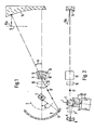
- 1 denotes a parallel beam which is obtained from an expanded laser beam.
- a focusing lens 2 which directs the bundle of rays parallel to and in the vicinity of an axis of rotation 20 of a drive motor with a bearing 19 onto one of two tilt-insensitive prisms 4, 5 cemented next to one another, which are generally referred to as tilt-insensitive reflex bodies .
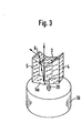
- the structure of the two prisms results in particular from FIG. 3: They can be rotated above the drive motor and bearing 19 about the axis of rotation 20, with which they are connected in a manner not shown. It can be seen from FIG. 3 how the two prisms 4 and 5 are arranged essentially parallel to the axis of rotation 20.
- Each of the two prisms has an upper active reflective surface e.g. 6, which faces an second reflecting surface at an angle of 45 °.
- the second reflective surface e.g. 5a is inclined by about 5 ° to the horizontal.
- the two active upper reflex surfaces of the two prisms are partially covered by a straight third prism 3, which serves as an input surface with a horizontal surface that is oriented normally to the beam 1.
- the beam of rays thus runs through the prism 3, through the active reflecting surface 6 to the reflecting surface 5a, is reflected back by the latter onto the inside of the active reflecting surface 6 and emerges from the prism at a right angle to the incoming beam of rays.
- Each of the two active reflecting surfaces has a rotation angle or output half-angle B.
- the output beam is directed onto a manganese mirror with a negative lens 8 on a concave mirror 9.
- the rotating movement of the active reflecting surfaces is an intermediate image plane of the focusing lens 2 on an arc.
- the focusing line coincides with the focal plane of the manganese level and is labeled 7.
- the beam deflection at the manganese level is designed at 25 °, of which about half. to the concave mirror 9 and half to the negative lens 8.
- the manganese level creates a convergence point or an entrance pupil on a flat front surface 10 of an fe lens arrangement 18.
- the main element with the flat front surface 10 and a beam-concentric convex surface 11 belongs to the fe lens arrangement, which can be of conventional construction V. It consists of refractive glass. A further lens made of highly refractive glass, which has a convex radiation-concentric starting surface 12, is cemented to this lens.
- the fe lens arrangement also includes an uncondensed negative diverging lens 13, which is used to correct a distortion over-correction on the plane surface 10.
- the correction of the overall system can be moved entirely into the fe lens arrangement or the telescope system.
- the telescope system includes the focusing lens 2, the active reflective surface screwed in, and the manganese mirror.
- the f ⁇ lens arrangement is finally completed by a field-flattening concave mirror 14 which is connected between a flat image plane 15 and the lenses with the surfaces 10, 11, 12.
- the field-flattening mirror 14 shortens the beam path between the lenses mentioned and the flat image plane.
- FIGS. 1 and 2 it is indicated at 17 that a parallel beam of rays emerges from the manganese mirror in the direction of the fe lens arrangement.
- the reference number 16 indicates the position of additional or alternative correction elements, which in simpler optical systems, i.e. in another embodiment, may be desired. A lot of space is advantageously available for such correction elements 16, since the pupil is located at a large distance from the axis of rotation 20 in the area of the plane surface 10.
- a plano-concave lens can be provided as a correction element 16, onto which the parallel beam 17 falls and which specifies such distortion in the imaging lens system 18 that the concave mirror 14 can be omitted and a distortion-free image is nevertheless created in the image plane 15.
- the virtual image generated can be free of astigmatism and coma.
- a so-called modified stone healing periscope can be provided as the imaging lens system 18, which images the virtual image in a concave image shell, which is generated by the plano-concave lens 16, onto the plane image plane 15.
- an astigmatism of the imaging lens system 18 can be corrected in a relatively simple manner by setting a deviation from the parallelism of the parallel beam.
- the field-leveling concave mirror 14 can thus be saved.
- the optical system can be designed without distortion with little effort.
- the invention allows the use of a large effective angle of rotation of the two tilt-resistant reflex bodies. Since only two reflex bodies are necessary, their distance from the axis of rotation can be kept small, which results in further advantages, in particular low centrifugal forces.
Abstract
Ein optisches Flachbett-Ablenksystem umfaßt mindestens eine rotierende aktive Reflexfläche (6) zum Ablenken eines Strahlenbündels (1) entlang einer Ablenkzeile in einer planen Ablenkebene (15) sowie ein zwischen der aktiven Reflexfläche und der Ablenkebene angeordnetes abbildendes Linsensystem (fϑ-Linsenanordnung 18). Um den störenden Einfluß des Lagerwobbelns auf die Abbildung zu verringern, ist dem abbildenden Linsensystem (18) ein umgekehrt fernrohrartiges optisches System (2 - 8) vorgeschaltet, welches einen Ausgangswinkel (2B) der aktiven Reflexflächen vergrößert. In Verbindung damit sind nur zwei rotierende aktive Reflexflächen vorgesehen, von denen je eine an einem nach dem Pentaprismenprinzip kippunempfindlichen Prisma (z.B. 4) ausgebildet ist.An optical flatbed deflection system comprises at least one rotating active reflection surface (6) for deflecting a beam (1) along a deflection line in a flat deflection plane (15) and an imaging lens system (fϑ lens arrangement 18) arranged between the active reflection surface and the deflection plane. In order to reduce the disturbing influence of the bearing wobble on the image, the imaging lens system (18) is preceded by an inverted telescope-like optical system (2-8), which enlarges an output angle (2B) of the active reflective surfaces. In connection with this, only two rotating active reflex surfaces are provided, one of which is formed on a prism (e.g. 4) that is insensitive to tilting according to the pentaprism principle.
Description
Die Erfindung betrifft ein optisches Flachbett-Ablenksystem nach dem Oberbegriff des Anspruchs 1.The invention relates to an optical flatbed deflection system according to the preamble of claim 1.
Derartige bekannte optische Flachbett-Ablenksysteme können für verschiedene Anwendungen als Eingabescanner oder Ausgabescanner verwendet werden.Known optical flatbed deflection systems of this type can be used for various applications as input scanners or output scanners.
Im vorliegenden Fall ist eine bevorzugte Anwendung des optischen Flachbett-Ablenksystems das Setzen typographischer Schriftzeichen mittels eines entsprechend Bildpunkten mit einer Pixelfrequenz modulierten Lichtstrahlenbündels, insbesondere einer Laserlichtquelle.In the present case, a preferred application of the optical flatbed deflection system is the setting of typographic characters by means of a light beam, in particular a laser light source, modulated with pixels at a pixel frequency.
Generell sollen solche optischen Flachbett-Ablenksysteme ein räumlich feststehendes Lichtstrahlenbündel in Richtung einer Ablenkzeile über eine plane Ablenkebene bewegen, und zwar möglichst so, daß normalerweise jeder Pixelperiode ein gleich langes Ablenkweginkrement unabhängig von der Lage des Inkrements in der Ablenkzeile entspricht. Dies beinhaltet auch bei dem optischen Flachbett-Ablenksystem der eingangs genannten Gattung mit einer dreh- oder schwenkbaren spiegelnden Fläche, daß jedem Drehwinkel dieser Fläche eine proportionale Strecke in der Ablenkebene korrespondiert. Außerdem sollen zwischen aufeinanderfolgenden Ablenkzeilen konstante Abstände vorliegen. Diese Beziehung ist wegen einer Reihe von Fehlermöglichkeiten, die u.a. auf die begrenzte Fertigungsgenauigkeit solcher Flachbett-Ablenksysteme zurückgehen, begrenzt: Insbesondere können das sogenannte Lagerwobbeln des Lagers, in dem die dreh- oder schwenkbare spiegelnde Fläche gelagert ist, und der sogenannte Polygonpyramidalfehler im Falle eines Polygons aus mehreren gegeneinander versetzten reflektierenden Flächen die Beziehung aufeinanderfolgender Ablenkzeilen stören (der Polygonpyramidalfehler beinhaltet die Winkelabweichung je einer reflektierenden Fläche des Polygons gegenüber einer Bezugsfläche).In general, such optical flatbed deflection systems are intended to move a spatially fixed beam of light in the direction of a deflection line over a plane deflection plane, if possible in such a way that normally every deflection period corresponds to an equally long deflection path increment regardless of the position of the increment in the deflection line. In the case of the optical flatbed deflection system of the type mentioned at the outset, which includes a rotating or pivoting reflecting surface, this also means that every angle of rotation of this surface corresponds to a proportional distance in the deflection plane. In addition, there should be constant distances between successive deflection lines. This relationship is limited due to a number of error possibilities, which can be traced back to the limited manufacturing accuracy of such flatbed deflection systems: In particular, the so-called bearing wobble of the bearing in which the rotating or swiveling reflecting surface is mounted, and the so-called polygon pyramidal error in the case of a Polygons from several against mutually reflecting surfaces disrupt the relationship of successive deflection lines (the polygon pyramidal error includes the angular deviation of one reflecting surface of the polygon from a reference surface).
Um trotz solcher störender Einflüsse Ablenkzeilen in einer planen Ablenkebene exakt abzulenken, was insbesondere bei typographischen Anwendungen besonders wünschenswert ist, da hier bereits kleinste Unregelmäßigkeiten störend auffallen, ist es naheliegend, einen möglichst großen Ablenkwinkel anzustreben. Bei gegebener Ablenklänge kann nämlich durch einen größeren Ablenkwinkel der optisch wirksame Abstand oder Arm zwischen der dreh- oder schwenkbaren spiegelnden Fläche und der Ablenkebene entsprechend reduziert werden. Dadurch wirken sich Ungenauigkeiten der Bewegung und Stellung der spiegelnden Fläche, beispielsweise eines Polygons, weniger in der Ablenkebene aus.In order to precisely deflect deflection lines in a plane deflection plane despite such disturbing influences, which is particularly desirable in typographic applications, since even the smallest irregularities are disturbing, it is obvious to aim for the largest possible deflection angle. For a given deflection length, the optically effective distance or arm between the rotatable or pivotable reflecting surface and the deflection plane can be reduced accordingly by a larger deflection angle. As a result, inaccuracies in the movement and position of the reflecting surface, for example of a polygon, have less effect in the deflection plane.
Eine exakte Positionierung eines Bildpunktes längs der Zeilen in der Bildebene ist auch deswegen wünschenswert, um die Bildposition durch einen relativ einfachen Drehmeßgeber bestimmen zu können, der mit den rotierenden aktiven Reflexflächen in Verbindung steht. Anderenfalls ist eine aufwendige Messung mit einem Rasterlineal in der Bildebene sowie mit einem analog zu dem modulierten Strahlenbündel abgelenkten Meßstrahlenbündel mit zugehöriger Optik erforderlich, die einen bewegten Bildpunkt des Meßstrahlenbündels auf einem Fotoempfänger abbildet.Exact positioning of an image point along the lines in the image plane is also desirable in order to be able to determine the image position by means of a relatively simple rotary encoder which is connected to the rotating active reflection surfaces. Otherwise, a complex measurement with a ruler in the image plane and with a measuring beam deflected analogously to the modulated beam with associated optics is required, which images a moving pixel of the measuring beam on a photo receiver.
In Flachbett-Ablenksystemen ist der Ablenkwinkel zur Senkrechten auf der Filmebene begrenzt, da der Bildpunkt nicht zu groß abgebildet werden darf, denn an den Rändern wird die Abbildung immer stärker ellipsenförmig. - In typischen bekannten optischen Flachbett-Ablenksystemen besteht die zwischen der dreh- oder schwenkbaren spiegelnden Fläche und der Ablenkebene angeordnete Optik zum Ablenken eines Lichtstrahlenbündels in Ablenkpositionen der Ablenkebene im wesentliche proportional zu einem Ablenkwinkel der dreh-oder schwenkbaren spiegelnden Fläche aus Flachfeldlinsen in einer vielgliedrigen und entsprechend aufwendigen Anordnung. Diese Linsen werden auch als fe-Linse bezeichnet. Nachteilig ist aber bei solchen fe-Linsen, daß sie nur in einem begrenzten Bereich des Ablenkwinkels vor allem bei hohen Ansprüchen an die Auflösung wie in einem typographischen Setzgerät verwendet werden können. Der Eingangswinkel solcher Linsensysteme ist ebenfalls stark begrenzt.In flatbed deflection systems, the deflection angle to the vertical is limited on the film plane, since the image point must not be displayed too large, because it is on the edges the image becomes increasingly elliptical. In typical known optical flatbed deflection systems, the optics arranged between the rotatable or pivotable reflecting surface and the deflecting plane for deflecting a light beam in deflecting positions of the deflecting plane essentially consists of flat field lenses in a multi-unitary and divided manner in relation to a deflecting angle of the rotatable or pivotable reflecting surface correspondingly complex arrangement. These lenses are also known as the fe lens. A disadvantage of such fe lenses, however, is that they can only be used in a limited range of the deflection angle, especially in the case of high resolution requirements, as in a typographic setting device. The entrance angle of such lens systems is also very limited.
Um den Eingangswinkel solcher linearisierenden Linsensysteme zu vergrößern, ist bereits vorgeschlagen worden, daß das Linsensystem eine aplanatische Einzellinse mit einer ersten, der rotierenden aktiven Reflexfläche zugewandten, annähernd planen Fläche und mit einer zweiten, der Ablenkebene (Bildebene) zugewandten, dergestalt sphärisch-konvexen Fläche, daß die Hauptstrahlen bei allen Ablenkwinkeln im wesentlichen radial auf sie treffen, sowie einen feldebnenden Spiegel in der Nähe der Ablenkebene umfaßt (Patentanmeldung P 34 04 407.8).In order to increase the entrance angle of such linearizing lens systems, it has already been proposed that the lens system have an aplanatic single lens with a first, approximately planar surface facing the rotating active reflection surface and with a second, spherical-convex surface facing the deflection plane (image plane) that the main rays hit them essentially radially at all deflection angles and include a field-leveling mirror near the deflection plane (patent application P 34 04 407.8).
Der vorliegenden Erfindung liegt die Aufgabe zugrunde, nach einem anderen Prinzip den pro Zeilenlänge nutzbaren Rotationsr winkel der aktiven Reflexfläche weiter zu vergrößern, um damit insbesondere den verzerrenden Einfluß des Zeilentaumels bei gegebener Zeilenlänge in der Ablenkebene bzw. in der Bildebene gering zu halten.The present invention has for its object to further increase the usable Rotationsr angle of the active reflective surface per line length, in order to keep in particular the distorting influence of the line wobble for a given line length in the deflection plane or in the image plane low.
Diese Aufgabe wird durch die im kennzeichnenden Teil des Anspruchs 1 angegebene Erfindung gelöst.This object is achieved by the invention specified in the characterizing part of claim 1.
Durch das umgekehrte fernrohrartige optische System wird ohne aufwendige Veränderung des abbildenden Linsensystems der nutzbare Rotationswinkel einer aktiven Reflexfläche bzw. der Ausgangswinkel dieser Reflexfläche, die gleich dem Eingangswinkel des fernrohrartigen Systems ist, so groß, daß ein Rotationswinkel von 130° pro Zeile genutzt werden kann. Daraus ergibt sich unmittelbar eine erhebliche Reduzierung des Zeilentaumels in der Ablenkebene, da dieser reziprok dem nutzbaren Rotationswinkel der aktiven Reflexfläche ist.Through the reverse telescope-like optical system, the usable rotation angle of an active reflection surface or the exit angle of this reflection surface, which is equal to the entrance angle of the telescope-like system, becomes so large that a rotation angle of 130 ° per line can be used without complex changes to the imaging lens system. This immediately results in a significant reduction in the line wobble in the deflection plane, since this is reciprocal to the usable rotation angle of the active reflecting surface.
In besonders günstiger Weise wird durch den großen nutzbaren Rotationswinkel eine Voraussetzung dafür geschaffen, daß mit dem fernrohrartigen System statt eines Vielflächenpolygons nur zwei rotierende Reflexfkörper vorzusehen sind, die jeweils nach dem Pentaprismenprinzip kippunempfindlich ausgebildet sind. Diese nach dem Pentaprismenprinzip aufgebauten Reflexkörper weisen je eine Reflexfläche auf, über die ein auftreffendes Strahlenbündel zu einer aktiven Reflexfläche zurückreflektiert wird, die zu der erstgenannten Reflexfläche um 45° geneigt ist und das Strahlenbündel über das abbildende optische Linsensystem schwenkt. Damit istIn a particularly favorable manner, the large usable angle of rotation creates a requirement for the telescope-like system to provide only two rotating reflective bodies instead of a polygonal polygon, each of which is designed to be tilt-insensitive according to the pentaprism principle. These reflective bodies constructed according to the pentaprism principle each have a reflective surface, via which an incident beam of rays is reflected back to an active reflective surface, which is inclined at 45 ° to the first-mentioned reflective surface and pivots the beam of rays over the imaging optical lens system. So that is
der Ausgangswinkel, unter dem das Strahlenbündel von der aktiven Reflexfläche austritt, praktisch unabhängig von dem Eintrittswinkel des Strahlenbündels in das kippunempfindliche Prisma. Es tritt stets eine Strahlablenkung von 90° zwischen dem Eingangsstrahlenbündel und dem Ausgangsstrahlenbündel der aktiven Reflexfläche ein. Ein Zeilentaumel ist über den Rotationswinkel dieser aktiven Reflexfläche praktisch beseitigt. Darüber hinaus kann durch paarweise Herstellung der beiden kippunempfindlichen Reflexkörper, die in das Ablenksystem eingebaut werden, insbesondere durch gemeinsames Polieren auch bei sonst groben Toleranzen einthe exit angle at which the beam emerges from the active reflecting surface is practically independent of the angle of entry of the beam into the tilt-prism. There is always a beam deflection of 90 ° between the input beam and the output beam of the active reflection surface. A line wobble is practically eliminated via the rotation angle of this active reflecting surface. In addition, by producing the two tilt-insensitive reflex bodies that are installed in the deflection system in pairs, in particular by polishing together, even with otherwise rough tolerances
gleicher Ablenkwinkel für beide aktive Reflexflächen erreicht werden. Da pro Umdrehung der beiden rotierenden aktiven Reflexflächen nur zwei Ablenkzeilen abgetastet werden, kann die Drehzahl wesentlich erhöht werden, woraus sich wiederum ein besserer Gleichlauf ergibt. - Der große Rotationswinkel jeder aktiven rotierenden Reflexkörper ermöglicht die Verwendung eines verhältnismäßig wenig aufwendigen Positionsgebers mit hoher Auflösung, der mit der Drehachse der Reflexflächen gekuppelt ist.the same deflection angle can be achieved for both active reflex surfaces. Since only two deflection lines are scanned per revolution of the two rotating active reflection surfaces, the speed can be increased significantly, which in turn results in better synchronization. - The large angle of rotation of each active rotating reflex body allows the use of a relatively low-cost position sensor with high resolution, which is coupled to the axis of rotation of the reflective surfaces.
Es ist bei dem erfindungsgemäßen Flachbett-Ablenksystem nicht unbedingt erforderlich, daß ein fe-Linsensystem als abbildendes Linsensystem verwendet wird, vielmehr genügt hierzu eine einfache Optik.In the flatbed deflection system according to the invention, it is not absolutely necessary for an fe lens system to be used as an imaging lens system; rather, simple optics are sufficient for this.
Besonders vorteilhaft wird zur Ausbildung eines kompakten Flachbett-Ablenksystems das fernrohrartige optische System nach Anspruch 3 mit einem Hohlspiegel erzeugt, dessen Fokusierebene mit der Zwischenbildebene der jeweils das Strahlenbündel reflektierenden aktiven Reflexfläche und einer vorgeschalteten Fokusierlinse zusammenfällt. Die Zwischenbildebene der Fokusierlinse liegt durch die Rotationsbewegung der aktiven Reflexfläche ebenfalls auf einem Kreisbogen.To form a compact flatbed deflection system, the telescope-like optical system according to
Eine besonders vorteilhafte Anordnung der beiden in dem Flachbett-Ablenksystem vorgesehenen kippunempfindlichen Prismen geht alls Anspruch 4 hervor. - Die beiden kippunempfindlichen Reflexkörper bilden zusammen mit dem sie teilweise überdeckenden geraden Prisma eine verhältnismäßig wenig aufwendig zu fertigende kompakte Einheit.A particularly advantageous arrangement of the two tilt-insensitive prisms provided in the flatbed deflection system is evident from claim 4. The two tilt-insensitive reflex bodies, together with the straight prism partially covering them, form a compact unit which is relatively inexpensive to manufacture.
Vorteilhaft wird ein Manginspiegel als Hohlspiegel verwendet. Die Strahlablenkung am Manginspiegel ist so ausgelegt, daß sie etwa zur Hälfte auf den Hohlspiegel selbst und zur restlichen Hälfte auf die zugehörige Linse entfällt. Mit dem Manginspiegel kann die Korrektur des optischen Systems vereinfacht werden.-Zweckmäßigerweise kann das abbildende Linsensystem nach Anspruch 6 aus einer fe-Linsenanordnung und einem feldebnenden Hohlspiegel bestehen. Dabei kann ein kleiner Abstand zwischen der fe-Linsenanordnung und dem Hohlspiegel bei einem großen Ablenkwinkel eingehalten werden.A manganese mirror is advantageously used as a concave mirror. The beam deflection at the manganese mirror is designed so that approximately half of it is due to the concave mirror itself and the remaining half to the associated lens. With the manganese mirror, the correction of the optical system can be simplified. Expediently, the imaging lens system according to claim 6 can consist of an fe lens arrangement and a field-flattening concave mirror. A small distance between the fe lens arrangement and the concave mirror can be maintained with a large deflection angle.
Die fe-Linsenanordnung ist besonders zweckmäßig nach Anspruch 7 aufgebaut. Die fe-Linsenanordnung und insbesondere die vordere Planfläche können klein gehalten werden, da das erfindungsgemäße Flachbett-Äblenksystem eine Eintrittspupille in der vorderen Planfläche bildet.The fe lens arrangement is particularly expediently constructed according to claim 7. The fe lens arrangement and in particular the front plane surface can be kept small, since the flat bed deflection system according to the invention forms an entrance pupil in the front plane surface.
Die fe-Linsenanordnung kann durch eine unverkittete nachgeschaltete negative Zerstreuungslinse zu einer weiteren Korrektur, insbesondere bei einer Verzeichnungsüberkorrektur an der Planfläche 10 ergänzt werden.The fe lens arrangement can be supplemented by a non-cemented, downstream negative diverging lens for a further correction, in particular in the case of a distortion over-correction on the plane surface 10.
Die Erfindung wird im folgenden anhand einer Zeichnung mit drei Figuren erläutert. Es zeigen:
- Fig. 1 ein Ausführungsbeispiel des Flachbett-Ablenksystems schematisch in einer Ansicht von unten auf das Flachbett-Ablenksystem ohne Antriebsmotor;
- Fig. 2 eine Seitenansicht des Flachbett-Ablenksystems nach Fig. 1; und
- Fig. 3 eine Einzelheit des Flachbett-Ablenksystems nach den Figuren 1 und 2, insbesondere die kippunempfindlichen beiden Prismen.
- Figure 1 shows an embodiment of the flatbed deflection system schematically in a view from below of the flatbed deflection system without a drive motor.
- FIG. 2 shows a side view of the flatbed deflection system according to FIG. 1; and
- Fig. 3 shows a detail of the flatbed deflection system according to Figures 1 and 2, in particular the tilt-insensitive two prisms.
Zunächst beginnend mit Figur 2 ist mit 1 ein paralleles Strahlenbündel bezeichnet, welches aus einem aufgeweiteten Laserstrahl gewonnen ist. Im Strahlengang dieses Strahlenbündels befindet sich eine Fokusierlinse 2, die das Strahlenbündel parallel zu und in der Nähe von einer Drehachse 20 eines Antriebsmotors mit einem Lager 19 auf jeweils eines von zwei nebeneinander verkitteten kippunempfindlichen Prismen 4, 5 richtet, die generell als kippunempfindliche Reflexkörper bezeichnet werden.First, starting with FIG. 2, 1 denotes a parallel beam which is obtained from an expanded laser beam. In the beam path of this bundle of rays there is a focusing lens 2 which directs the bundle of rays parallel to and in the vicinity of an axis of
Der Aufbau der beiden Prismen ergibt sich insbesondere aus Fig. 3: Sie sind oberhalb des Antriebsmotors und Lagers 19 um die Rotationsachse 20, mit der sie in nicht dargestellter Weise in Verbindung stehen, drehbar. Es ist aus Fig. 3 ersichtlich, wie die beiden Prismen 4 und 5 im wesentlichen parallel zur Rotationsachse 20 angeordnet sind. Jedes der beiden Prismen weist eine obere aktive Reflexfläche z.B. 6 auf, die in einem Winkel von 45° einer zweiten Reflexfläche gegenübersteht. Die zweite Reflexfläche z.B.5a ist gegenüber der Horizontalen um etwa 5° geneigt. Die beiden aktiven oberen Reflexflächen der beiden Prismen sind teilweise durch ein gerades drittes Prisma 3 überdeckt, welches mit einer horizontalen Fläche, die normal zu dem Strahlenbündel 1 orientiert ist, als Eingangsfläche dient. Das Strahlenbündel verläuft also durch das Prisma 3, durch die aktive Reflexfläche 6 zur Reflexflache 5a, wird von dieser zurückreflektiert auf das Innere der aktiven Reflexfläche 6 und tritt von dieser rechtwinklig zu dem eintretenden Strahlenbündel aus dem Prisma aus.The structure of the two prisms results in particular from FIG. 3: They can be rotated above the drive motor and bearing 19 about the axis of
Jede der beiden aktiven Reflexflächen hat einen Rotationswinkel bzw. Ausgangshalbwinkel B. Das Ausgangsstrahlenbündel ist auf einen Manginspiegel mit einer Negativlinse 8 auf einem Hohlspiegel 9 gerichtet. Durch die Drehbewegung der aktiven Reflexflächen liegt eine Zwischenbildebene der Fokusierlinse 2 auf einem Bogen. Die Fokusierlinie fällt mit der Fokusebene des Manginspiegels zusammen und ist mit 7 bezeichnet. Im vorliegenden Fall ist die Strahlablenkung am Manginspiegel auf 25° ausgelegt, wovon etwa die Hälfte . auf den Hohlspiegel 9 und die Hälfte auf die Negativlinse 8 entfällt.Each of the two active reflecting surfaces has a rotation angle or output half-angle B. The output beam is directed onto a manganese mirror with a negative lens 8 on a concave mirror 9. By the rotating movement of the active reflecting surfaces is an intermediate image plane of the focusing lens 2 on an arc. The focusing line coincides with the focal plane of the manganese level and is labeled 7. In the present case, the beam deflection at the manganese level is designed at 25 °, of which about half. to the concave mirror 9 and half to the negative lens 8.
Der Manginspiegel erzeugt einen Konvergenzpunkt bzw. eine Eintrittspupille an einer planen Frontfläche 10 einer fe-Linsenanordnung 18.The manganese level creates a convergence point or an entrance pupil on a flat front surface 10 of an
ausgebildet Zu der fe-Linsenanordnung, die in herkömmlicher Bauweise V sein kann, gehört ein Hauptglied mit der planen Frontfläche 10 und einer strahlkonzentrischen Konvexfläche 11. Sie besteht aus niederbrechendem Glas. Verkittet mit dieser Linse ist eine weitere Linse aus hochbrechendem Glas, die eine konvexe strahlkonzentrische Ausgangsfläche 12 aufweist. Außerdem gehört zu der fe-Linsenanordnung eine unverkittete negative Zerstreuungslinse 13, die zur Korrektur einer Verzeichnungsüberkorrektur an der Planfläche 10 dient.The main element with the flat front surface 10 and a beam-concentric
Die Korrektur des Gesamtsystems kann ganz in die fe-Linsenanordnung verlegt werden oder aber das Fernrohrsystem. Zu dem Fernrohrsystem gehören die Fokusierlinse 2, die jeweils eingedrehte aktive Reflexfläche sowie der Manginspiegel.The correction of the overall system can be moved entirely into the fe lens arrangement or the telescope system. The telescope system includes the focusing lens 2, the active reflective surface screwed in, and the manganese mirror.
Die fθ-Linsenanordnung wird schließlich vervollständigt durch einen zwischen einer planen Bildebene 15 und den Linsen mit den Flächen 10, 11, 12 eingeschalteten feldebnenden Hohlspiegel 14. Der feldebnende Spiegel 14 verkürzt den Strahlengang zwischen den genannten Linsen und der planen Bildebene. Für jede nutzbare Position einer der aktiven Reflexflächen mit jeweils einem Rotationswinkel von beispielsweise 130° pro Zeile wird ein Bildpunkt 15a praktisch verzerrungsfrei in der Bildebene 15 abgebildet, und zwar in einer Zeilenposition, die proportional dem Rotationswinkel ist.The fθ lens arrangement is finally completed by a field-flattening
In den Figuren 1 und 2 ist bei 17 angedeutet, daß aus dem Manginspiegel ein paralleles Strahlenbündel in Richtung der fe-Linsenanordnung austritt. Mit dem Bezugszeichen 16 ist die Position zusätzlicher oder alternativer Korrekturglieder angedeutet, die in einfacheren optischen Systemen, d.h. bei einer anderen Ausführungsform, gewünscht sein können. In vorteilhafter Weise steht viel Raum für solche Korrekturglieder 16 zur Verfügung, da sich die Pupille im Bereich der Planfläche 10 in großem Abstand zu der Drehachse 20 befindet.In FIGS. 1 and 2 it is indicated at 17 that a parallel beam of rays emerges from the manganese mirror in the direction of the fe lens arrangement. The
Im einzelnen kann als Korrekturglied 16 eine Plankonkavlinse vorgesehen sein, auf die das parallele Strahlenbündel 17 fällt und die eine solche Verzeichnung in das abbildende Linsensystem 18 vorgibt, daß der Hohlspiegel 14 entfallen kann und gleichwohl ein verzeichnungsfreies Bild in der Bildebene 15 entsteht.In detail, a plano-concave lens can be provided as a
Indem eine Konkavseite der Plankonkavlinse 16 konzentrisch zu einem Kreuzungspunkt des parallelen Strahlenbündels 17 ausgebildet ist, kann das erzeugte virtuelle Bild frei von Astigmatismus und Koma sein.By forming a concave side of the plano-
In einer vorteilhaften Variante kann als abbildendes Linsensystem 18 ein sogenanntes abgewandeltes Steinheil-Periskop vorgesehen sein, welches das virtuelle Bild in einer konkaven Bildschale, welches von der Plankonkavlinse 16 erzeugt wird, auf die plane Bildebene 15 abbildet. Schließlich kann ein Astigmatismus des abbildenden Linsensystems 18 in wenig aufwendiger Weise dadurch korrigiert werden, daß eine Abweichung von der Parallelität des parallelen Strahlenbündels eingestellt wird.In an advantageous variant, a so-called modified stone healing periscope can be provided as the
Mit den Weiterbildungen gemäß den Ansprüchen 9 bis 12 kann also der feldebnende Hohlspiegel 14 eingespart werden. Das Optische System kann insgesamt mit geringem Aufwand verzeichnungsfrei gestaltet werden.With the developments according to claims 9 to 12, the field-leveling
Generell gestattet die Erfindung die Ausnutzung eines großen effektiven Drehwinkels der beiden kippunempfindlichen Reflexkörper. Da nur zwei Reflexkörper notwendig sind, kann ihr Abstand zu der Rotationsachse gering gehalten werden, woraus sich weitere Vorteile ergeben, insbesondere geringe Zentrifugalkräfte.In general, the invention allows the use of a large effective angle of rotation of the two tilt-resistant reflex bodies. Since only two reflex bodies are necessary, their distance from the axis of rotation can be kept small, which results in further advantages, in particular low centrifugal forces.
Claims (12)
dadurch gekennzeichnet ,
daß die beiden kippunempfindlichen Reflexkörper (4, 5) nebeneinander und im wesentlichen parallel zur Rotationsachse (20) angeordnet sind, daß ein die beiden aktiven Reflexflächen der Prismen außen teilweise überdeckendes, gerades Prisma (3) auf einer normal zur Rotationsachse orientierten Fläche von dem im wesentlichen parallel zur Rotationsachse gerichteten Laserstrahl getroffen wird.4. Optical laser beam deflection system according to one of claims 1 to 3,
characterized ,
that the two tilt-insensitive reflex bodies (4, 5) are arranged next to one another and essentially parallel to the axis of rotation (20), that a partially covering the two active reflecting surfaces of the prisms on the outside, straight prism (3) is hit on a surface oriented normal to the axis of rotation by the laser beam directed essentially parallel to the axis of rotation.
dadurch gekennzeichnet,
daß das abbildende Linsensystem aus einer fe-Linsenanordnung (18) und einem zwischen dieser und der planen Bildebene (15) angeordneten feldebnenden Hohlspiegel (14) besteht.6. Optical laser beam deflection system with a lens system imaging in a plane image plane, according to one of claims 1-5,
characterized,
that the imaging lens system consists of an fe lens arrangement (18) and a field-leveling concave mirror (14) arranged between it and the plane image plane (15).
dadurch gekennzeichnet,
daß die fe-Linsenanordnung (18) ein Hauptglied (10 - 12) mit einer Linse aus einem niederbrechenden Glas mit einer vorderen Planfläche (10) und einer strahlkonzentrischen Konvexfläche (11) sowie mit einer verkitteten Linse aus hochbrechendem Glas mit einer strahlkonzentrischen Außenfläche (12) aufweist,7. Optical laser beam deflection system according to claim 6,
characterized,
that the fe lens arrangement (18) has a main member (10 - 12) with a lens made of low-refractive glass with a front plane surface (10) and a beam-concentric convex surface (11) and with a cemented lens made of highly refractive glass with a beam-concentrating outer surface (12 ) having,
dadurch gekennzeichnet,
daß jeder kippunempfindliche Reflexkörper (4, 5) nach dem Pentaprismenprinzip außer der Reflexfläche (5) eine im Winkel von 45° gegenüberstehende weitere Reflexfläche (6) aufweist.8. Optical laser beam deflection system according to one of claims 1-7,
characterized,
that each tilt-insensitive reflex body (4, 5) according to the pentaprism principle, apart from the reflecting surface (5), has an additional reflecting surface (6) at an angle of 45 °.
dadurch gekennzeichnet,
daß ein von dem Hohlspiegel (9) bzw. Manginspiegel (8, 9) ausgehendes paralleles Strahlenbündel (17) auf eine Plankonkavlinse (16) fällt, deren Planfläche eine solche Verzeichnung in das abbildende Linsensystem (fθ-Linsenanordnung 18) vorgibt, daß bei fehlendem Hohlspiegel 14 ein verzeichnungsfreies Bild in der Bildebene (15) entsteht.9. Optical laser beam deflection system according to one of claims 3 - 8,
characterized,
that a parallel beam (17) coming from the concave mirror (9) or manganese mirror (8, 9) falls on a plano-concave lens (16), the plane of which specifies such a distortion in the imaging lens system (fθ lens arrangement 18) that when missing Concave mirror 14 creates a distortion-free image in the image plane (15).
dadurch gekennzeichnet,
daß eine Konkavseite der Plankonkavlinse (16) konzentrisch zu einem Kruzungspunkt des parallelen Strahlenbündels (17) ist.10. Optical laser beam deflection system according to claim 8,
characterized,
that a concave side of the plano-concave lens (16) is concentric with a point of intersection of the parallel beam (17).
dadurch gekennzeichnet,
daß zur Abbildung eines von der Plankonkavlinse (16)in einer konkaven Bildschale erzeugten virtuellen Bildes auf eine plane Bildebene (15) als abbildendes Linsensystem 18 ein abgewandeltes Steinheil-Periskop vorgesehen ist.11. Optical laser beam deflection system according to claim 9,
characterized,
that a modified Steinheil periscope is provided as an imaging lens system 18 for imaging a virtual image generated by the plano-concave lens (16) in a concave image shell on a flat image plane (15).
dadurch gekennzeichnet,
daß zur Korrektur des Astigmatismus des abbildenden Linsensystems (18) Mittel zur Erzielung einer Abweichung von der Parallelität des parallelen Strahlenbündels (17) vorgesehen sind.12. Optical laser beam deflection system according to one of the preceding claims,
characterized,
that means for correcting the astigmatism of the imaging lens system (18) are provided to achieve a deviation from the parallelism of the parallel beam (17).
Applications Claiming Priority (2)
| Application Number | Priority Date | Filing Date | Title |
|---|---|---|---|
| DE19843434841 DE3434841A1 (en) | 1984-09-22 | 1984-09-22 | OPTICAL LASER BEAM DEFLECTION SYSTEM |
| DE3434841 | 1984-09-22 |
Publications (1)
| Publication Number | Publication Date |
|---|---|
| EP0179213A1 true EP0179213A1 (en) | 1986-04-30 |
Family
ID=6246078
Family Applications (1)
| Application Number | Title | Priority Date | Filing Date |
|---|---|---|---|
| EP85109967A Withdrawn EP0179213A1 (en) | 1984-09-22 | 1985-08-08 | Laser beam deflecting optical device |
Country Status (4)
| Country | Link |
|---|---|
| US (1) | US4690485A (en) |
| EP (1) | EP0179213A1 (en) |
| JP (1) | JPS61117516A (en) |
| DE (1) | DE3434841A1 (en) |
Cited By (3)
| Publication number | Priority date | Publication date | Assignee | Title |
|---|---|---|---|---|
| WO1988006744A1 (en) * | 1987-03-05 | 1988-09-07 | Optische Werke G. Rodenstock | Device for deflecting a beam of rays |
| WO1993006517A1 (en) * | 1991-09-26 | 1993-04-01 | Linotype-Hell Ag | Light-beam deflecting device |
| DE10261530A1 (en) * | 2002-12-23 | 2004-07-22 | Gerhard Wanger | Optical element for attachment to a shaft |
Families Citing this family (8)
| Publication number | Priority date | Publication date | Assignee | Title |
|---|---|---|---|---|
| DE3854680T2 (en) * | 1987-04-24 | 1996-04-18 | Dainippon Screen Mfg | Optical system for a light point scanner. |
| US4947039A (en) * | 1988-10-17 | 1990-08-07 | Eotron Corporation | Flat stationary field light beam scanning device |
| JPH0364726A (en) * | 1989-08-02 | 1991-03-20 | Minolta Camera Co Ltd | Light beam scanning optical system |
| US5168386A (en) * | 1990-10-22 | 1992-12-01 | Tencor Instruments | Flat field telecentric scanner |
| DE4219102C2 (en) * | 1992-06-11 | 1994-10-13 | Hell Ag Linotype | Beam deflector |
| JP3330248B2 (en) * | 1995-02-20 | 2002-09-30 | 松下電器産業株式会社 | Optical scanning device, image forming device, and image reading device |
| JP3349122B2 (en) | 1999-09-29 | 2002-11-20 | 松下電器産業株式会社 | Optical scanning device |
| DE102014007338A1 (en) | 2014-05-17 | 2015-11-19 | Daimler Ag | Oscillating beam guidance for laser processing |
Citations (7)
| Publication number | Priority date | Publication date | Assignee | Title |
|---|---|---|---|---|
| US3519325A (en) * | 1965-10-08 | 1970-07-07 | United Aircraft Corp | High aperture wide field varifocal scanning system |
| US3667360A (en) * | 1969-04-23 | 1972-06-06 | Columbia Broadcasting Syst Inc | Optical scanning system |
| US3750189A (en) * | 1971-10-18 | 1973-07-31 | Ibm | Light scanning and printing system |
| US3873180A (en) * | 1973-09-10 | 1975-03-25 | Ampex | Light beam scanning system with scan angle demagnification |
| US3966328A (en) * | 1973-10-16 | 1976-06-29 | Aga Aktiebolag | Device for generating a spatial reference plane |
| EP0016630A1 (en) * | 1979-03-26 | 1980-10-01 | Xerox Corporation | Optical scanning apparatus |
| US4382680A (en) * | 1979-09-26 | 1983-05-10 | Hamar M R | Apparatus and process for sweeping a flat optical light plane |
Family Cites Families (2)
| Publication number | Priority date | Publication date | Assignee | Title |
|---|---|---|---|---|
| CH558572A (en) * | 1972-08-10 | 1975-01-31 | Zellweger Uster Ag | OPTICAL SCANNING DEVICE. |
| US4154507A (en) * | 1977-12-08 | 1979-05-15 | Jersey Nuclear-Avco Isotopes, Inc. | Optical combiner/distributor using V-shaped mirror assembly |
-
1984
- 1984-09-22 DE DE19843434841 patent/DE3434841A1/en not_active Withdrawn
-
1985
- 1985-08-08 EP EP85109967A patent/EP0179213A1/en not_active Withdrawn
- 1985-09-20 JP JP60206715A patent/JPS61117516A/en active Pending
- 1985-09-20 US US06/778,585 patent/US4690485A/en not_active Expired - Lifetime
Patent Citations (7)
| Publication number | Priority date | Publication date | Assignee | Title |
|---|---|---|---|---|
| US3519325A (en) * | 1965-10-08 | 1970-07-07 | United Aircraft Corp | High aperture wide field varifocal scanning system |
| US3667360A (en) * | 1969-04-23 | 1972-06-06 | Columbia Broadcasting Syst Inc | Optical scanning system |
| US3750189A (en) * | 1971-10-18 | 1973-07-31 | Ibm | Light scanning and printing system |
| US3873180A (en) * | 1973-09-10 | 1975-03-25 | Ampex | Light beam scanning system with scan angle demagnification |
| US3966328A (en) * | 1973-10-16 | 1976-06-29 | Aga Aktiebolag | Device for generating a spatial reference plane |
| EP0016630A1 (en) * | 1979-03-26 | 1980-10-01 | Xerox Corporation | Optical scanning apparatus |
| US4382680A (en) * | 1979-09-26 | 1983-05-10 | Hamar M R | Apparatus and process for sweeping a flat optical light plane |
Non-Patent Citations (1)
| Title |
|---|
| JOURNAL OF ELECTRONIC ENGINEERING, Nr. 135, März 1978, Seiten 31-33, Tokyo, JP; M. SHIRAGAMI: "Laser beam printers print chinese ideographs" * |
Cited By (4)
| Publication number | Priority date | Publication date | Assignee | Title |
|---|---|---|---|---|
| WO1988006744A1 (en) * | 1987-03-05 | 1988-09-07 | Optische Werke G. Rodenstock | Device for deflecting a beam of rays |
| WO1993006517A1 (en) * | 1991-09-26 | 1993-04-01 | Linotype-Hell Ag | Light-beam deflecting device |
| US5426529A (en) * | 1991-09-26 | 1995-06-20 | Linotype-Hell Ag | Light beam deflection means |
| DE10261530A1 (en) * | 2002-12-23 | 2004-07-22 | Gerhard Wanger | Optical element for attachment to a shaft |
Also Published As
| Publication number | Publication date |
|---|---|
| JPS61117516A (en) | 1986-06-04 |
| US4690485A (en) | 1987-09-01 |
| DE3434841A1 (en) | 1986-04-03 |
Similar Documents
| Publication | Publication Date | Title |
|---|---|---|
| DE4028359C2 (en) | Image stabilization device | |
| DE102017200692A1 (en) | Omnidirectional lighting device and method for scanning a solid angle range | |
| DE2306185A1 (en) | METHOD AND DEVICE FOR COMPENSATING THE PYRAMID DEFECT OF A MIRROR WHEEL | |
| DE3806169C2 (en) | ||
| EP0179213A1 (en) | Laser beam deflecting optical device | |
| EP0152882B1 (en) | Optical and mechanical diffracting device | |
| DE2601327C2 (en) | Radiation scanning system | |
| DE3935239A1 (en) | SCANNER | |
| DE3837553A1 (en) | OPTICAL SCANING SYSTEM FOR USE IN A LASER JET PRINTER | |
| EP0275532B1 (en) | Optical-mechanical deflector | |
| EP1245985B1 (en) | Image printing device with an optic of the Offner-type | |
| DE2227367C3 (en) | Light deflection device with two rotating mirrors | |
| DE3307484C2 (en) | Optical-mechanical scanner | |
| DE3048132A1 (en) | AUTOMATIC LENS MEASURING DEVICE | |
| DE60105650T2 (en) | LIGHT-BREAKING OPTICAL REFLECTOR | |
| EP3011393B1 (en) | Scanning device | |
| DE60301453T2 (en) | Optical scanning device | |
| DE4441341C2 (en) | Drum imagesetters or drum scanners | |
| DE4219102C2 (en) | Beam deflector | |
| DE19546977A1 (en) | Scanning lens | |
| DE3047813A1 (en) | Photo sensitive printing process - uses modulated laser beam with signals directed via fibre optic elements onto material | |
| DE1772827B2 (en) | ||
| EP0051274A1 (en) | Device for scanning an image field | |
| DE3020342A1 (en) | SCANNER DEVICE FOR CARTESE THERMAL IMAGES | |
| WO1999066362A1 (en) | Optical adapter system for a camera |
Legal Events
| Date | Code | Title | Description |
|---|---|---|---|
| PUAI | Public reference made under article 153(3) epc to a published international application that has entered the european phase |
Free format text: ORIGINAL CODE: 0009012 |
|
| AK | Designated contracting states |
Kind code of ref document: A1 Designated state(s): AT CH DE GB LI |
|
| 17P | Request for examination filed |
Effective date: 19861025 |
|
| 17Q | First examination report despatched |
Effective date: 19870921 |
|
| STAA | Information on the status of an ep patent application or granted ep patent |
Free format text: STATUS: THE APPLICATION IS DEEMED TO BE WITHDRAWN |
|
| 18D | Application deemed to be withdrawn |
Effective date: 19880202 |
|
| RIN1 | Information on inventor provided before grant (corrected) |
Inventor name: PLAOT, MICHAEL |