EP0178988B1 - Procédé et dispositif pour effectuer le vissage d'un joint fileté pour tube muni d'une butée - Google Patents
Procédé et dispositif pour effectuer le vissage d'un joint fileté pour tube muni d'une butée Download PDFInfo
- Publication number
- EP0178988B1 EP0178988B1 EP85401962A EP85401962A EP0178988B1 EP 0178988 B1 EP0178988 B1 EP 0178988B1 EP 85401962 A EP85401962 A EP 85401962A EP 85401962 A EP85401962 A EP 85401962A EP 0178988 B1 EP0178988 B1 EP 0178988B1
- Authority
- EP
- European Patent Office
- Prior art keywords
- female member
- joint
- screwing
- strain gauge
- fact
- Prior art date
- Legal status (The legal status is an assumption and is not a legal conclusion. Google has not performed a legal analysis and makes no representation as to the accuracy of the status listed.)
- Expired
Links
- 238000000034 method Methods 0.000 title claims description 16
- 230000008602 contraction Effects 0.000 claims description 6
- 239000002184 metal Substances 0.000 claims description 6
- 229910000831 Steel Inorganic materials 0.000 claims description 5
- 230000006835 compression Effects 0.000 claims description 5
- 238000007906 compression Methods 0.000 claims description 5
- 239000010959 steel Substances 0.000 claims description 5
- 239000003208 petroleum Substances 0.000 description 4
- 238000007789 sealing Methods 0.000 description 4
- 238000010276 construction Methods 0.000 description 1
- 238000003754 machining Methods 0.000 description 1
- 238000004519 manufacturing process Methods 0.000 description 1
- 238000005259 measurement Methods 0.000 description 1
- 230000000750 progressive effect Effects 0.000 description 1
- 239000013589 supplement Substances 0.000 description 1
Images


Classifications
-
- F—MECHANICAL ENGINEERING; LIGHTING; HEATING; WEAPONS; BLASTING
- F16—ENGINEERING ELEMENTS AND UNITS; GENERAL MEASURES FOR PRODUCING AND MAINTAINING EFFECTIVE FUNCTIONING OF MACHINES OR INSTALLATIONS; THERMAL INSULATION IN GENERAL
- F16B—DEVICES FOR FASTENING OR SECURING CONSTRUCTIONAL ELEMENTS OR MACHINE PARTS TOGETHER, e.g. NAILS, BOLTS, CIRCLIPS, CLAMPS, CLIPS OR WEDGES; JOINTS OR JOINTING
- F16B17/00—Connecting constructional elements or machine parts by a part of or on one member entering a hole in the other and involving plastic deformation
-
- F—MECHANICAL ENGINEERING; LIGHTING; HEATING; WEAPONS; BLASTING
- F16—ENGINEERING ELEMENTS AND UNITS; GENERAL MEASURES FOR PRODUCING AND MAINTAINING EFFECTIVE FUNCTIONING OF MACHINES OR INSTALLATIONS; THERMAL INSULATION IN GENERAL
- F16L—PIPES; JOINTS OR FITTINGS FOR PIPES; SUPPORTS FOR PIPES, CABLES OR PROTECTIVE TUBING; MEANS FOR THERMAL INSULATION IN GENERAL
- F16L15/00—Screw-threaded joints; Forms of screw-threads for such joints
- F16L15/001—Screw-threaded joints; Forms of screw-threads for such joints with conical threads
-
- E—FIXED CONSTRUCTIONS
- E21—EARTH OR ROCK DRILLING; MINING
- E21B—EARTH OR ROCK DRILLING; OBTAINING OIL, GAS, WATER, SOLUBLE OR MELTABLE MATERIALS OR A SLURRY OF MINERALS FROM WELLS
- E21B19/00—Handling rods, casings, tubes or the like outside the borehole, e.g. in the derrick; Apparatus for feeding the rods or cables
- E21B19/16—Connecting or disconnecting pipe couplings or joints
- E21B19/165—Control or monitoring arrangements therefor
-
- F—MECHANICAL ENGINEERING; LIGHTING; HEATING; WEAPONS; BLASTING
- F16—ENGINEERING ELEMENTS AND UNITS; GENERAL MEASURES FOR PRODUCING AND MAINTAINING EFFECTIVE FUNCTIONING OF MACHINES OR INSTALLATIONS; THERMAL INSULATION IN GENERAL
- F16L—PIPES; JOINTS OR FITTINGS FOR PIPES; SUPPORTS FOR PIPES, CABLES OR PROTECTIVE TUBING; MEANS FOR THERMAL INSULATION IN GENERAL
- F16L19/00—Joints in which sealing surfaces are pressed together by means of a member, e.g. a swivel nut, screwed on, or into, one of the joint parts
-
- Y—GENERAL TAGGING OF NEW TECHNOLOGICAL DEVELOPMENTS; GENERAL TAGGING OF CROSS-SECTIONAL TECHNOLOGIES SPANNING OVER SEVERAL SECTIONS OF THE IPC; TECHNICAL SUBJECTS COVERED BY FORMER USPC CROSS-REFERENCE ART COLLECTIONS [XRACs] AND DIGESTS
- Y10—TECHNICAL SUBJECTS COVERED BY FORMER USPC
- Y10T—TECHNICAL SUBJECTS COVERED BY FORMER US CLASSIFICATION
- Y10T29/00—Metal working
- Y10T29/49—Method of mechanical manufacture
- Y10T29/49764—Method of mechanical manufacture with testing or indicating
- Y10T29/49766—Method of mechanical manufacture with testing or indicating torquing threaded assemblage or determining torque herein
Definitions
- the present invention relates to a method and a device for performing the screwing of a threaded joint for steel tubes provided with a stop and usable in particular in the petroleum industry.
- Such seals have male and female threads which are most generally conical (but which can sometimes be cylindrical), as well as sealing surfaces which come into contact when the joint is screwed, and in most cases, stops. screwing limitation which are intended to suddenly increase the screwing torque so as to immobilize the two elements of the seal in a predetermined position.
- the screwing of joints on construction sites is carried out by communicating to one of the elements of the joint with respect to the other a torque of screwing which is located within a predetermined range by the seal manufacturer.
- the present invention relates to a new method and a new device which make it possible to apply a predetermined torque to the joint after contacting the screw-limiting stops, which makes it possible to ensure that all the joints thus screwed have characteristics identical mounting and sealing.
- Document US-A-3 314 156 describes a method for screwing a threaded joint for steel tube intended in particular for the petroleum industry, of the type comprising a male element with external thread and a female element with internal thread.
- the present invention applies to a joint of this type, in which there are at least a couple of screw-limiting stops situated inside the female element.
- the method according to the invention is characterized in that before proceeding with the screwing of the joint, a strain gauge is applied to the external surface of the female element, at a certain distance from the plane of the screwing limiting stop and from the side of said plane which is opposite to the threads.
- the strain gauge corresponds to an extension of a value predetermined area of the female element according to said generator at the level of the gauge.
- strain gauges which measure the deformation on the surface of a metal are simply applied by pressure against said surface, this pressure sufficient to impose on the gauge the deformations undergone by the surface of the metal. .
- the strain gauge is preferably placed at the location of the female element undergoing the maximum extension longitudinal, for example 7 mm from the plane of the screw-limiting stop.
- the present invention also relates to a device for implementing the method described above, device characterized in that it comprises in combination means for applying a strain gauge at a determined location on the external surface of the female element of a joint which is screwed on, and means for example of a known type for measuring the longitudinal deformations of said surface making it possible to interrupt the screwing of the joint when the stress gauge shows a deformation of longitudinal extension of the metal surface of the female element which is at least equal to a predetermined value.
- the device means making it possible to ensure that the longitudinal contraction deformation of the surface of the female element which precedes the extension in the case of conical threads does not exceed a predetermined value , before the screw limiting stops come into contact.
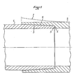
- a tubular steel joint for the petroleum industry which comprises a male element 1 and a female element 2.
- This female element 2 can be constituted by a sleeve which comprises at its right end a thread as at its left end or by the thickened end of a tube section.
- the male element 1 has an external frustoconical thread 3, while the female element 2 has an internal frustoconical thread 4 of corresponding shape.
- the male element 1 comprises a stop 5 for limiting screwing which is applied against the stop 6 for limiting screwing of the female element 2.
- the male element 1 Due to the fact that the male element 1 has at the threads 3 a diameter greater than the internal diameter of the threads 4 of the female element 2, as the male element 1 is screwed into the female element 2 (and this until the surfaces 5 and 6 come into contact), there is a widening of the diameter of the female element 2 which is represented by the dashed line curve 7 in FIG. 1.
- This trumpet deformation of the female element results in a longitudinal contraction of the external surface of the female element (in the direction of a generator) and in a transverse extension of this same external surface (in the direction perpendicular to the generatrices ).
- the curve 8 of the deformations which the external surface of the female element undergoes in this state is shown in broken lines in FIG. 2.
- the measurement of the longitudinal deformations of the surface of the female element is used using a strain gauge which is applied to the surface of the female element to determine the moment when the tightness of the joint must be stopped.
- the device which makes it possible to detect longitudinal surface deformations of the external surface of the female element is shown diagrammatically in perspective in FIG. 3.
- the female element 2 which is constituted by a sleeve and which has threads 4 inside which must engage manage the end of the male element 1. Also shown in broken lines is the stop 6 for screwing limitation as well as the trace 9 of the plane of the stop 6 for screwing limitation on the external surface of the female element 2 .
- the strain gauge is applied to the external surface of the female element 2 by means of the device 10 which is fixed to the female element by a strap 11 schematically shown.
- strain gauge is disposed at a distance D from the plane 6, 9 of the stop 6 for limiting screwing on the side opposite to that where the thread 4 of the female element is located.
- FIG. 4 schematically shows how the strain gauge 12 is applied to the external surface of the female element 2 by being fixed on a part 13 which slides in the block 10 fixed on the tube by the strap 11 and is constantly pushed back by the return spring 14.
- the strain gauge 12 is oriented so as to measure the longitudinal deformations (that is to say in a direction parallel to the axis of the tube).
- Figures 3 and 4 are only schematic and that the strain gauge 12 can be applied in different ways on the female element.
- this strain gauge 12 can be made integral with the jaw which holds the female element during the screwing of the male element which is then driven in rotation.
- FIG. 5 represents the theoretical evolution of these deformations which are measured by the strain gauge in the direction of the generators.
- the curve 15 of the deformations of the external surface of the female element has a descending part I which corresponds to the period during which the male element sinks into the female element causing the trumpet deformation of the surface external of the latter, which produces a longitudinal contraction of the external surface of the female element, while in the part II of the curve 15 which corresponds to the period which followed the contact of the screw-limiting stops, the bump 8a of curve 8 in FIG. 2 occurs gradually by causing a longitudinal extension of the external surface of the female element 2.
- FIG. 6 shows the curve of the longitudinal surface deformations of the female element in the case of a joint comprising a cylindrical thread and screwing limiting stops, the deformations being measured at a certain distance from the limiting stop. screwing on the side thereof which is opposite the threads.
- FIG. 7 shows the deformations of the external surface of the female element of an actual joint at the same time as the tightening torque.
- This curve corresponds to the screwing of a commercial joint which is a tubing of 88.9 mm (3 1/2 inches), of 13.7 kg / m (9.20 pounds per foot) and which is made with a steel grade 80 VC13.
- the longitudinal strain gauge is placed 7 mm from the plane of the screw-limiting stop on the other side of the threads.
- the undulations of the compression zone 1 are explained by the machining tolerances at the threads.
- the contraction reaches a minimum of -120 when the sealing surfaces and then the screw-limiting stops come into contact (approximately 260 °) to grow at a maximum extension of +780.
- the minimum value of compression is less than a given value (for example -200), it is certain that the hooping at the level of the threads has not been excessive.
- the method and the device according to the invention make it possible to carry out in a simple manner and economical checking correct screwing, which is a guarantee of proper functioning of the seal, that is to say of its strength and its tightness.
Landscapes
- Engineering & Computer Science (AREA)
- General Engineering & Computer Science (AREA)
- Mechanical Engineering (AREA)
- Mining & Mineral Resources (AREA)
- Geology (AREA)
- Life Sciences & Earth Sciences (AREA)
- Geochemistry & Mineralogy (AREA)
- Fluid Mechanics (AREA)
- Physics & Mathematics (AREA)
- General Life Sciences & Earth Sciences (AREA)
- Environmental & Geological Engineering (AREA)
- Non-Disconnectible Joints And Screw-Threaded Joints (AREA)
- Earth Drilling (AREA)
- Details Of Spanners, Wrenches, And Screw Drivers And Accessories (AREA)
- Measurement Of Length, Angles, Or The Like Using Electric Or Magnetic Means (AREA)
- Mutual Connection Of Rods And Tubes (AREA)
- Control Of Motors That Do Not Use Commutators (AREA)
- Pens And Brushes (AREA)
- Clamps And Clips (AREA)
Applications Claiming Priority (2)
| Application Number | Priority Date | Filing Date | Title |
|---|---|---|---|
| FR8415403A FR2571466B1 (fr) | 1984-10-08 | 1984-10-08 | Procede et dispositif pour effectuer le vissage d'un joint filete pour tube |
| FR8415403 | 1984-10-08 |
Publications (2)
| Publication Number | Publication Date |
|---|---|
| EP0178988A1 EP0178988A1 (fr) | 1986-04-23 |
| EP0178988B1 true EP0178988B1 (fr) | 1989-05-24 |
Family
ID=9308434
Family Applications (1)
| Application Number | Title | Priority Date | Filing Date |
|---|---|---|---|
| EP85401962A Expired EP0178988B1 (fr) | 1984-10-08 | 1985-10-08 | Procédé et dispositif pour effectuer le vissage d'un joint fileté pour tube muni d'une butée |
Country Status (16)
| Country | Link |
|---|---|
| US (2) | US4700576A (enExample) |
| EP (1) | EP0178988B1 (enExample) |
| JP (1) | JPS62500532A (enExample) |
| KR (1) | KR930003295B1 (enExample) |
| CN (1) | CN1003951B (enExample) |
| AU (1) | AU580097B2 (enExample) |
| BR (1) | BR8504992A (enExample) |
| CA (1) | CA1299349C (enExample) |
| DE (2) | DE3570481D1 (enExample) |
| ES (1) | ES8704610A1 (enExample) |
| FR (1) | FR2571466B1 (enExample) |
| MX (1) | MX163012B (enExample) |
| NO (1) | NO165310C (enExample) |
| SU (1) | SU1540661A3 (enExample) |
| WO (1) | WO1986002123A1 (enExample) |
| ZA (1) | ZA857754B (enExample) |
Families Citing this family (21)
| Publication number | Priority date | Publication date | Assignee | Title |
|---|---|---|---|---|
| US4957002A (en) * | 1989-02-27 | 1990-09-18 | Bilco Tools, Inc. | Method, system and device for determining quality of assembly of tool parts |
| GB9012498D0 (en) * | 1990-06-05 | 1990-07-25 | Dico Packaging Engineers Ltd | A device for measuring torque or force |
| US5402688A (en) * | 1993-03-17 | 1995-04-04 | Sumitomo Metal Industries, Ltd. | Method and apparatus for determining the tightened condition of a pipe joint |
| US5955679A (en) * | 1997-01-31 | 1999-09-21 | Liberty Technologies, Inc. | Device for measuring strain parameters of a generally cylindrical member of virtually any size |
| AU715952B1 (en) * | 1998-07-30 | 2000-02-10 | Hydril Company | Tubular joint wear indicator |
| US6009611A (en) * | 1998-09-24 | 2000-01-04 | Oil & Gas Rental Services, Inc. | Method for detecting wear at connections between pin and box joints |
| US6385837B1 (en) | 1999-04-05 | 2002-05-14 | Central Motor Wheel Co., Ltd. | Method and apparatus for fixedly connecting threaded tubes, and recording medium storing control program for practicing or controlling those method and apparatus |
| GB2353342A (en) * | 1999-08-17 | 2001-02-21 | Michael Douglas Seymour | Method of forming a connection between a tube and a fitting |
| SE522352C2 (sv) * | 2000-02-16 | 2004-02-03 | Sandvik Ab | Avlångt element för slående bergborrning och användning av stål för detta |
| WO2001065164A1 (en) * | 2000-02-29 | 2001-09-07 | Asahi Beer Engineering Ltd. | Expansion joint device |
| US6748808B2 (en) | 2001-08-14 | 2004-06-15 | Varco I/P, Inc. | Flaw detection in tubular members |
| US6622561B2 (en) | 2001-08-14 | 2003-09-23 | Varco I/P, Inc. | Tubular member flaw detection |
| US6578422B2 (en) | 2001-08-14 | 2003-06-17 | Varco I/P, Inc. | Ultrasonic detection of flaws in tubular members |
| AU2003243568A1 (en) * | 2002-06-17 | 2003-12-31 | Swagelok Company | Ultrasonic testing of fitting assembly for fluid conduits |
| US6745136B2 (en) | 2002-07-02 | 2004-06-01 | Varco I/P, Inc. | Pipe inspection systems and methods |
| US7001065B2 (en) * | 2003-05-05 | 2006-02-21 | Ray Dishaw | Oilfield thread makeup and breakout verification system and method |
| FR2860546B1 (fr) * | 2003-10-01 | 2006-01-27 | Vallourec Mannesmann Oil & Gas | Composant tubulaire muni d'elements filetes mutuellement orientes et procede pour le realiser |
| CN102162340A (zh) * | 2011-02-14 | 2011-08-24 | 江苏常宝钢管股份有限公司 | 高气密偏梯形螺纹套管连接结构的使用方法 |
| FR2999708B1 (fr) * | 2012-12-18 | 2014-12-05 | Vallourec Mannesmann Oil & Gas | Procede de controle d'un etat de vissage d'un joint filete tubulaire |
| JP2018059779A (ja) * | 2016-10-04 | 2018-04-12 | 東京瓦斯株式会社 | 締め付けトルク測定装置及び締め付けトルク測定方法 |
| RU2646280C2 (ru) * | 2016-12-02 | 2018-03-02 | Открытое акционерное общество "Завод бурового оборудования" | Отсоединительный переходник |
Family Cites Families (13)
| Publication number | Priority date | Publication date | Assignee | Title |
|---|---|---|---|---|
| US2094491A (en) * | 1934-07-20 | 1937-09-28 | Janata Rudolph | Screw thread joint |
| US2568940A (en) * | 1946-08-13 | 1951-09-25 | Texas Co | Strain measurement |
| US2637907A (en) * | 1946-11-30 | 1953-05-12 | Youngstown Sheet And Tube Co | Extensometer for cylindrical members |
| US3082621A (en) * | 1959-06-22 | 1963-03-26 | Soderholm Arne Olof | Extensometer |
| US3314156A (en) * | 1964-07-08 | 1967-04-18 | Exxon Production Research Co | Apparatus for use in making up pipe strings |
| US3368396A (en) * | 1964-09-14 | 1968-02-13 | Exxon Production Research Co | Assembling pipe strings with leak-tight joints |
| US3606664A (en) * | 1969-04-04 | 1971-09-21 | Exxon Production Research Co | Leak-proof threaded connections |
| US3745820A (en) * | 1969-04-04 | 1973-07-17 | Exxon Production Research Co | Leak proof threaded connections |
| US3791205A (en) * | 1972-02-04 | 1974-02-12 | D Hooker | Potted strain gauge |
| JPS5197457A (en) * | 1975-02-22 | 1976-08-27 | Yunitsutogata hizumigeeji | |
| DE3011739A1 (de) * | 1980-03-26 | 1981-10-01 | Sartorius GmbH, 3400 Göttingen | Verwendung von phenol-aldehydharzen zur entfernung von insbesondere harnpflichtigen stoffen aus fluessigkeiten |
| US4573359A (en) * | 1980-07-02 | 1986-03-04 | Carstensen Kenneth J | System and method for assuring integrity of tubular sections |
| US4473359A (en) * | 1981-09-22 | 1984-09-25 | Davis Robert R | Flexible coupling device |
-
1984
- 1984-10-08 FR FR8415403A patent/FR2571466B1/fr not_active Expired
-
1985
- 1985-10-08 BR BR8504992A patent/BR8504992A/pt not_active IP Right Cessation
- 1985-10-08 KR KR8507427A patent/KR930003295B1/ko not_active Expired - Lifetime
- 1985-10-08 JP JP60504473A patent/JPS62500532A/ja active Granted
- 1985-10-08 SU SU853964115A patent/SU1540661A3/ru active
- 1985-10-08 MX MX182A patent/MX163012B/es unknown
- 1985-10-08 WO PCT/FR1985/000281 patent/WO1986002123A1/fr not_active Ceased
- 1985-10-08 US US06/785,397 patent/US4700576A/en not_active Expired - Fee Related
- 1985-10-08 NO NO853990A patent/NO165310C/no unknown
- 1985-10-08 CN CN85108215.7A patent/CN1003951B/zh not_active Expired
- 1985-10-08 CA CA000492503A patent/CA1299349C/fr not_active Expired - Lifetime
- 1985-10-08 ZA ZA857754A patent/ZA857754B/xx unknown
- 1985-10-08 AU AU48385/85A patent/AU580097B2/en not_active Ceased
- 1985-10-08 ES ES548345A patent/ES8704610A1/es not_active Expired
- 1985-10-08 EP EP85401962A patent/EP0178988B1/fr not_active Expired
- 1985-10-08 DE DE8585401962T patent/DE3570481D1/de not_active Expired
- 1985-10-08 DE DE198585401962T patent/DE178988T1/de active Pending
-
1987
- 1987-08-27 US US07/090,230 patent/US4791816A/en not_active Expired - Fee Related
Also Published As
| Publication number | Publication date |
|---|---|
| NO165310B (no) | 1990-10-15 |
| KR860003443A (ko) | 1986-05-26 |
| CN1003951B (zh) | 1989-04-19 |
| US4700576A (en) | 1987-10-20 |
| EP0178988A1 (fr) | 1986-04-23 |
| ZA857754B (en) | 1986-06-25 |
| JPS62500532A (ja) | 1987-03-05 |
| MX163012B (es) | 1991-08-05 |
| ES548345A0 (es) | 1987-04-16 |
| SU1540661A3 (ru) | 1990-01-30 |
| US4791816A (en) | 1988-12-20 |
| BR8504992A (pt) | 1986-07-29 |
| JPH0353515B2 (enExample) | 1991-08-15 |
| CA1299349C (fr) | 1992-04-28 |
| WO1986002123A1 (fr) | 1986-04-10 |
| FR2571466A1 (fr) | 1986-04-11 |
| KR930003295B1 (en) | 1993-04-24 |
| FR2571466B1 (fr) | 1987-03-20 |
| DE3570481D1 (en) | 1989-06-29 |
| AU4838585A (en) | 1986-05-08 |
| NO853990L (no) | 1986-04-09 |
| CN85108215A (zh) | 1986-04-10 |
| NO165310C (no) | 1991-01-23 |
| DE178988T1 (de) | 1987-02-05 |
| AU580097B2 (en) | 1988-12-22 |
| ES8704610A1 (es) | 1987-04-16 |
Similar Documents
| Publication | Publication Date | Title |
|---|---|---|
| EP0178988B1 (fr) | Procédé et dispositif pour effectuer le vissage d'un joint fileté pour tube muni d'une butée | |
| CA1251926A (fr) | Procede pour determiner le couple de vissage d'un joint tubulaire comportant un filetage conique et une butee de limitation de vissage, utilisable dans l'industrie du petrole etdispositifs pour mettre en oeuvre ce procede | |
| FR2522144A1 (fr) | Procede et dispositif pour s'assurer du vissage correct d'un joint tubulaire comportant une butee de limitation de vissage | |
| EP0089253B1 (fr) | Joint pour tubes d'acier étanche aux pressions élevées et peu sensible au phénomène de grippage | |
| EP2935759B1 (fr) | Procede de controle d'un etat de vissage d'un joint filete tubulaire | |
| FR2736988A1 (fr) | Raccord a tube | |
| EP1462220B1 (fr) | Clé à serrage contrôlé | |
| EP0100259B1 (fr) | Dispositif de raccordement rapide de tubes et de cuvelages, notamment pour forage en mer | |
| EP0170553A1 (fr) | Procédé et dispositif d'usinage d'épaulements de joints pour tubes | |
| EP0522922A1 (fr) | Procédé et dispositif de contrôle par ultrasons de l'état de surface d'un alésage | |
| EP4314475B1 (fr) | Dimensionnement d'un jeu axial de filetage | |
| FR2529991A1 (enExample) | ||
| EP0159242B1 (fr) | Joint pour tubes d'acier, outillage et procédé pour obtenir une plus grande précision | |
| FR3008147A1 (fr) | Dispositif de serrage d'ecrou | |
| CA1105296A (fr) | Machine d'aboutage de conduites pour pose en eaux de toutes profondeurs | |
| FR2697610A1 (fr) | Dispositif de guidage et raccord d'extrémité remplaçable pour extrémités de canalisations flexibles utilisables en mer. | |
| EP0581678A1 (fr) | Dispositif de serrage d'un tuyau et embout de raccordement comprenant ce dispositif | |
| FR2620649A1 (fr) | Appareil pour serrer deux pieces en particulier en vue de leur soudage | |
| FR3071287A1 (fr) | Systeme de fixation a precontrainte calibree | |
| WO1985000634A1 (fr) | Pince de puissance pour le vissage des tiges de forage | |
| EP0046705A1 (fr) | Raccord entre une conduite plastique pour fluide sous pression et une conduite métallique | |
| FR3137735A1 (fr) | Ensemble tubulaire amélioré destiné à être raccordé à un deuxième tube | |
| EP1431644B1 (fr) | Dispositif de raccordement étanche entre un tuyau et un corps | |
| FR2806762A1 (fr) | Dispositif de fixation du type vis-ecrou a desserrage rapide | |
| BE699242A (enExample) |
Legal Events
| Date | Code | Title | Description |
|---|---|---|---|
| PUAI | Public reference made under article 153(3) epc to a published international application that has entered the european phase |
Free format text: ORIGINAL CODE: 0009012 |
|
| AK | Designated contracting states |
Kind code of ref document: A1 Designated state(s): BE DE FR GB IT NL SE |
|
| 17P | Request for examination filed |
Effective date: 19860627 |
|
| DET | De: translation of patent claims | ||
| 17Q | First examination report despatched |
Effective date: 19871006 |
|
| GRAA | (expected) grant |
Free format text: ORIGINAL CODE: 0009210 |
|
| AK | Designated contracting states |
Kind code of ref document: B1 Designated state(s): BE DE FR GB IT NL SE |
|
| REF | Corresponds to: |
Ref document number: 3570481 Country of ref document: DE Date of ref document: 19890629 |
|
| GBT | Gb: translation of ep patent filed (gb section 77(6)(a)/1977) | ||
| ITF | It: translation for a ep patent filed | ||
| PLBE | No opposition filed within time limit |
Free format text: ORIGINAL CODE: 0009261 |
|
| STAA | Information on the status of an ep patent application or granted ep patent |
Free format text: STATUS: NO OPPOSITION FILED WITHIN TIME LIMIT |
|
| 26N | No opposition filed | ||
| ITTA | It: last paid annual fee | ||
| PGFP | Annual fee paid to national office [announced via postgrant information from national office to epo] |
Ref country code: SE Payment date: 19920929 Year of fee payment: 8 |
|
| PGFP | Annual fee paid to national office [announced via postgrant information from national office to epo] |
Ref country code: GB Payment date: 19921002 Year of fee payment: 8 |
|
| PGFP | Annual fee paid to national office [announced via postgrant information from national office to epo] |
Ref country code: FR Payment date: 19921015 Year of fee payment: 8 |
|
| PGFP | Annual fee paid to national office [announced via postgrant information from national office to epo] |
Ref country code: NL Payment date: 19921031 Year of fee payment: 8 |
|
| PGFP | Annual fee paid to national office [announced via postgrant information from national office to epo] |
Ref country code: BE Payment date: 19921208 Year of fee payment: 8 |
|
| PGFP | Annual fee paid to national office [announced via postgrant information from national office to epo] |
Ref country code: DE Payment date: 19921222 Year of fee payment: 8 |
|
| PG25 | Lapsed in a contracting state [announced via postgrant information from national office to epo] |
Ref country code: GB Effective date: 19931008 |
|
| PG25 | Lapsed in a contracting state [announced via postgrant information from national office to epo] |
Ref country code: SE Effective date: 19931009 |
|
| REG | Reference to a national code |
Ref country code: GB Ref legal event code: 732E |
|
| PG25 | Lapsed in a contracting state [announced via postgrant information from national office to epo] |
Ref country code: BE Effective date: 19931031 |
|
| BERE | Be: lapsed |
Owner name: VALLOUREC Effective date: 19931031 |
|
| PG25 | Lapsed in a contracting state [announced via postgrant information from national office to epo] |
Ref country code: NL Effective date: 19940501 |
|
| GBPC | Gb: european patent ceased through non-payment of renewal fee |
Effective date: 19931008 |
|
| NLV4 | Nl: lapsed or anulled due to non-payment of the annual fee | ||
| PG25 | Lapsed in a contracting state [announced via postgrant information from national office to epo] |
Ref country code: FR Effective date: 19940630 |
|
| PG25 | Lapsed in a contracting state [announced via postgrant information from national office to epo] |
Ref country code: DE Effective date: 19940701 |
|
| REG | Reference to a national code |
Ref country code: FR Ref legal event code: ST |
|
| EUG | Se: european patent has lapsed |
Ref document number: 85401962.7 Effective date: 19940510 |