EP0178458A2 - Enrouleur - Google Patents
Enrouleur Download PDFInfo
- Publication number
- EP0178458A2 EP0178458A2 EP85111507A EP85111507A EP0178458A2 EP 0178458 A2 EP0178458 A2 EP 0178458A2 EP 85111507 A EP85111507 A EP 85111507A EP 85111507 A EP85111507 A EP 85111507A EP 0178458 A2 EP0178458 A2 EP 0178458A2
- Authority
- EP
- European Patent Office
- Prior art keywords
- side flange
- winding
- winding device
- bushing
- individual segments
- Prior art date
- Legal status (The legal status is an assumption and is not a legal conclusion. Google has not performed a legal analysis and makes no representation as to the accuracy of the status listed.)
- Granted
Links
Images

Classifications
-
- B—PERFORMING OPERATIONS; TRANSPORTING
- B65—CONVEYING; PACKING; STORING; HANDLING THIN OR FILAMENTARY MATERIAL
- B65H—HANDLING THIN OR FILAMENTARY MATERIAL, e.g. SHEETS, WEBS, CABLES
- B65H75/00—Storing webs, tapes, or filamentary material, e.g. on reels
- B65H75/02—Cores, formers, supports, or holders for coiled, wound, or folded material, e.g. reels, spindles, bobbins, cop tubes, cans, mandrels or chucks
- B65H75/18—Constructional details
- B65H75/22—Constructional details collapsible; with removable parts
- B65H75/2209—Constructional details collapsible; with removable parts collapsible by use of hinged or slidable parts; foldable without removing parts
-
- B—PERFORMING OPERATIONS; TRANSPORTING
- B65—CONVEYING; PACKING; STORING; HANDLING THIN OR FILAMENTARY MATERIAL
- B65H—HANDLING THIN OR FILAMENTARY MATERIAL, e.g. SHEETS, WEBS, CABLES
- B65H54/00—Winding, coiling, or depositing filamentary material
- B65H54/56—Winding of hanks or skeins
- B65H54/58—Swifts or reels adapted solely for the formation of hanks or skeins
-
- B—PERFORMING OPERATIONS; TRANSPORTING
- B65—CONVEYING; PACKING; STORING; HANDLING THIN OR FILAMENTARY MATERIAL
- B65H—HANDLING THIN OR FILAMENTARY MATERIAL, e.g. SHEETS, WEBS, CABLES
- B65H2701/00—Handled material; Storage means
- B65H2701/50—Storage means for webs, tapes, or filamentary material
- B65H2701/51—Cores or reels characterised by the material
- B65H2701/515—Cores or reels characterised by the material assembled from parts made of different materials
Definitions
- the invention relates to a winding device as specified in the preamble of the main claim.
- Known winding devices use winding heads on which the beginning of the winding material must be clamped by hand before the winding process.
- wedge-shaped cutouts are provided on the winding core as a clamping device, into which the respective beginning of the winding material is inserted and clamped.
- the coiled cable, hose or profile rings that were wound up by hand or with a motor drive must now be removed manually. This manual work is time consuming and monotonous.
- the invention has for its object to provide a motor-driven winding device with which the winding material can be processed at least largely by machine.
- the winding head which consists of a first and a second side flange, is preferably pushed or pushed apart by machine.
- the core of the winding head which consists of a plurality of swiveling individual segments and which is fastened to the first side flange, can be tapered by means of a pneumatic or hydraulic drive after the second side flange has been removed and after the winding material has set.
- the end winding can also be designed so that the end winding tapers automatically when the second side flange is removed.
- the individual segments of the core swivel inwards so that the wound material can slide off or be stripped off.
- An automatic removal of the winding material can be ensured by a swiveling device with which the first side flange and thus the winding core is swiveled forward so that the winding material falls off.
- the clamping device which holds the start of the winding material during the winding process, opens when the second side flange is removed.
- the clamping device is preferably designed such that a recess is provided on at least one of the individual segments in the region of its ends facing the second side flange, into which the beginning of the winding material protrudes, and that at least one resilient clamping element is arranged on the second side flange, which element is attached when the second one is attached Side flange jammed the beginning of the material to be wound in the recess. The beginning of the material to be wound is pressed onto the edge of the recess.
- the second side flange is fastened axially displaceably on a displacement unit, and that the displacement unit has a support frame which can be displaced parallel to the axis of rotation of the winding head by means of a pneumatic cylinder and on which the second side flange is rotatably mounted.
- the second side flange can be provided with an electromagnetic braking device.
- the pivotable individual segments of the first side flange are arranged in such a way that when the second side flange is plugged on, they are pressed outward via hinge plates until the surface of the winding core runs parallel to the axis of rotation. If the second side flange is removed after the winding process has ended, a spiral spring presses the swiveling individual segments back inwards. The swivel joints of the individual segments are located outside the winding core.
- the drive shaft of the first side flange is rigidly connected to the side disk which limits the winding core on one side and projects into the interior of the winding core.
- There is a slidably mounted bushing on the drive shaft which is connected to the individual segments by means of link plates. If the bushing is pressed inwards against the spring by a spring force, the individual segments are thereby pressed outwards via the joint plates until the surface of the winding core runs parallel to the drive shaft.
- the socket located on the drive shaft is actuated by a second socket of the second side flange, which is likewise resiliently mounted, when the second side flange is put on.
- the motor intended to drive the winding head is preferably a stepping motor with which the recesses provided for receiving the start of the winding material can be positioned exactly.
- a gripper arm it is possible to mechanically insert the beginning of the winding material to be threaded into the recess on the winding head by means of a gripper arm.
- the second side flange is then slipped onto the first side flange in the axial direction, for example by means of a pneumatic drive. So that the clamping elements arranged on the second side flange and the recesses of the first side flange always match, the second side flange is held in the corresponding position by means of a braking device, so that it cannot rotate during the axial displacements.
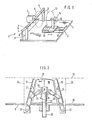
- a displacement unit 2 and a swivel device 3 are mounted on a base plate 1.
- a first side flange 5 of a winding head 6, which is only indicated here, is mounted on a pivot axis 4 of the pivot device 3.
- the first side flange 5 is driven by a stepping motor 7.
- a pivot arm 8 is attached to the pivot axis 4 and can be actuated by means of a cylinder 9.
- a winding material located on the winding core (not shown here) of the first side flange can be thrown off the side flange 5 in this way.
- the displacement unit 2 consists essentially of a support frame 10 which can be displaced parallel to the drive axis of the first side flange 5 by means of a cylinder 11.
- Two guide rods 12 are shown as guide elements in the drawing for the axial displacement of the support frame 10.
- the second side flange 13 of the winding head 6 is rotatably mounted, which, however, can be locked or held in any position by means of an electromagnetic brake 14.
- the two side flanges 5 and 13 are only indicated here and are in the open position, since the second side flange 13 has been withdrawn from the first side flange 5.
- the second side flange 13 can be brought into the position not shown here and onto the first one Side flange 5 are pushed on.
- the structure of the first side flange 5 can be seen in particular in FIG. This consists essentially of a lateral disc 15 and the winding core 16 which is delimited on one side by the disc 15.
- the second side flange 13 is shown in FIG. 2 with a broken line.
- the winding core 16 of the first side flange 5 consists of a plurality of individual segments 17, 18, 19, which are here in the inwardly pivoted position, as occurs when the second side flange 13 is removed. However, if the second side flange 13 is in the position shown with broken lines, the individual segments 17 to 19 are brought into the position 20 shown with broken lines.
- the individual segments 17 to 19 are attached to struts 21 which are pivotally mounted in pivot joints 22 on the side flange.
- joint straps 23 are fastened to the struts, the other ends of which are fastened to an axially displaceable bush 24.
- the bushing 24 is seated on an extension 25 of the drive shaft 26, which extends into the interior of the winding core 16.
- the bushing 24 is resiliently supported with respect to the disk 15 by means of a spiral spring 27.
- the individual segment 18 has a cutout 28 into which the beginning of the material to be wound is inserted before the winding process.
- the second side flange 13 can either still be completely removed from the first side flange 5 or it is only pushed onto the first side flange 5 to such an extent that the clamping elements in the region of the cutout 28 are not yet effective. In the latter case, however, the individual segments 17 to 19 can already be pivoted into position 20.
- the second side flange 13 can then be pushed on completely so that it lies directly against the winding core 16 and laterally delimits it.
- FIG. 3 shows the side flange 5 with winding core 16, in which the individual segments 17 to 19 are in the vertical position 20.
- the meaning of the reference numbers used here corresponds to that of FIG. 2.
- the entire winding head 6 and thus also the first side flange 5 can be brought into a defined position by means of the stepping motor 7, so that the cutout 28 is always arranged in the same position for the threading process.
- the threading of the winding material start 29 can take place automatically by means of a threading device, not shown here.
- the disc 15 of the side flange 5 has symmetrical Arranged, radially extending cutouts 30, which enable the wound winding material 31, which is only indicated here, to be tied off before being removed from the winding core 16.
- FIG 4 the structure of the second side flange 13 is visible, which for clamping the winding-beginning clamping elements 29 '32, 33 has.
- the drawing shows two different types of clamping elements 32, 33.
- the clamping element 32 is pressed down by a compression spring 34 in the direction of the arrow.
- the chamber 35 in which a part of the clamping element 32 and the compression spring 34 are arranged, is preferably circular in cross section.
- the other clamping element 33 is pivotally mounted about an axis 36 and is moved in the arrow direction indicated by means of a tension spring 37.
- the holder 38 provided for the clamping element 33 has a stop 39 which limits the mobility of the clamping element 33.
- the second side flange 13 has an axis 40 which is connected to an electromagnetic brake 14.
- the extension 41 of the axis 40 protruding into the winding core 16 of the winding head also serves as a guide element for a resiliently arranged bushing 42.
- the bushing 42 is in the direction of the arrow opposite the disc 44 of the second side flange 13 serving as a lateral limitation pushed away.
- the individual segments 17 to 19 are first brought into the position shown in FIG. 4 before the second side flange 13 abuts the winding core 16.
- the bushing 42 is only pressed upward against the spring force of the spiral spring 43 when the bushing 24 has reached its lower end position.
- the clamping elements 32, 33 can be designed such that they only become effective after the bushing 24 has reached its lower end position and the side flange 13 is pressed further against the winding core 16.
- an embodiment is shown, which can also be modified so that the bushing 24 can be actuated by means of a special drive completely independently of the removal of the second side flange 13.
- a pneumatic cylinder can be used as a drive for this purpose, which displaces the bushing 24 in the axial direction.
- This pneumatic drive can also engage the shaft 26, which can be rigidly connected to the bushing 24. In this case, the shaft-e 26 would have to be guided axially displaceably through the side flange 15, the drive for the winding process acting on the flange hatched in FIG. 2.
- Such an embodiment with a separate drive for the bushing 24 would have the advantage that the winding material which had already been wound up would still sit firmly on the winding core when the second side flange 13 was removed, where it was removed before being thrown off. could be bound. During the setting process, it would be ensured that the material to be wound does not change its ring shape. Only after the setting had been carried out would the bushing 24 be shifted and the winding core diameter would thus be tapered.
Landscapes
- Storage Of Web-Like Or Filamentary Materials (AREA)
- Winding Of Webs (AREA)
- Manufacture Of Motors, Generators (AREA)
Applications Claiming Priority (2)
| Application Number | Priority Date | Filing Date | Title |
|---|---|---|---|
| DE3438179 | 1984-10-18 | ||
| DE19843438179 DE3438179A1 (de) | 1984-10-18 | 1984-10-18 | Wickelvorrichtung |
Publications (3)
| Publication Number | Publication Date |
|---|---|
| EP0178458A2 true EP0178458A2 (fr) | 1986-04-23 |
| EP0178458A3 EP0178458A3 (en) | 1987-01-21 |
| EP0178458B1 EP0178458B1 (fr) | 1989-08-09 |
Family
ID=6248192
Family Applications (1)
| Application Number | Title | Priority Date | Filing Date |
|---|---|---|---|
| EP85111507A Expired EP0178458B1 (fr) | 1984-10-18 | 1985-09-11 | Enrouleur |
Country Status (3)
| Country | Link |
|---|---|
| US (1) | US4674701A (fr) |
| EP (1) | EP0178458B1 (fr) |
| DE (1) | DE3438179A1 (fr) |
Cited By (2)
| Publication number | Priority date | Publication date | Assignee | Title |
|---|---|---|---|---|
| EP0554230A2 (fr) * | 1992-01-20 | 1993-08-04 | Tecnologia Del Automatismo, S.A. | Perfectionnements aux machines d'enroulement et de ficelage |
| CN103950774A (zh) * | 2014-05-08 | 2014-07-30 | 李培培 | 一种缠绕机的薄膜涨紧辊 |
Families Citing this family (6)
| Publication number | Priority date | Publication date | Assignee | Title |
|---|---|---|---|---|
| US4865261A (en) * | 1987-11-03 | 1989-09-12 | United Technologies Automotive, Inc. | Spooler system with temporary, larger diameter spooling surface |
| US4934617A (en) * | 1989-02-13 | 1990-06-19 | Lindgren Peter B | Apparatus for forming a coil of line |
| US4936522A (en) * | 1989-03-31 | 1990-06-26 | New Jersey Machine Inc. | Collapsible rewind spindle |
| IT1302794B1 (it) * | 1998-11-04 | 2000-09-29 | Danieli & C Ohg Sp | Rocchettatrice per prodotti laminati |
| CN101177218B (zh) * | 2006-11-07 | 2011-10-19 | 关著铭 | 一种无芯线盘精密绕线机 |
| CN103693513A (zh) * | 2013-12-27 | 2014-04-02 | 吴江市华宏纺织丝绸有限公司 | 一种可调式纺织筒 |
Citations (12)
| Publication number | Priority date | Publication date | Assignee | Title |
|---|---|---|---|---|
| GB105682A (fr) * | 1900-01-01 | |||
| US760323A (en) * | 1902-03-15 | 1904-05-17 | Morgan Construction Co | Rod or wire reeling or coiling device. |
| US800579A (en) * | 1904-12-31 | 1905-09-26 | Iroquois Machine Company | Coiling apparatus. |
| US872826A (en) * | 1906-10-19 | 1907-12-03 | Jed N Landon | Reel. |
| US1461736A (en) * | 1922-12-04 | 1923-07-17 | William A Prentiss | Collapsible spool |
| US3236465A (en) * | 1964-02-26 | 1966-02-22 | Hanscom & Co Inc H F | Reeling apparatus |
| GB1102770A (en) * | 1964-12-14 | 1968-02-07 | Joseph Alphonsus Maria De Bruy | Improvements in or relating to reels for supporting coils |
| US4026483A (en) * | 1974-01-25 | 1977-05-31 | Skaltek Ab | Device for an apparatus for coiling of cable, wire, wire rope or the like |
| DE2431515B2 (de) * | 1973-07-03 | 1979-01-11 | N.V. Bekaert S.A., Zwevegem (Belgien) | Wickelmaschine |
| US4310126A (en) * | 1980-10-07 | 1982-01-12 | Norco Landscaping & Maintenance Co., Inc. | Winding apparatus for plastic line |
| DD158540A1 (de) * | 1981-05-11 | 1983-01-19 | Wilfried Gruner | Spulentraeger fuer angetriebene scheibenspulen an hohlseidespinnmaschinen |
| US4483490A (en) * | 1982-04-27 | 1984-11-20 | Maschinenfabrik Niehoff Kg | Individual coil winder with automatic coil change |
Family Cites Families (9)
| Publication number | Priority date | Publication date | Assignee | Title |
|---|---|---|---|---|
| US1451131A (en) * | 1920-06-26 | 1923-04-10 | Weber Henry | Adjustable reel |
| US2529185A (en) * | 1946-11-21 | 1950-11-07 | American Steel & Wire Co | Collapsible take-up spool |
| US2866606A (en) * | 1953-10-20 | 1958-12-30 | Chicago Bridge & Iron Co | Welding rod reel |
| US2839258A (en) * | 1955-11-02 | 1958-06-17 | Delbert G Jacobson | Wire winding spool mechanism |
| US2971721A (en) * | 1957-06-26 | 1961-02-14 | Rome Cable Corp | Construction of coil blocks |
| US3275261A (en) * | 1964-03-23 | 1966-09-27 | Hanscom & Co Inc H F | Collapsible reel |
| FR2256665A5 (en) * | 1973-12-28 | 1975-07-25 | Tauzin | Variable diameter telephone cable reel - has hub segments linked to sliding sleeve on spindle |
| DE2644084C3 (de) * | 1976-09-30 | 1981-10-01 | Krupp Stahl Ag, 4630 Bochum | Haspel für Bandmaterial |
| DE2912806C2 (de) * | 1979-03-30 | 1983-03-31 | Industriewerk Nachf. Seifert & Co Kg, 8632 Neustadt | Zerlegbare Drahtspule |
-
1984
- 1984-10-18 DE DE19843438179 patent/DE3438179A1/de active Granted
-
1985
- 1985-09-11 EP EP85111507A patent/EP0178458B1/fr not_active Expired
- 1985-09-26 US US06/780,443 patent/US4674701A/en not_active Expired - Fee Related
Patent Citations (12)
| Publication number | Priority date | Publication date | Assignee | Title |
|---|---|---|---|---|
| GB105682A (fr) * | 1900-01-01 | |||
| US760323A (en) * | 1902-03-15 | 1904-05-17 | Morgan Construction Co | Rod or wire reeling or coiling device. |
| US800579A (en) * | 1904-12-31 | 1905-09-26 | Iroquois Machine Company | Coiling apparatus. |
| US872826A (en) * | 1906-10-19 | 1907-12-03 | Jed N Landon | Reel. |
| US1461736A (en) * | 1922-12-04 | 1923-07-17 | William A Prentiss | Collapsible spool |
| US3236465A (en) * | 1964-02-26 | 1966-02-22 | Hanscom & Co Inc H F | Reeling apparatus |
| GB1102770A (en) * | 1964-12-14 | 1968-02-07 | Joseph Alphonsus Maria De Bruy | Improvements in or relating to reels for supporting coils |
| DE2431515B2 (de) * | 1973-07-03 | 1979-01-11 | N.V. Bekaert S.A., Zwevegem (Belgien) | Wickelmaschine |
| US4026483A (en) * | 1974-01-25 | 1977-05-31 | Skaltek Ab | Device for an apparatus for coiling of cable, wire, wire rope or the like |
| US4310126A (en) * | 1980-10-07 | 1982-01-12 | Norco Landscaping & Maintenance Co., Inc. | Winding apparatus for plastic line |
| DD158540A1 (de) * | 1981-05-11 | 1983-01-19 | Wilfried Gruner | Spulentraeger fuer angetriebene scheibenspulen an hohlseidespinnmaschinen |
| US4483490A (en) * | 1982-04-27 | 1984-11-20 | Maschinenfabrik Niehoff Kg | Individual coil winder with automatic coil change |
Cited By (4)
| Publication number | Priority date | Publication date | Assignee | Title |
|---|---|---|---|---|
| EP0554230A2 (fr) * | 1992-01-20 | 1993-08-04 | Tecnologia Del Automatismo, S.A. | Perfectionnements aux machines d'enroulement et de ficelage |
| EP0554230A3 (en) * | 1992-01-20 | 1993-12-29 | Tecnologia Del Automatismo S A | Improvements in winding and tying machines |
| ES2067349A2 (es) * | 1992-01-20 | 1995-03-16 | Tecnologia Del Automatismo S L | Mejoras en maquinas devanadoras y atadoras. |
| CN103950774A (zh) * | 2014-05-08 | 2014-07-30 | 李培培 | 一种缠绕机的薄膜涨紧辊 |
Also Published As
| Publication number | Publication date |
|---|---|
| DE3438179A1 (de) | 1986-04-30 |
| US4674701A (en) | 1987-06-23 |
| EP0178458A3 (en) | 1987-01-21 |
| EP0178458B1 (fr) | 1989-08-09 |
| DE3438179C2 (fr) | 1989-11-02 |
Similar Documents
| Publication | Publication Date | Title |
|---|---|---|
| DE3322444A1 (de) | Vorrichtung zum wechseln von werkzeugen | |
| DE3315568A1 (de) | Verfahren und vorrichtung zum blockieren und freigeben einer bohrstange mit im wesentlichen senkrechter achse | |
| EP0142794A2 (fr) | Dispositif de support de bobines | |
| DE4132998C2 (de) | Ansaug- und Transportvorrichtung | |
| EP0178458B1 (fr) | Enrouleur | |
| EP0744480B1 (fr) | Dispositif de fausse torsion | |
| DE1777294A1 (de) | Werkzeugmaschine | |
| DE3816593C2 (fr) | ||
| DE3315569A1 (de) | Verfahren und maschine zur manipulation von bohrstangen | |
| DE2736344A1 (de) | Vorrichtung zum steuern des abwickelns von draht u.dgl. von einer spule | |
| CH685622A5 (de) | Spulenhülsenaufnahmevorrichtung. | |
| DE10201384B4 (de) | Reibkupplungseinrichtung | |
| DE102007006593A1 (de) | Kabelbearbeitungseinrichtung mit mehreren Bearbeitungsstationen zur Konfektionierung eines Kabels | |
| DE3005667C2 (fr) | ||
| DE2745610C3 (de) | Stapelfaserschneidmaschine | |
| DE3323873A1 (de) | Abwickelvorrichtung fuer adern von spulen in der kabelindustrie | |
| EP0400530A2 (fr) | Dispositif de tronçonnage de pièces | |
| DE1560611A1 (de) | Verbesserungen an Tragvorrichtungen fuer Aufwickelspulen in Textilmaschinen | |
| DE3021121C2 (de) | Vorrichtung zum Auflegen und Spannen eines Endlosriemens einer Spinn- und Zwirnmaschine | |
| DE2624169B2 (de) | Vorrichtung und verfahren zum kontinuierlichen aufwickeln eines drahtes | |
| DD276041A1 (de) | Einrichtung zur befestigung eines drahtendes einer mit draht gefuellten spule | |
| DE4002924C2 (fr) | ||
| DE2217522A1 (de) | Seilandrueckvorrichtung | |
| DE3209881A1 (de) | Trag- und stuetzscheibe zum unterstuetzen und abstuetzen der schleifmittelbahn bei schleifvorrichtungen zum bearbeiten von werkstuecken aus holz oder aehnlichem material durch reibschleifen | |
| DE8319129U1 (de) | Abwickelvorrichtung für Adern von Spulen in der Kabelindustrie |
Legal Events
| Date | Code | Title | Description |
|---|---|---|---|
| PUAI | Public reference made under article 153(3) epc to a published international application that has entered the european phase |
Free format text: ORIGINAL CODE: 0009012 |
|
| AK | Designated contracting states |
Kind code of ref document: A2 Designated state(s): AT BE CH DE FR GB IT LI LU NL SE |
|
| RBV | Designated contracting states (corrected) |
Designated state(s): FR GB IT |
|
| PUAL | Search report despatched |
Free format text: ORIGINAL CODE: 0009013 |
|
| AK | Designated contracting states |
Kind code of ref document: A3 Designated state(s): FR GB IT |
|
| 17P | Request for examination filed |
Effective date: 19870502 |
|
| 17Q | First examination report despatched |
Effective date: 19880215 |
|
| RAP1 | Party data changed (applicant data changed or rights of an application transferred) |
Owner name: KABELMETAL ELECTRO GMBH |
|
| ITF | It: translation for a ep patent filed |
Owner name: DE DOMINICIS & MAYER S.R.L. |
|
| GRAA | (expected) grant |
Free format text: ORIGINAL CODE: 0009210 |
|
| AK | Designated contracting states |
Kind code of ref document: B1 Designated state(s): FR GB IT |
|
| GBT | Gb: translation of ep patent filed (gb section 77(6)(a)/1977) | ||
| ET | Fr: translation filed | ||
| PLBE | No opposition filed within time limit |
Free format text: ORIGINAL CODE: 0009261 |
|
| STAA | Information on the status of an ep patent application or granted ep patent |
Free format text: STATUS: NO OPPOSITION FILED WITHIN TIME LIMIT |
|
| 26N | No opposition filed | ||
| ITTA | It: last paid annual fee | ||
| PGFP | Annual fee paid to national office [announced via postgrant information from national office to epo] |
Ref country code: GB Payment date: 19920828 Year of fee payment: 8 |
|
| PGFP | Annual fee paid to national office [announced via postgrant information from national office to epo] |
Ref country code: FR Payment date: 19920928 Year of fee payment: 8 |
|
| PG25 | Lapsed in a contracting state [announced via postgrant information from national office to epo] |
Ref country code: GB Effective date: 19930911 |
|
| GBPC | Gb: european patent ceased through non-payment of renewal fee |
Effective date: 19930911 |
|
| PG25 | Lapsed in a contracting state [announced via postgrant information from national office to epo] |
Ref country code: FR Free format text: LAPSE BECAUSE OF NON-PAYMENT OF DUE FEES Effective date: 19940531 |
|
| REG | Reference to a national code |
Ref country code: FR Ref legal event code: ST |