EP0178239B2 - Procédé de transformation d'une machine de récolte pour l'amener d'une position de travail dans une position de transport, et machine de récolte utilisant ce procédé - Google Patents
Procédé de transformation d'une machine de récolte pour l'amener d'une position de travail dans une position de transport, et machine de récolte utilisant ce procédé Download PDFInfo
- Publication number
- EP0178239B2 EP0178239B2 EP85440050A EP85440050A EP0178239B2 EP 0178239 B2 EP0178239 B2 EP 0178239B2 EP 85440050 A EP85440050 A EP 85440050A EP 85440050 A EP85440050 A EP 85440050A EP 0178239 B2 EP0178239 B2 EP 0178239B2
- Authority
- EP
- European Patent Office
- Prior art keywords
- transport
- wheels
- working
- harvesting machine
- draw
- Prior art date
- Legal status (The legal status is an assumption and is not a legal conclusion. Google has not performed a legal analysis and makes no representation as to the accuracy of the status listed.)
- Expired - Lifetime
Links
Images

Classifications
-
- A—HUMAN NECESSITIES
- A01—AGRICULTURE; FORESTRY; ANIMAL HUSBANDRY; HUNTING; TRAPPING; FISHING
- A01D—HARVESTING; MOWING
- A01D75/00—Accessories for harvesters or mowers
- A01D75/002—Carriers for the transport of harvesters or mowers
-
- A—HUMAN NECESSITIES
- A01—AGRICULTURE; FORESTRY; ANIMAL HUSBANDRY; HUNTING; TRAPPING; FISHING
- A01B—SOIL WORKING IN AGRICULTURE OR FORESTRY; PARTS, DETAILS, OR ACCESSORIES OF AGRICULTURAL MACHINES OR IMPLEMENTS, IN GENERAL
- A01B73/00—Means or arrangements to facilitate transportation of agricultural machines or implements, e.g. folding frames to reduce overall width
- A01B73/005—Means or arrangements to facilitate transportation of agricultural machines or implements, e.g. folding frames to reduce overall width for endwise transportation, i.e. the direction of transport being substantially perpendicular to the direction of agricultural operation
Definitions
- the present invention relates to a method of transforming a harvesting machine in order to bring it from a working position in which the longitudinal axis of its body extends transversely to the working direction, in a position of transport in which the longitudinal axis of its body extends parallel, or at least substantially parallel to the direction of transport while remaining coupled to the tractor.
- a harvesting machine comprising a body which is supported at work on two wheels extending to the rear part of said body, and a drawbar connected to the body by means of a hinge d 'axis directed upwards, drawbar by means of which the harvesting machine can be hooked to the coupling device of a tractor.
- the body of this known harvesting machine comprises a chassis which rolls on the ground by means of two wheels and a cutter bar extending in the working position in front of said chassis. This cutter bar is linked to the chassis by means of connecting rods forming a deformable parallelogram.
- a lifting device with hydraulic cylinders acts on said parallelogram to raise the cutter bar ( Figure 1).
- the chassis meanwhile, consists of a main chassis and a movable auxiliary chassis which supports said main chassis.
- This mobile auxiliary chassis comprises a first structure supporting the main chassis by means of a vertical pivot shaft and a second structure supporting the first structure and said wheels.
- the first structure comprises a tubular member and the second structure a cylindrical member capable of rotating inside the tubular member. At each of its ends extending outside the tubular member, the cylindrical member is provided with an arm, at the free end of which one of said wheels is arranged.
- This known harvesting machine additionally comprises a certain number of pivoting control devices produced in the form of hydraulic cylinders.
- a first hydraulic cylinder acts between the body of the machine and the drawbar to bring this drawbar into its working positions ( Figures 3 and 8) and into its transport position ( Figure 6).
- a second hydraulic cylinder controls the pivoting of the mobile auxiliary chassis relative to the main chassis around the vertical pivot shaft to bring this mobile auxiliary chassis into its working position ( Figure 3) and into its transport position ( Figure 6).
- a third hydraulic cylinder pivots the cylindrical member in the tubular member, which allows the chassis to be moved away from the ground ( Figure 7).
- the aim of the present invention is to eliminate the drawbacks of this known method and of this harvesting machine.
- the phase of lifting the body to bring it into a high position and the phase of positioning the two transport wheels are carried out simultaneously, or at least substantially simultaneously.
- the transfer of the weight of the body of the two working wheels onto the two transport wheels and the pivoting of the drawbar from the working position to the transport takes place simultaneously, or at least substantially simultaneously.
- the method according to the invention may include an additional phase which consists in putting in place between the drawbar in the transport position and the body of the additional connecting means preventing the rocking of said body during transport.
- This additional connection is intended to prevent the body of the machine from swinging about the axis joining the points of contact of the transport wheels with the ground, which would very significantly stress the articulation linking the drawbar to the body of the machine.
- the transport wheels are brought into the transport position or the rest position using control means. Thanks to this feature, all the operations necessary to bring the harvesting machine from the working position to the transport position and vice versa can be done without the user having to get off the tractor. The ease of use of the machine and the speed of processing are further improved.
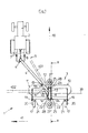
- the harvesting machine (1) is coupled during work and transport to a tractor (2). It consists of a body (3) and a drawbar (4). At its front (5), the drawbar (4) is provided with a coupling and transmission device (6) known to those skilled in the art. This device (6) allows the coupling of the machine (1) to the coupling system (7) of the tractor (2) and transmits the movement that it receives from the tractor (2) via a shaft to universal joints (8), to the drive members of the working tools of the machine (1).
- the body (3) of the machine (1) is formed by three main sub-assemblies: an intermediate structure (9) and two groups of work tools (10, 11) located respectively on either side of this intermediate structure (9).
- the drawbar (4) can pivot relative to the intermediate structure (9) so that it can take different positions relative to the intermediate structure (9).
- the drawbar (4) as shown in strong lines in Figure 1, is in a working position. In dashed lines, another possible working position (401) is shown and in broken lines, a transport position (402).
- the position of the drawbar (4) relative to the intermediate structure (9) is determined by extendable and retractable means such as the hydraulic cylinder (14) for example.
- extendable and retractable means such as the hydraulic cylinder (14) for example.
- one end of the hydraulic cylinder (14) is hingedly mounted on the drawbar (4) which for this purpose has a yoke (15), while the other end of said hydraulic cylinder (14) is mounted articulated on the body (3) of the machine (1) which also includes for this purpose a yoke (16).
- each group of working tools (10,11) comprises a yoke (19) in which is articulated a suspension arm (20) at the free end of which is linked the corresponding working wheel (17). Thanks to these articulations, the position of each wheel (17) can be modified relative to the corresponding group of working tools (10, 11). This therefore makes it possible to modify the position of the body (3) of the machine (1) relative to the ground.
- Each group of working tools (10, 11) additionally comprises means for guiding the harvest (21, 22).
- the intermediate structure (9) has a yoke (23, 24) in which an arm (25) is articulated around an axis (26) (see Figure 2) running parallel or to the less substantially parallel to the direction of transport (41).
- each arm (25) is provided with a transport wheel (27).
- the transport wheels (27) do not touch the ground and they are held in this position thanks to a lock (28) which prevents rotation of the arm ( 25) in the yoke (23, 24).
- the transport wheels (27) are in a position in which they do not interfere with the harvesting operation. Indeed, at the rear, the transport wheel (27) extends between the two crop guide means (22), while at the front, the transport wheel (27) extends relatively anterior to the working area of the machine tools (1).
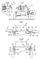
- Figure 2 shows a sectional side view of the body (3) of the machine (1).
- the crop guide means (21, 22) have been removed for better understanding.
- the machine (1) is in the example described, a mower-conditioner.
- the working tools are composed of cutting heads (29) and gripping and packaging tools (30).
- This figure also shows the working wheels (17) and the transport wheels (27).
- the working wheels (17) it can be seen that the end of the suspension arm (20) remote from the wheel (17) enters the yoke (19) which extends to the lower part of the body ( 3) of the machine (1). Between the suspension arm (20) and said body (3) extends an extendable and retractable device such as a hydraulic cylinder (31).
- an extendable and retractable device such as a hydraulic cylinder (31).
- the transport wheels (27) these being in the rest position, that is to say distant from the ground (32). They are held in this position, as said above, by a bolt (28) which passes through the yoke (23 or 24) and the arm (25) of part.
- the yokes (23, 24) have a hole (33.
- These yokes (23, 24) also have a second hole (34) into which the lock (28) will be inserted to hold the transport wheels (27) ) in the transport position.
- These yokes (23, 24) have, in addition to the high stops (35) and low stops (36). Thanks to these, it is relatively easy for the operator to raise or lower the transport wheels (27) Indeed, when the arm (25) abuts against the high stop (35) or the low stop (36), the latch (28) can be introduced without difficulty into the corresponding holes.
- the length of the body (3) of the machine (1) measured in a direction perpendicular to the working direction (18), is greater than the width of the body (3) of the machine (1 ) measured in the direction of work (18).
- this length is relatively large so that it is almost impossible to transport the machine (1) parallel to the working direction (18).
- said width is generally less than the maximum authorized widths for road transport. It is therefore advantageous to transport the machine (1) so that the longest side of its body (3) extends parallel to the transport direction (41). To do this, the machine (1) must undergo transformations, the process of which is the subject of the present invention.
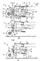
- Figures 3 to 6 show this process of transforming the machine (1) to bring it from the working position into the transport position.
- the first phase is shown in Figure 3. It consists of lifting the body (3) of the machine (1) to bring it into a high position. To do this, oil is injected into the hydraulic cylinders (31) through the lines (37) so that they lengthen. Elongating, they produce the rotation of the suspension arms (20) in the yokes (19). As the working wheels (17) remain in contact with the ground (32), this rotation of the suspension arms (20) in the yokes (19) causes the body (3) to move away from the ground (32).
- the transport wheels (27) rotate, during transport, in planes of rotation substantially parallel to the longitudinal axis (39) of the body (3) of the machine (1) (see FIG. 1).
- the center of gravity (G) of the body (3) is relatively close to the ground (32).
- the transport wheels (27) being located substantially on either side of the body (3) of the machine (1, they are loaded relatively uniformly. All of these provisions increase the stability of the machine (1) during transport .
- the front (5) of the drawbar (4) can remain coupled to the tractor (2).
- the relative pivoting between the drawbar (4) and the body (3) of the machine (1) causes the rotation of the body (3) of the machine (1) around the axis (12). This is possible because the body (3) of the machine (1) is supported on the ground (32) by means of the transport wheels (27), and can therefore roll on the ground (32).
- the additional connection to the transport between the drawbar (4) and the body (3) of the machine (1) takes place automatically. It will also be noted that when putting into the working position from the transport position, the drawbar (4) can also, thanks to the yoke (46), automatically untie from the additional connecting means (42).
- the transport wheels (27) are brought manually to the lowered transport position or to the raised position of rest by the operator, in the embodiment of FIGS. 9 and 10, this phase is carried out using extensible and retractable means, such as the hydraulic cylinder (49).
- This hydraulic cylinder (49) acts between the arms (25) which for this purpose have two arm extensions (50).
- the transport wheels (27) are in the raised rest position.
- the line (51) of the hydraulic cylinder (49) is under pressure, which tends to want to shorten the length of the cylinder (49) which then presses the arms (25) supporting the transport wheels (27) against the high stops ( 35) and maintains said wheels (27) in this position.
Landscapes
- Life Sciences & Earth Sciences (AREA)
- Environmental Sciences (AREA)
- Engineering & Computer Science (AREA)
- Mechanical Engineering (AREA)
- Soil Sciences (AREA)
- Agricultural Machines (AREA)
Applications Claiming Priority (2)
| Application Number | Priority Date | Filing Date | Title |
|---|---|---|---|
| FR8411626 | 1984-07-19 | ||
| FR8411626A FR2567710B1 (fr) | 1984-07-19 | 1984-07-19 | Procede de transformation d'une machine de recolte pour l'amener d'une position de travail dans une position de transport, et machine de recolte utilisant ce procede |
Publications (3)
| Publication Number | Publication Date |
|---|---|
| EP0178239A1 EP0178239A1 (fr) | 1986-04-16 |
| EP0178239B1 EP0178239B1 (fr) | 1990-04-18 |
| EP0178239B2 true EP0178239B2 (fr) | 1993-04-21 |
Family
ID=9306376
Family Applications (1)
| Application Number | Title | Priority Date | Filing Date |
|---|---|---|---|
| EP85440050A Expired - Lifetime EP0178239B2 (fr) | 1984-07-19 | 1985-07-15 | Procédé de transformation d'une machine de récolte pour l'amener d'une position de travail dans une position de transport, et machine de récolte utilisant ce procédé |
Country Status (8)
| Country | Link |
|---|---|
| US (1) | US4986064A (da) |
| EP (1) | EP0178239B2 (da) |
| AU (1) | AU580786B2 (da) |
| DE (1) | DE3577175D1 (da) |
| DK (1) | DK172265B1 (da) |
| FR (1) | FR2567710B1 (da) |
| HU (1) | HU206008B (da) |
| ZA (1) | ZA855265B (da) |
Families Citing this family (54)
| Publication number | Priority date | Publication date | Assignee | Title |
|---|---|---|---|---|
| FR2608358B1 (fr) * | 1986-12-22 | 1991-05-17 | Kuhn Sa | Machine agricole |
| AU629268B2 (en) * | 1988-12-01 | 1992-10-01 | Alistair Edmond Stanley Gleeson | Mowers |
| FR2660518B1 (fr) * | 1990-04-05 | 1993-06-11 | Kuhn Sa | Machine agricole avec dispositif de detection de la position intermediaire du moyen de liaison. |
| DE4108449A1 (de) * | 1991-03-15 | 1992-09-17 | Krone Bernhard Gmbh Maschf | Maehmaschine |
| US5272859A (en) * | 1992-04-14 | 1993-12-28 | Hay & Forage Industries | Mechanical drive center pivot mower conditioner |
| FR2696898B1 (fr) * | 1992-10-16 | 1994-12-09 | Kuhn Sa | Faucheuse avec un entraînement perfectionné des rouleaux de traitement. |
| US5463852A (en) | 1994-04-28 | 1995-11-07 | Hay & Forage Industries | Wide cut harvester having rotary cutter bed |
| US5433064A (en) | 1994-04-28 | 1995-07-18 | Hay & Forage Industries | Rotary cutter bed harvester with non-auger conveying means for outboard cutters |
| FR2724689B1 (fr) * | 1994-09-16 | 1997-01-24 | Kuhn Sa | Mecanisme de verrouillage destine a equiper principalement une machine agricole |
| FR2736505B1 (fr) * | 1995-07-13 | 1997-09-26 | Kuhn Sa | Faucheuse avec un dispositif d'andainage perfectionne |
| FR2743978B1 (fr) * | 1996-01-31 | 1998-04-17 | Kuhn Sa | Faucheuse avec organe de depose perfectionne |
| US6003291A (en) * | 1996-04-09 | 1999-12-21 | Kuhn, S.A. | Agriculture machine |
| FR2751166B1 (fr) * | 1996-07-22 | 1998-09-18 | Kuhn Sa | Machine agricole de recolte de vegetaux avec deux unites de conditionnement |
| US6857254B2 (en) * | 1996-07-27 | 2005-02-22 | Ferris Industries, Inc. | Mower suspension system and method |
| DK173601B1 (da) * | 1996-08-15 | 2001-04-23 | Freudendahl J Fab As | Slåmaskine med arbejdshjul og transporthjul |
| FR2759531B1 (fr) * | 1997-02-14 | 1999-04-23 | Kuhn Sa | Machine agricole de coupe comportant un dispositif de suspension perfectionne du mecanisme de coupe |
| FR2759533B1 (fr) * | 1997-02-14 | 1999-04-23 | Kuhn Sa | Faucheuse comportant un dispositif empechant la transmission de tout ou partie des vibrations entre le mecanisme de coupe et la structure porteuse |
| FR2784003B1 (fr) | 1998-10-02 | 2000-12-29 | Kuhn Sa | Machine agricole comportant un timon pivotable et des organes de transmission comprenant un accouplement a joints universels |
| US6199355B1 (en) * | 1998-03-09 | 2001-03-13 | New Holland North America, Inc. | Control apparatus for rotatable gearbox on crop harvester |
| US6044633A (en) * | 1998-03-09 | 2000-04-04 | New Holland North America, Inc. | Control apparatus for rotatable gearbox on crop harvester |
| US6082085A (en) * | 1998-05-13 | 2000-07-04 | Agco Corporation | Foliage mowing implement having mechanical drive with main gearbox rotation |
| US6178730B1 (en) | 1998-05-22 | 2001-01-30 | Thomas R. Visser | Single shaker head harvesting apparatus and method |
| US5970695A (en) * | 1998-08-21 | 1999-10-26 | Mac Don Industries Ltd. | Self contained transport for crop harvesting header |
| US6213034B1 (en) | 1998-08-27 | 2001-04-10 | Case Corporation | Planter apparatus and method |
| US6158201A (en) | 1998-09-15 | 2000-12-12 | Hay & Forage Industries | Rotary mower conditioner having improved cut crop flow |
| FR2786977B1 (fr) | 1998-12-14 | 2001-02-16 | Kuhn Sa | Faucheuse comportant un dispositif centralise de reglage de la force d'allegement exercee sur le mecanisme de recolte |
| FR2774853B1 (fr) | 1999-02-15 | 2001-02-16 | Kuhn Sa | Organe de coupe pour une machine de coupe notamment une faucheuse |
| FR2791224B1 (fr) | 1999-03-24 | 2001-05-25 | Kuhn Sa | Dispositif de coupe d'une machine de coupe, par exemple faucheuse comportant un dispositif d'entrainement du produit coupe |
| FR2792164B1 (fr) | 1999-04-16 | 2001-05-25 | Kuhn Sa | Dispositif de traitement de fourrage coupe et faucheuse utilisant un tel dispositif de traitement |
| FR2792161B1 (fr) | 1999-04-16 | 2001-05-25 | Kuhn Sa | Machine de coupe comportant un dispositif de coupe lie a un chassis au moyen d'un dispositif de liaison ameliore |
| FR2793379B1 (fr) | 1999-05-11 | 2001-07-06 | Kuhn Sa | Dispositif d'adaptation pour barre d'attelage de tracteur |
| FR2794206B1 (fr) | 1999-05-26 | 2001-07-06 | Kuhn Sa | Procede de montage/demontage et de reglage automatique de la tension d'un organe de transmission sans fin - machine agricole utilisant un tel procede |
| DK174023B1 (da) * | 1999-09-24 | 2002-04-29 | Freudendahl J Fab As | Bugseret slåmaskine |
| US6238170B1 (en) | 2000-07-12 | 2001-05-29 | Agco Corporation | Agricultural implement trailer |
| CA2369907A1 (en) * | 2002-01-25 | 2003-07-25 | Stanley J. Boyko | Variable offset rotary mower |
| US7726108B1 (en) | 2009-01-14 | 2010-06-01 | Agco Corporation | Wide cut rotary harvester having cut crop feeder mechanism |
| BE1018757A3 (nl) * | 2009-05-15 | 2011-08-02 | Cnh Belgium Nv | Een oogstmachine met een bevestigingsinrichting voor een steunwiel en een methode voor het opbergen van een steunwiel van een oogstmachine. |
| AU2010241204A1 (en) | 2009-11-04 | 2011-05-19 | Renn Mill Center Inc. | Towed vehicle having two towing modes |
| US7926249B1 (en) | 2009-11-17 | 2011-04-19 | Cnh America Llc | Transport system for a harvest header |
| US8333249B1 (en) * | 2011-03-24 | 2012-12-18 | Minton Herman E | Portable field roller device |
| US9185838B2 (en) * | 2012-04-26 | 2015-11-17 | Macdon Industries Ltd. | Crop machine with operation of two hydraulic machine elements based on movement of one machine part relative to another |
| US9622404B2 (en) | 2013-09-11 | 2017-04-18 | Cnh Industrial America Llc | Integral lateral transport of a mower |
| US9596808B2 (en) | 2014-04-30 | 2017-03-21 | Cnh Industrial America Llc | Transport system for a center pivot agricultural machine |
| US9386748B2 (en) * | 2014-05-02 | 2016-07-12 | Cnh Industrial America Llc | Transport system for a header of an agricultural harvester |
| US9603306B2 (en) * | 2014-07-09 | 2017-03-28 | Cnh Industrial America Llc | Agricultural machine with retaining elements for retaining a header in an elevated position |
| US9565800B2 (en) | 2014-09-08 | 2017-02-14 | Cnh Industrial America Llc | Windrow shield control system for a header of an agricultural harvester |
| BE1024333B1 (nl) * | 2016-06-23 | 2018-02-01 | Cnh Industrial Belgium Nv | Maaibordsteun voor een oogstmachine |
| US10779473B2 (en) * | 2018-04-18 | 2020-09-22 | Cnh Industrial America Llc | Harvester header support |
| EP3669624B1 (en) * | 2018-12-17 | 2023-09-20 | CNH Industrial Belgium NV | A combine header equipped with an automated header transport system and header steering mechanism |
| EP3669625B1 (en) * | 2018-12-17 | 2023-08-16 | CNH Industrial Belgium NV | A combine header equipped with an automated header transport system and drawbar |
| EP3669626B1 (en) * | 2018-12-17 | 2021-08-18 | CNH Industrial Belgium NV | A combine header equipped with an automated header transport system |
| US11690316B2 (en) * | 2020-03-26 | 2023-07-04 | Cnh Industrial America Llc | Deployment mechanism and hydraulic system for an agricultural mower |
| US11547034B2 (en) * | 2020-03-26 | 2023-01-10 | Cnh Industrial America Llc | Lateral transport system for an agricultural mower |
| US11497168B2 (en) * | 2020-03-26 | 2022-11-15 | Cnh Industrial America Llc | Lateral transport system for an agricultural mower with non-parallel axes of transport deployment and wheel rotation |
Family Cites Families (31)
| Publication number | Priority date | Publication date | Assignee | Title |
|---|---|---|---|---|
| US576406A (en) * | 1897-02-02 | Pole connection for harvesters | ||
| US335950A (en) * | 1886-02-09 | osbobne | ||
| US2833105A (en) * | 1955-05-31 | 1958-05-06 | Case Co J I | Transport truck for windrowers |
| US2806707A (en) * | 1955-06-01 | 1957-09-17 | Int Harvester Co | Quick detachable transport wheels for windrow harvesters |
| US3142144A (en) * | 1961-07-03 | 1964-07-28 | Archer Daniels Midland Co | Roadable wide working-width machine |
| FR1524150A (fr) * | 1967-02-13 | 1968-05-10 | Kuhn Freres & Cie | Faucheuse à disques |
| FR1562887A (da) * | 1967-12-22 | 1969-04-11 | ||
| FR1562886A (da) * | 1967-12-22 | 1969-04-11 | ||
| FR2033517A5 (da) * | 1969-02-25 | 1970-12-04 | Kuhn Freres & Cie | |
| US3635495A (en) * | 1969-11-28 | 1972-01-18 | Int Harvester Co | Telescoping implement tongue |
| US3721461A (en) * | 1971-08-27 | 1973-03-20 | Deere & Co | Apparatus and method for converting an implement between operating and transport positions |
| FR2228417B1 (da) * | 1973-05-07 | 1975-08-22 | Kuhn Sa | |
| US4034623A (en) * | 1974-02-13 | 1977-07-12 | Ideal Industries, Inc. | Folding mechanism for hinged implement frame extensions |
| US3962853A (en) * | 1974-03-29 | 1976-06-15 | Sperry Rand Corporation | Method of converting an implement frame from a forward harvesting mode to a lateral transport mode |
| US3919831A (en) * | 1975-01-24 | 1975-11-18 | Sperry Rand Corp | Crop harvesting machine convertible between field operating and road transporting orientations |
| FR2342017A1 (fr) * | 1976-02-25 | 1977-09-23 | Kuhn Sa | Machine agricole du type faucheuse ou faucheuse-conditionneuse a caisson pivotant |
| FR2358819A1 (fr) * | 1976-07-20 | 1978-02-17 | Kuhn Sa | Deflecteur avant pour faucheuse a disques entraines par le bas |
| AU514873B2 (en) * | 1976-10-29 | 1981-03-05 | Fuss, Albert Keith | Transport apparatus for articulated agricultural implement |
| FR2397780A1 (fr) * | 1977-07-22 | 1979-02-16 | Kuhn Sa | Faucheuse-conditionneuse perfectionnee |
| FR2419006A1 (fr) * | 1978-03-10 | 1979-10-05 | Kuhn Sa | Dispositif reducteur de la largeur des andains formes par les faucheuses |
| FR2428384A1 (fr) * | 1978-06-13 | 1980-01-11 | Kuhn Sa | Faucheuse-conditionneuse combinee |
| FR2456461A1 (fr) * | 1979-05-16 | 1980-12-12 | Kuhn Sa | Faucheuse rotative a barres de coupe jumelees |
| FR2458981A1 (fr) * | 1979-06-19 | 1981-01-09 | Kuhn Sa | Bati de machine agricole |
| FR2474811A1 (fr) * | 1980-02-04 | 1981-08-07 | Kuhn Sa | Barre de coupe perfectionnee |
| US4340239A (en) * | 1980-05-05 | 1982-07-20 | Shoup Kenneth E | Farm implement with two-way hitch |
| GB2079573B (en) * | 1980-07-08 | 1983-09-01 | Massey Ferguson Services Nv | Crop harvesters |
| FR2496394A1 (fr) * | 1980-12-18 | 1982-06-25 | Kuhn Sa | Perfectionnement aux supports d'elements coupants des faucheuses rotatives |
| FR2496391A1 (fr) * | 1980-12-19 | 1982-06-25 | Kuhn Sa | Perfectionnement aux faucheuses |
| FR2502888A1 (fr) * | 1981-04-02 | 1982-10-08 | Kuhn Sa | Barre de coupe a protecteur de disque lateral amovible |
| FR2520970B1 (fr) * | 1982-02-08 | 1987-01-30 | Kuhn Sa | Faucheuse rotative avec arbre de transmission perfectionne et procede de realisation de cet arbre |
| US4442662A (en) * | 1982-09-30 | 1984-04-17 | Sperry Corporation | Method and apparatus for converting a harvesting machine between operating and transport positions |
-
1984
- 1984-07-19 FR FR8411626A patent/FR2567710B1/fr not_active Expired
-
1985
- 1985-07-10 AU AU44768/85A patent/AU580786B2/en not_active Ceased
- 1985-07-12 ZA ZA855265A patent/ZA855265B/xx unknown
- 1985-07-15 DE DE8585440050T patent/DE3577175D1/de not_active Expired - Lifetime
- 1985-07-15 EP EP85440050A patent/EP0178239B2/fr not_active Expired - Lifetime
- 1985-07-16 HU HU852732A patent/HU206008B/hu not_active IP Right Cessation
- 1985-07-19 DK DK331485A patent/DK172265B1/da not_active IP Right Cessation
-
1988
- 1988-11-07 US US07/270,455 patent/US4986064A/en not_active Expired - Lifetime
Also Published As
| Publication number | Publication date |
|---|---|
| EP0178239A1 (fr) | 1986-04-16 |
| AU580786B2 (en) | 1989-02-02 |
| HUT39046A (en) | 1986-08-28 |
| FR2567710B1 (fr) | 1987-05-07 |
| ZA855265B (en) | 1986-03-26 |
| DE3577175D1 (de) | 1990-05-23 |
| AU4476885A (en) | 1986-01-23 |
| HU206008B (en) | 1992-08-28 |
| DK331485A (da) | 1986-01-20 |
| US4986064A (en) | 1991-01-22 |
| DK172265B1 (da) | 1998-02-16 |
| EP0178239B1 (fr) | 1990-04-18 |
| DK331485D0 (da) | 1985-07-19 |
| FR2567710A1 (fr) | 1986-01-24 |
Similar Documents
| Publication | Publication Date | Title |
|---|---|---|
| EP0178239B2 (fr) | Procédé de transformation d'une machine de récolte pour l'amener d'une position de travail dans une position de transport, et machine de récolte utilisant ce procédé | |
| EP0356358B1 (fr) | Faucheuse à châssis perfectionné | |
| EP0486414B1 (fr) | Machine agricole s'adaptant aisément au relief du terrain et comportant un carter pivotant | |
| EP0454602B1 (fr) | Machine de fenaison avec plusieurs rotors | |
| FR2654893A1 (fr) | Machine agricole avec dispositif de suspension du groupe d'organes de travail perfectionne. | |
| FR2660518A1 (fr) | Machine agricole avec dispositif de detection de la position intermediaire du moyen de liaison. | |
| EP0511922B1 (fr) | Machine de coupe perfectionnée avec structure d'attelage pivotante | |
| FR2601547A1 (fr) | Appareil de pulverisation pour agriculture. | |
| EP1496734B1 (fr) | Machine de fenaison | |
| WO2012143641A1 (fr) | Machine agricole avec un dispositif de repliage perfectionne | |
| FR2746576A1 (fr) | Machine agricole du genre faneuse a rateaux rotatifs multiples, convertible d'une position de travail deployee a une position de transport ramassee | |
| EP1076482B1 (fr) | Machine de fenaison avec au moins un rotor d'andainage muni d'un deflecteur dont la position est reglable | |
| EP0310532B2 (fr) | Machine de fenaison avec un dispositif de protection perfectionné | |
| EP0426588B1 (fr) | Perfectionnement aux machines agricoles destinées notamment à la fenaison | |
| FR2705861A1 (fr) | Machine de fenaison avec un dispositif de transport déplaçable. | |
| EP0804871B1 (fr) | Machine de coupe | |
| EP1111986B1 (fr) | Dispositif de roulement pour engin agricole | |
| FR2693345A1 (fr) | Faucheuse destinée à être liée à un véhicule moteur et comportant un dispositif de dépose perfectionné. | |
| EP0486415B1 (fr) | Faucheuse à châssis indépendant comportant un dispositif de suspension et un dispositif d'allègement perfectionnés | |
| FR2490165A1 (fr) | Dispositif de chargement pour vehicules, en particulier pour ambulances et vehicules, ainsi equipes | |
| EP2959759A1 (fr) | Machine agricole munie d'un dispositif de centrage | |
| FR2662650A1 (fr) | Ensemble de ramassage de legumes. | |
| FR2543905A1 (fr) | Tracteur ou vehicule dont les roues directrices sont egalement motrices | |
| FR2699044A1 (fr) | Machine de fenaison avec des roues de transport déplaçables en hauteur. | |
| FR2549687A1 (fr) | Faneuse avec organes porteurs et arbres d'entrainement repliables |
Legal Events
| Date | Code | Title | Description |
|---|---|---|---|
| PUAI | Public reference made under article 153(3) epc to a published international application that has entered the european phase |
Free format text: ORIGINAL CODE: 0009012 |
|
| AK | Designated contracting states |
Kind code of ref document: A1 Designated state(s): DE GB IT NL SE |
|
| 17P | Request for examination filed |
Effective date: 19860922 |
|
| 17Q | First examination report despatched |
Effective date: 19880104 |
|
| GRAA | (expected) grant |
Free format text: ORIGINAL CODE: 0009210 |
|
| AK | Designated contracting states |
Kind code of ref document: B1 Designated state(s): DE GB IT NL SE |
|
| REF | Corresponds to: |
Ref document number: 3577175 Country of ref document: DE Date of ref document: 19900523 |
|
| ITF | It: translation for a ep patent filed |
Owner name: BARZANO' E ZANARDO MILANO S.P.A. |
|
| GBT | Gb: translation of ep patent filed (gb section 77(6)(a)/1977) | ||
| PLBI | Opposition filed |
Free format text: ORIGINAL CODE: 0009260 |
|
| 26 | Opposition filed |
Opponent name: VICON B.V. Effective date: 19910116 |
|
| NLR1 | Nl: opposition has been filed with the epo |
Opponent name: VICON B.V. |
|
| ITTA | It: last paid annual fee | ||
| PUAH | Patent maintained in amended form |
Free format text: ORIGINAL CODE: 0009272 |
|
| STAA | Information on the status of an ep patent application or granted ep patent |
Free format text: STATUS: PATENT MAINTAINED AS AMENDED |
|
| 27A | Patent maintained in amended form |
Effective date: 19930421 |
|
| AK | Designated contracting states |
Kind code of ref document: B2 Designated state(s): DE GB IT NL SE |
|
| ITF | It: translation for a ep patent filed |
Owner name: BARZANO' E ZANARDO MILANO S.P.A. |
|
| GBTA | Gb: translation of amended ep patent filed (gb section 77(6)(b)/1977) |
Effective date: 19930414 |
|
| NLR2 | Nl: decision of opposition | ||
| PGFP | Annual fee paid to national office [announced via postgrant information from national office to epo] |
Ref country code: SE Payment date: 19930727 Year of fee payment: 9 |
|
| NLR3 | Nl: receipt of modified translations in the netherlands language after an opposition procedure | ||
| PG25 | Lapsed in a contracting state [announced via postgrant information from national office to epo] |
Ref country code: SE Effective date: 19940716 |
|
| EUG | Se: european patent has lapsed |
Ref document number: 85440050.4 Effective date: 19950210 |
|
| EUG | Se: european patent has lapsed |
Ref document number: 85440050.4 |
|
| REG | Reference to a national code |
Ref country code: GB Ref legal event code: IF02 |
|
| PGFP | Annual fee paid to national office [announced via postgrant information from national office to epo] |
Ref country code: GB Payment date: 20030630 Year of fee payment: 19 |
|
| PGFP | Annual fee paid to national office [announced via postgrant information from national office to epo] |
Ref country code: NL Payment date: 20040623 Year of fee payment: 20 |
|
| PGFP | Annual fee paid to national office [announced via postgrant information from national office to epo] |
Ref country code: DE Payment date: 20040629 Year of fee payment: 20 |
|
| PG25 | Lapsed in a contracting state [announced via postgrant information from national office to epo] |
Ref country code: GB Free format text: LAPSE BECAUSE OF NON-PAYMENT OF DUE FEES Effective date: 20040715 |
|
| GBPC | Gb: european patent ceased through non-payment of renewal fee |
Effective date: 20040715 |
|
| PG25 | Lapsed in a contracting state [announced via postgrant information from national office to epo] |
Ref country code: NL Free format text: LAPSE BECAUSE OF EXPIRATION OF PROTECTION Effective date: 20050715 |
|
| NLV7 | Nl: ceased due to reaching the maximum lifetime of a patent |
Effective date: 20050715 |