EP0175829B1 - Bandage pneumatique - Google Patents
Bandage pneumatique Download PDFInfo
- Publication number
- EP0175829B1 EP0175829B1 EP19840630122 EP84630122A EP0175829B1 EP 0175829 B1 EP0175829 B1 EP 0175829B1 EP 19840630122 EP19840630122 EP 19840630122 EP 84630122 A EP84630122 A EP 84630122A EP 0175829 B1 EP0175829 B1 EP 0175829B1
- Authority
- EP
- European Patent Office
- Prior art keywords
- grooves
- tire
- plane
- width
- circumferential
- Prior art date
- Legal status (The legal status is an assumption and is not a legal conclusion. Google has not performed a legal analysis and makes no representation as to the accuracy of the status listed.)
- Expired
Links
Images


Classifications
-
- B—PERFORMING OPERATIONS; TRANSPORTING
- B60—VEHICLES IN GENERAL
- B60C—VEHICLE TYRES; TYRE INFLATION; TYRE CHANGING; CONNECTING VALVES TO INFLATABLE ELASTIC BODIES IN GENERAL; DEVICES OR ARRANGEMENTS RELATED TO TYRES
- B60C11/00—Tyre tread bands; Tread patterns; Anti-skid inserts
- B60C11/03—Tread patterns
- B60C11/0306—Patterns comprising block rows or discontinuous ribs
-
- B—PERFORMING OPERATIONS; TRANSPORTING
- B60—VEHICLES IN GENERAL
- B60C—VEHICLE TYRES; TYRE INFLATION; TYRE CHANGING; CONNECTING VALVES TO INFLATABLE ELASTIC BODIES IN GENERAL; DEVICES OR ARRANGEMENTS RELATED TO TYRES
- B60C11/00—Tyre tread bands; Tread patterns; Anti-skid inserts
- B60C11/03—Tread patterns
- B60C11/0302—Tread patterns directional pattern, i.e. with main rolling direction
-
- B—PERFORMING OPERATIONS; TRANSPORTING
- B60—VEHICLES IN GENERAL
- B60C—VEHICLE TYRES; TYRE INFLATION; TYRE CHANGING; CONNECTING VALVES TO INFLATABLE ELASTIC BODIES IN GENERAL; DEVICES OR ARRANGEMENTS RELATED TO TYRES
- B60C11/00—Tyre tread bands; Tread patterns; Anti-skid inserts
- B60C11/03—Tread patterns
- B60C2011/0337—Tread patterns characterised by particular design features of the pattern
- B60C2011/0386—Continuous ribs
- B60C2011/0388—Continuous ribs provided at the equatorial plane
Definitions
- This invention relates to pneumatic tires for passenger cars of the type described in the preamble to claim 1.
- GB-A-1 237 616 for example, describes such tires.
- High performance tires typically have ground contacting tread portions divided into a plurality of circumferentially spaced lands or ribs by circumferentially continuous straight grooves. These lands may be further divided into circumferentially spaced blocks.
- a problem associated with high speed tires is that the mid-circumferential portion of the tread portion sometimes wears more rapidly than the remainder of the tread portion.
- grooved road surfaces that is road surfaces with grooves extending along the length of the road. These grooves are typically between 2-2.5 cm apart.
- One area where such road surfaces are common is in California.
- vehicles mounted on rib type tires are driven on such road surfaces there may be some interaction between the tire and the grooved road surface that produces a feeling of unease in the driver. This interaction is sometimes known as wander, and more particularly California wander.
- the width of the central rib on each side of the mid-circumferential plane is about 4%-10% of the tread width, and the lands on each side of said plane have widths that increase in steps as the lands are progressively located axially outwardly from the the mid-circumferential plane, such that each land is at least approximately one and one half times as wide as its axially inward adjacent land.
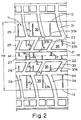
- FIG. 1 and 2 there is illustrated a pneumatic tire 10 for a passenger car, and which has a radial carcass construction.
- the tire 10 has a ground contacting tread portion 11 with a pair of lateral edges 12 and 13.
- the tread portion 11 is joined at its lateral edges 12 and 13 to a pair of sidewalls 14 that extend radially inwards from the tread portion each terminating in a bead portion 15.
- the tire has a mid-circumferential plane M-M perpendicular to the rotational axis of the tire and located midway between the lateral edges 12 and 13 of the tread.
- the tread portion 11 has four straight grooves 21, 22, 23, and 24 extending circumferentially about the tread and which are symmetrically located, about the mid-circumferential plane M-M.
- the straight grooves 21,22, 23, and 24 divide the tread portion into five axially spaced lands, 25, 26, 27, 28, and 29.
- a central land 27 is located at the mid-circumferential plane M-M and is in the form of a continuous rib, the other axially spaced lands 25, 26, 28, and 29 are each further divided into circumferentially spaced blocks 36 by lateral grooves 31, 32, 33, and 34, respectively.
- the lands 25, 26, 28, and 29 could be in the form of circumferentially continuous ribs.
- the lateral grooves 31 and 32 to one side of the plane M-M are arranged so that the lateral grooves 32 adjacent the rib 27 extend diagonally across the tread portion 11 at an angle of between 55°-65° to the mid-circumferential plane M-M and the grooves 31 extend at an angle in the diagonally opposite direction so that the lateral grooves 31 and 32 form a series of substantially 'V' shaped configurations all pointed in one direction of rotation of the tire.
- the lateral grooves 33 and 34 to the other side of the lateral plane M-M are arranged to form a series of substantially'V' shaped configurations all pointed in the other direction of rotation of the tire.
- the pairs of lateral grooves 31 and 32, and 33 and 34, which form the substantially 'V' shaped configurations to each side of the plane M-M are not directly interconnected at the apex of the 'V' configuration but are circumferentially staggered by a pitch of approximately one half the circumferential length of a block 36.
- the pairs of lateral grooves could be directly interconnected to form a true 'V' shaped configuration.
- the tread portion 11 extends between the two lateral edges 12 and 13 and has a tread width TW.
- the tread width TW is defined as the greatest axial distance across the tire measured from the footprint of the tire when the tire is mounted on a specified rim and is inflated to a design pressure at a rated load.
- the axial widths W 1 , W 2 and W 3 of the lands 27, 28, and 29 respectively, to one side of the plane M-M are equal to the respective widths W 1 , W 2 , and W 3 of the lands 27, 26, and 25 to the other side of the plane M-M.
- the widths W 1 , W 2 , W 3 of the lands increase in stepwise progression axially outwardly from the plane M-M.
- the terms 'axial' and 'axially' refer to displacement along or parallel to the axis of rotation of the tire and the terms 'axially inner' and 'axially outer' refer to positions relative to the mid-circumferential plane M-M.
- the width W 1 of the rib 27 on each side of the plane M-M is approximately 6% of the tread width TW.
- W 2 is approximately equal to 2.4 W 1
- W 3 is equal to approximately 3.7 W 1 , so that the lands progressively almost double in size axially outwardly from the plane M-M, and at least increase in width in steps by a factor of about one and one half.
- the axial widths X 1 and X 2 of the circumferential grooves 22 and 24 on said one side of the plane M-M are equal to the respective widths X 1 and X 2 of the circumferential grooves 21 and 23 on said other side of the plane M-M.
- the widths X 1 and X 2 of the grooves also increase axially outwardly from the plane M-M. In the present example X 2 is approximately equal to 1.7 X 1 .
- the axial widths W 1 , W 2 , and W 3 of the lands increase axially outwardly, the axial widths X 1 and X 2 of the grooves also increase.
- the width X 1 or X 2 of any groove 21, 22, 23, and 24 is related to the width W 1 or W 2 of its adjacent axially inner land, such that the width of any land is between 150%-250% of the width of its adjacent outer groove.
- the width W 1 of the rib 27 is approximately 170% of the width X 1 of its adjacent groove 21 or 22
- the width W 2 of the lands 26 or 28 is 250% of the width X 2 of the adjacent outer grooves 23 or 24 respectively.
- the stiffness of the tread is measured in the footprint of the tire under rated load conditions, and is a beam stiffness measure in the circumferential direction (longitudinal) or axial direction (lateral stiffness).
- the portions of the tread adjacent the edges 11 and 12 have a high lateral stiffness (a factor of 10-15 times higher than the lateral stiffness of the center portion) and a low longitudinal stiffness (1/4 to 1/2 the longitudinal stiffness of the center rib).
- the central rib 27 and the blocks 36 all have blades 37 therein for improving the traction of the tire blades, sometimes known as sipes, are narrow grooves that close in the footprint of a tire.
- the blades 37 all extend axially across the tread, and in the present arrangement the blades 37A in the blocks 36 open into the respective adjacent wide circumferential groove 23 or 24.
- the tire tread portion 111 has a pair of lateral edges 112 and 113 separated by a tread width TW 2 .
- the tread portion 111 has six circumferential straight grooves 119, 120, 121, 122, 123, and 124 that divide the tread portion into seven axially spaced lands 125, 126, 127,128,129,130, and 131.
- the central land 127 is in the form of a continuous rib located at the mid-circumferential plane M-M of the tire, and the other axially spaced lands 125, 126, 128, 129, 130 and 131 are further divided into circumferentially spaced blocks 136 by lateral grooves 141, 142, 143,144,145, and 146 respectively.
- the block 136 and central rib 127 are provided with blades 137.
- the lateral grooves 146, 141 and 142 on one side of the plane M-M are arranged to form continuous lateral grooves in the form of curves and which extend from the center rib 27 axially outwardly to the tread edge 112 in one circumferential direction of the tire, and the lateral grooves 143, 144 and 145 on the other side of the plane M-M make similar continuous lateral grooves to the other edge 113 in the opposite circumferential direction of the tire.
- the axial widths W 1 , W 2 , W 3 and W 4 of the lands 125,126,127,128, 129, 130, and 131 on each side of the plane M-M increase in stepwise progression axially outwardly.
- the width W 1 of rib 127 is approximately 4% of the treadwidth TW 2 .
- W 4 is approximately equal to 4.5 W 1
- W 3 is approximately equal to 2.5 W 1
- W 2 is approximately equal to 1.7W 1 .
- the axial widths X 1 , X 2 , and X 3 of the circumferential grooves 119, 120, 121, 122, 123, and 124 also increase axially outwardly from the plane M-M.
- X 3 is approximately equal to 2.2 X 1 and X 2 is approximately equal to 1.4 X 1 .
- the axial widths W 1 , W 2 , W 3 , and W 4 or the lands increase, the axial widths X 1 , X 2 , and X 3 of the grooves also increase so that the width of any land to one side of the plane M-M is about twice the width of its adjacent outer groove.
- the width W 1 of the rib 127 is approximately 175% of the width of X 1 of the grooves 121, and 122
- the width W 2 of the lands 126 and 128 is approximately 220% of the width X 2 of grooves 123 and 124
- the width W 3 of the lands 125 and 129 is approximately 200% of the width X 3 of the grooves 119, and 120.
- the width 'W' of the any land is approximately twice the width X of its adjacent outer groove.
- the tread portion 211 illustrated is very similar to the tread illustrated in Figure 3.
- the tread portion 211 has a pair of lateral edges 212 and 213 separated by a tread width TW 3 .
- the tread has six grooves 219, 220, 221,222, 223, and 224 dividing the tread up into seven axially spaced lands 225, 226, 227, 228, 229, 230, and 231.
- the central land 227 is in the form of a continuous rib and the other lands 225, 226, 228, 229, 230, and 231 are further subdivided into circumferentially spaced blocks 236 by lateral grooves 241, 242, 243, 244, 245 and 246 respectively.
- lateral grooves 246, 241, and 242 on one side of the plane M-M forming a groove extending from the center rib 227 axially outwardly to the tread edge 212 in one circumferential direction of rotation, and the lateral groove 143, 144, and 145 on the other side of the plane M-M making a continuous groove extending axially outwardly to the other tread edge 213 and also in said one circumferential direction.
- the lateral grooves illustrated in Figure 4 are arcuate, in alternative designs they could be straight.
- the blades could be altered in number and form, and various aspects of the illustrated tread portions could be mixed together in a different manner, such as the tread portion in Figure 3 having only four straight circumferential grooves instead of six grooves, or alternatively the tread portion of Figure 2 having six straight circumferential grooves instead of four.
Claims (10)
Priority Applications (2)
| Application Number | Priority Date | Filing Date | Title |
|---|---|---|---|
| EP19840630122 EP0175829B1 (fr) | 1984-08-28 | 1984-08-28 | Bandage pneumatique |
| DE8484630122T DE3472547D1 (en) | 1984-08-28 | 1984-08-28 | Pneumatic tires |
Applications Claiming Priority (1)
| Application Number | Priority Date | Filing Date | Title |
|---|---|---|---|
| EP19840630122 EP0175829B1 (fr) | 1984-08-28 | 1984-08-28 | Bandage pneumatique |
Publications (2)
| Publication Number | Publication Date |
|---|---|
| EP0175829A1 EP0175829A1 (fr) | 1986-04-02 |
| EP0175829B1 true EP0175829B1 (fr) | 1988-07-06 |
Family
ID=8192967
Family Applications (1)
| Application Number | Title | Priority Date | Filing Date |
|---|---|---|---|
| EP19840630122 Expired EP0175829B1 (fr) | 1984-08-28 | 1984-08-28 | Bandage pneumatique |
Country Status (2)
| Country | Link |
|---|---|
| EP (1) | EP0175829B1 (fr) |
| DE (1) | DE3472547D1 (fr) |
Cited By (2)
| Publication number | Priority date | Publication date | Assignee | Title |
|---|---|---|---|---|
| USD419928S (en) | 1999-02-25 | 2000-02-01 | Bridgestone/Firestone Research, Inc. | Tire tread |
| EP3173254A1 (fr) | 2015-11-27 | 2017-05-31 | Continental Reifen Deutschland GmbH | Pneumatiques de véhicule |
Families Citing this family (8)
| Publication number | Priority date | Publication date | Assignee | Title |
|---|---|---|---|---|
| GB2192842B (en) * | 1986-06-13 | 1991-01-30 | Bridgestone Corp | Pneumatic tire |
| EP0299766B1 (fr) * | 1987-07-15 | 1993-01-20 | Sumitomo Rubber Industries Limited | Pneumatique |
| JP3029636B2 (ja) * | 1990-04-26 | 2000-04-04 | 株式会社ブリヂストン | 空気入りタイヤ |
| JP2971960B2 (ja) * | 1991-01-16 | 1999-11-08 | 住友ゴム工業株式会社 | 空気入りタイヤ |
| DE4108745A1 (de) * | 1991-03-18 | 1992-09-24 | Sp Reifenwerke Gmbh | Luftreifen |
| DE69307473T2 (de) * | 1992-11-13 | 1997-05-15 | Sumitomo Rubber Ind | Radialer Luftreifen |
| JP2966748B2 (ja) * | 1994-03-08 | 1999-10-25 | 住友ゴム工業株式会社 | 空気入りタイヤ |
| JP2021172325A (ja) * | 2020-04-30 | 2021-11-01 | 横浜ゴム株式会社 | タイヤ |
Family Cites Families (6)
| Publication number | Priority date | Publication date | Assignee | Title |
|---|---|---|---|---|
| BE494612A (fr) * | 1949-03-18 | |||
| GB1019776A (en) * | 1961-12-18 | 1966-02-09 | Ciba Ltd | Basic ethers and process for preparing same |
| AT288893B (de) * | 1968-08-30 | 1971-03-25 | Semperit Ag | Laufflächenprofilierung für Luftreifen |
| FR2227965A1 (en) * | 1973-05-04 | 1974-11-29 | Uniroyal | Tyre cover having long life - by eliminating or reducing selective wear in tread side zones |
| DE2441063A1 (de) * | 1974-08-27 | 1976-03-18 | Dunlop Ag | Laufflaechenprofilierung fuer fahrzeugluftreifen |
| CA1104479A (fr) * | 1978-02-14 | 1981-07-07 | Harold D. Fetty | Traduction non-disponible |
-
1984
- 1984-08-28 DE DE8484630122T patent/DE3472547D1/de not_active Expired
- 1984-08-28 EP EP19840630122 patent/EP0175829B1/fr not_active Expired
Cited By (3)
| Publication number | Priority date | Publication date | Assignee | Title |
|---|---|---|---|---|
| USD419928S (en) | 1999-02-25 | 2000-02-01 | Bridgestone/Firestone Research, Inc. | Tire tread |
| EP3173254A1 (fr) | 2015-11-27 | 2017-05-31 | Continental Reifen Deutschland GmbH | Pneumatiques de véhicule |
| DE102015223537A1 (de) | 2015-11-27 | 2017-06-01 | Continental Reifen Deutschland Gmbh | Fahrzeugluftreifen |
Also Published As
| Publication number | Publication date |
|---|---|
| EP0175829A1 (fr) | 1986-04-02 |
| DE3472547D1 (en) | 1988-08-11 |
Similar Documents
| Publication | Publication Date | Title |
|---|---|---|
| EP0172974B1 (fr) | Bandage pneumatique | |
| EP0678402B1 (fr) | Bande de roulement pour pneumatiques | |
| CA1315182C (fr) | Pneumatique | |
| US4667718A (en) | Pneumatic tire tread | |
| US4574856A (en) | Tread for a pneumatic tire | |
| EP0093071B1 (fr) | Bandage pneumatique | |
| AU643905B2 (en) | A tread for a tire | |
| EP0467146B1 (fr) | Enveloppe de pneumatique | |
| US4856571A (en) | Pneumatic tire | |
| US4546808A (en) | Pneumatic tire | |
| EP0175829B1 (fr) | Bandage pneumatique | |
| US4779656A (en) | Pneumatic tire | |
| US4632166A (en) | Pneumatic tires | |
| US4641695A (en) | Tread for a pneumatic tire | |
| EP0135467B1 (fr) | Bandage pneumatique | |
| GB2170153A (en) | Pneumatic radial tire tread | |
| EP3670209B1 (fr) | Bande de roulement pour pneu de véhicule | |
| EP3666551B1 (fr) | Bande de roulement de pneumatique | |
| EP0148105B1 (fr) | Bandages pneumatiques | |
| EP3970993B1 (fr) | Bande de roulement de pneu et pneu comprenant une structure de stabilisateur | |
| EP4091841B1 (fr) | Pneu doté d'une bande de roulement comportant des lamelles | |
| JPH0419203A (ja) | 高速走行に適した空気入りラジアルタイヤ | |
| AU648681B2 (en) | An asymmetric tread for a high performance low aspect ratio radial tire | |
| CA1234342A (fr) | Semelle pour pneu | |
| CN117460630A (zh) | 用于商用车辆车轮的轮胎 |
Legal Events
| Date | Code | Title | Description |
|---|---|---|---|
| PUAI | Public reference made under article 153(3) epc to a published international application that has entered the european phase |
Free format text: ORIGINAL CODE: 0009012 |
|
| 17P | Request for examination filed |
Effective date: 19840917 |
|
| AK | Designated contracting states |
Kind code of ref document: A1 Designated state(s): AT BE CH DE FR GB IT LI LU NL SE |
|
| RBV | Designated contracting states (corrected) |
Designated state(s): DE |
|
| 17Q | First examination report despatched |
Effective date: 19870720 |
|
| GRAA | (expected) grant |
Free format text: ORIGINAL CODE: 0009210 |
|
| AK | Designated contracting states |
Kind code of ref document: B1 Designated state(s): DE |
|
| REF | Corresponds to: |
Ref document number: 3472547 Country of ref document: DE Date of ref document: 19880811 |
|
| PLBE | No opposition filed within time limit |
Free format text: ORIGINAL CODE: 0009261 |
|
| STAA | Information on the status of an ep patent application or granted ep patent |
Free format text: STATUS: NO OPPOSITION FILED WITHIN TIME LIMIT |
|
| 26N | No opposition filed | ||
| PG25 | Lapsed in a contracting state [announced via postgrant information from national office to epo] |
Ref country code: DE Effective date: 19900501 |