EP0175829B1 - Pneumatic tires - Google Patents
Pneumatic tires Download PDFInfo
- Publication number
- EP0175829B1 EP0175829B1 EP19840630122 EP84630122A EP0175829B1 EP 0175829 B1 EP0175829 B1 EP 0175829B1 EP 19840630122 EP19840630122 EP 19840630122 EP 84630122 A EP84630122 A EP 84630122A EP 0175829 B1 EP0175829 B1 EP 0175829B1
- Authority
- EP
- European Patent Office
- Prior art keywords
- grooves
- tire
- plane
- width
- circumferential
- Prior art date
- Legal status (The legal status is an assumption and is not a legal conclusion. Google has not performed a legal analysis and makes no representation as to the accuracy of the status listed.)
- Expired
Links
Images


Classifications
-
- B—PERFORMING OPERATIONS; TRANSPORTING
- B60—VEHICLES IN GENERAL
- B60C—VEHICLE TYRES; TYRE INFLATION; TYRE CHANGING; CONNECTING VALVES TO INFLATABLE ELASTIC BODIES IN GENERAL; DEVICES OR ARRANGEMENTS RELATED TO TYRES
- B60C11/00—Tyre tread bands; Tread patterns; Anti-skid inserts
- B60C11/03—Tread patterns
- B60C11/0306—Patterns comprising block rows or discontinuous ribs
-
- B—PERFORMING OPERATIONS; TRANSPORTING
- B60—VEHICLES IN GENERAL
- B60C—VEHICLE TYRES; TYRE INFLATION; TYRE CHANGING; CONNECTING VALVES TO INFLATABLE ELASTIC BODIES IN GENERAL; DEVICES OR ARRANGEMENTS RELATED TO TYRES
- B60C11/00—Tyre tread bands; Tread patterns; Anti-skid inserts
- B60C11/03—Tread patterns
- B60C11/0302—Tread patterns directional pattern, i.e. with main rolling direction
-
- B—PERFORMING OPERATIONS; TRANSPORTING
- B60—VEHICLES IN GENERAL
- B60C—VEHICLE TYRES; TYRE INFLATION; TYRE CHANGING; CONNECTING VALVES TO INFLATABLE ELASTIC BODIES IN GENERAL; DEVICES OR ARRANGEMENTS RELATED TO TYRES
- B60C11/00—Tyre tread bands; Tread patterns; Anti-skid inserts
- B60C11/03—Tread patterns
- B60C2011/0337—Tread patterns characterised by particular design features of the pattern
- B60C2011/0386—Continuous ribs
- B60C2011/0388—Continuous ribs provided at the equatorial plane
Description
- This invention relates to pneumatic tires for passenger cars of the type described in the preamble to claim 1. GB-A-1 237 616, for example, describes such tires.
- High performance tires typically have ground contacting tread portions divided into a plurality of circumferentially spaced lands or ribs by circumferentially continuous straight grooves. These lands may be further divided into circumferentially spaced blocks.
- A problem associated with high speed tires is that the mid-circumferential portion of the tread portion sometimes wears more rapidly than the remainder of the tread portion.
- Also, in some areas of the world there are grooved road surfaces, that is road surfaces with grooves extending along the length of the road. These grooves are typically between 2-2.5 cm apart. One area where such road surfaces are common is in California. When vehicles mounted on rib type tires are driven on such road surfaces there may be some interaction between the tire and the grooved road surface that produces a feeling of unease in the driver. This interaction is sometimes known as wander, and more particularly California wander.
- The tire of the present invention attempts to overcome the above described problems through the means recited in the claims.
- Preferably the width of the central rib on each side of the mid-circumferential plane is about 4%-10% of the tread width, and the lands on each side of said plane have widths that increase in steps as the lands are progressively located axially outwardly from the the mid-circumferential plane, such that each land is at least approximately one and one half times as wide as its axially inward adjacent land.
- The invention will be described by way of example and with reference to the accompanying drawings in which:
- Figure 1 is a perspective view of a tire according to the invention;
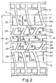
- Figure 2 is a fragmentary enlarged plan view of the tire shown in Figure 1;
- Figure 3 is a fragmentary enlarged plan view of a second tire also according to this invention; and
- Figure 4 is a fragmentary enlarged plan view of a third tire also according to this invention.
- With reference to Figures 1 and 2 there is illustrated a
pneumatic tire 10 for a passenger car, and which has a radial carcass construction. Thetire 10 has a ground contactingtread portion 11 with a pair oflateral edges tread portion 11 is joined at itslateral edges sidewalls 14 that extend radially inwards from the tread portion each terminating in abead portion 15. - The tire has a mid-circumferential plane M-M perpendicular to the rotational axis of the tire and located midway between the
lateral edges tread portion 11 has fourstraight grooves straight grooves central land 27 is located at the mid-circumferential plane M-M and is in the form of a continuous rib, the other axially spacedlands blocks 36 bylateral grooves lands - The
lateral grooves lateral grooves 32 adjacent therib 27 extend diagonally across thetread portion 11 at an angle of between 55°-65° to the mid-circumferential plane M-M and thegrooves 31 extend at an angle in the diagonally opposite direction so that thelateral grooves lateral grooves lateral grooves block 36. In alternative designs it is envisaged that the pairs of lateral grooves could be directly interconnected to form a true 'V' shaped configuration. - The
tread portion 11 extends between the twolateral edges lands lands rib 27 on each side of the plane M-M is approximately 6% of the tread width TW. W2 is approximately equal to 2.4 W1, and W3 is equal to approximately 3.7 W1, so that the lands progressively almost double in size axially outwardly from the plane M-M, and at least increase in width in steps by a factor of about one and one half. - The axial widths X1 and X2 of the
circumferential grooves circumferential grooves - Thus it can be seen that as the axial widths W1, W2, and W3 of the lands increase axially outwardly, the axial widths X1 and X2 of the grooves also increase. The width X1 or X2 of any
groove rib 27 is approximately 170% of the width X1 of itsadjacent groove lands outer grooves - The overall tread pattern as described having the
center rib 27 with the lands and grooves increasing in width radially outwardly gives a tire tread having a mid-circumferential portion at therib 27 with high longitudinal stiffness properties and low lateral stiffness properties, (the longitudinal stiffness could be a factor of 15-20 times higher than the lateral stiffness). The stiffness of the tread is measured in the footprint of the tire under rated load conditions, and is a beam stiffness measure in the circumferential direction (longitudinal) or axial direction (lateral stiffness). The portions of the tread adjacent theedges - The
central rib 27 and theblocks 36 all haveblades 37 therein for improving the traction of the tire blades, sometimes known as sipes, are narrow grooves that close in the footprint of a tire. Theblades 37 all extend axially across the tread, and in the present arrangement theblades 37A in theblocks 36 open into the respective adjacent widecircumferential groove - Now with reference to Figure 3, there is illustrated a fragmentary enlarged plan view of a tread portion of a tire constituting a second embodiment of the present invention. The
tire tread portion 111 has a pair oflateral edges tread portion 111 has six circumferentialstraight grooves spaced lands central land 127 is in the form of a continuous rib located at the mid-circumferential plane M-M of the tire, and the other axially spacedlands blocks 136 bylateral grooves block 136 andcentral rib 127 are provided withblades 137. - In this embodiment, the
lateral grooves center rib 27 axially outwardly to thetread edge 112 in one circumferential direction of the tire, and thelateral grooves other edge 113 in the opposite circumferential direction of the tire. - As for the embodiment described with reference to Figure 1 and Figure 2 the axial widths W1, W2, W3 and W4 of the lands 125,126,127,128, 129, 130, and 131 on each side of the plane M-M increase in stepwise progression axially outwardly. The width W1 of
rib 127 is approximately 4% of the treadwidth TW2. In this example, W4 is approximately equal to 4.5 W1, W3 is approximately equal to 2.5 W1, and W2 is approximately equal to 1.7W1. - As before, the axial widths X1, X2, and X3 of the
circumferential grooves - Thus it can be seen that as the axial widths W1, W2, W3, and W4 or the lands increase, the axial widths X1, X2, and X3 of the grooves also increase so that the width of any land to one side of the plane M-M is about twice the width of its adjacent outer groove. In the present example the width W1 of the
rib 127 is approximately 175% of the width of X1 of thegrooves lands grooves lands grooves - With reference to Figure 4, the
tread portion 211 illustrated is very similar to the tread illustrated in Figure 3. Thetread portion 211 has a pair oflateral edges grooves lands central land 227 is in the form of a continuous rib and theother lands blocks 236 bylateral grooves - The relationship between the widths Wi, W2, W3 and W4 of the axially spaced lands and the widths X1, X2, and X3 of the grooves is as described above with reference to Figure 3. The major difference between this embodiment of the invention, and that illustrated in Figure 3 is that the tire is made directional. That is the tire is intended to be fitted to a vehicle so that the tread portion operates in a different manner in one direction of rotation than in the other. This is achieved by the
lateral grooves center rib 227 axially outwardly to thetread edge 212 in one circumferential direction of rotation, and thelateral groove other tread edge 213 and also in said one circumferential direction. Whilst the lateral grooves illustrated in Figure 4 are arcuate, in alternative designs they could be straight. - While certain representative embodiments and details have been shown for the purpose of illustrating the invention it will be apparent to those skilled in the art that various changes and modifications could be made therein. For example, the blades could be altered in number and form, and various aspects of the illustrated tread portions could be mixed together in a different manner, such as the tread portion in Figure 3 having only four straight circumferential grooves instead of six grooves, or alternatively the tread portion of Figure 2 having six straight circumferential grooves instead of four.
Claims (10)
Priority Applications (2)
| Application Number | Priority Date | Filing Date | Title |
|---|---|---|---|
| EP19840630122 EP0175829B1 (en) | 1984-08-28 | 1984-08-28 | Pneumatic tires |
| DE8484630122T DE3472547D1 (en) | 1984-08-28 | 1984-08-28 | Pneumatic tires |
Applications Claiming Priority (1)
| Application Number | Priority Date | Filing Date | Title |
|---|---|---|---|
| EP19840630122 EP0175829B1 (en) | 1984-08-28 | 1984-08-28 | Pneumatic tires |
Publications (2)
| Publication Number | Publication Date |
|---|---|
| EP0175829A1 EP0175829A1 (en) | 1986-04-02 |
| EP0175829B1 true EP0175829B1 (en) | 1988-07-06 |
Family
ID=8192967
Family Applications (1)
| Application Number | Title | Priority Date | Filing Date |
|---|---|---|---|
| EP19840630122 Expired EP0175829B1 (en) | 1984-08-28 | 1984-08-28 | Pneumatic tires |
Country Status (2)
| Country | Link |
|---|---|
| EP (1) | EP0175829B1 (en) |
| DE (1) | DE3472547D1 (en) |
Cited By (2)
| Publication number | Priority date | Publication date | Assignee | Title |
|---|---|---|---|---|
| USD419928S (en) | 1999-02-25 | 2000-02-01 | Bridgestone/Firestone Research, Inc. | Tire tread |
| EP3173254A1 (en) | 2015-11-27 | 2017-05-31 | Continental Reifen Deutschland GmbH | Pneumatic tyres for a vehicle |
Families Citing this family (8)
| Publication number | Priority date | Publication date | Assignee | Title |
|---|---|---|---|---|
| GB2192842B (en) * | 1986-06-13 | 1991-01-30 | Bridgestone Corp | Pneumatic tire |
| DE3877642T2 (en) * | 1987-07-15 | 1993-05-13 | Sumitomo Rubber Ind | TIRE. |
| JP3029636B2 (en) * | 1990-04-26 | 2000-04-04 | 株式会社ブリヂストン | Pneumatic tire |
| JP2971960B2 (en) * | 1991-01-16 | 1999-11-08 | 住友ゴム工業株式会社 | Pneumatic tire |
| DE4108745A1 (en) * | 1991-03-18 | 1992-09-24 | Sp Reifenwerke Gmbh | TIRE |
| DE69325183T2 (en) * | 1992-11-13 | 1999-09-23 | Sumitomo Rubber Ind | Radial pneumatic tire |
| JP2966748B2 (en) * | 1994-03-08 | 1999-10-25 | 住友ゴム工業株式会社 | Pneumatic tire |
| JP2021172325A (en) * | 2020-04-30 | 2021-11-01 | 横浜ゴム株式会社 | tire |
Family Cites Families (6)
| Publication number | Priority date | Publication date | Assignee | Title |
|---|---|---|---|---|
| BE494612A (en) * | 1949-03-18 | |||
| GB1019776A (en) * | 1961-12-18 | 1966-02-09 | Ciba Ltd | Basic ethers and process for preparing same |
| AT288893B (en) * | 1968-08-30 | 1971-03-25 | Semperit Ag | Tread profiling for pneumatic tires |
| FR2227965A1 (en) * | 1973-05-04 | 1974-11-29 | Uniroyal | Tyre cover having long life - by eliminating or reducing selective wear in tread side zones |
| DE2441063A1 (en) * | 1974-08-27 | 1976-03-18 | Dunlop Ag | TREAD PROFILING FOR VEHICLE AIR TIRES |
| CA1104479A (en) * | 1978-02-14 | 1981-07-07 | Harold D. Fetty | Tread for a pneumatic tire |
-
1984
- 1984-08-28 EP EP19840630122 patent/EP0175829B1/en not_active Expired
- 1984-08-28 DE DE8484630122T patent/DE3472547D1/en not_active Expired
Cited By (3)
| Publication number | Priority date | Publication date | Assignee | Title |
|---|---|---|---|---|
| USD419928S (en) | 1999-02-25 | 2000-02-01 | Bridgestone/Firestone Research, Inc. | Tire tread |
| EP3173254A1 (en) | 2015-11-27 | 2017-05-31 | Continental Reifen Deutschland GmbH | Pneumatic tyres for a vehicle |
| DE102015223537A1 (en) | 2015-11-27 | 2017-06-01 | Continental Reifen Deutschland Gmbh | Vehicle tires |
Also Published As
| Publication number | Publication date |
|---|---|
| EP0175829A1 (en) | 1986-04-02 |
| DE3472547D1 (en) | 1988-08-11 |
Similar Documents
| Publication | Publication Date | Title |
|---|---|---|
| EP0172974B1 (en) | A pneumatic tire | |
| EP0678402B1 (en) | A tread for a tire | |
| CA1315182C (en) | Pneumatic tire | |
| US4667718A (en) | Pneumatic tire tread | |
| US4574856A (en) | Tread for a pneumatic tire | |
| AU643905B2 (en) | A tread for a tire | |
| US4856571A (en) | Pneumatic tire | |
| US4546808A (en) | Pneumatic tire | |
| EP0175829B1 (en) | Pneumatic tires | |
| US4779656A (en) | Pneumatic tire | |
| US4632166A (en) | Pneumatic tires | |
| US4641695A (en) | Tread for a pneumatic tire | |
| EP1093939B1 (en) | An on/off road tread for a tire | |
| EP0135467B1 (en) | Pneumatic tire | |
| GB2170153A (en) | Pneumatic radial tire tread | |
| EP3670209B1 (en) | Tread for a pneumatic tire | |
| EP3666551B1 (en) | Tire tread | |
| EP0148105B1 (en) | Pneumatic tires | |
| EP3970993B1 (en) | Tire tread and tire comprising a stabilizer structure | |
| EP4091841B1 (en) | Tire with a tread having sipes | |
| JPH0419203A (en) | Pneumatic radial tire fit for high speed travel | |
| AU648681B2 (en) | An asymmetric tread for a high performance low aspect ratio radial tire | |
| CA1234342A (en) | Tread for a pneumatic tire | |
| CN117460630A (en) | Tyre for commercial vehicle wheels | |
| CN114347726A (en) | Tyre for vehicle wheels |
Legal Events
| Date | Code | Title | Description |
|---|---|---|---|
| PUAI | Public reference made under article 153(3) epc to a published international application that has entered the european phase |
Free format text: ORIGINAL CODE: 0009012 |
|
| 17P | Request for examination filed |
Effective date: 19840917 |
|
| AK | Designated contracting states |
Kind code of ref document: A1 Designated state(s): AT BE CH DE FR GB IT LI LU NL SE |
|
| RBV | Designated contracting states (corrected) |
Designated state(s): DE |
|
| 17Q | First examination report despatched |
Effective date: 19870720 |
|
| GRAA | (expected) grant |
Free format text: ORIGINAL CODE: 0009210 |
|
| AK | Designated contracting states |
Kind code of ref document: B1 Designated state(s): DE |
|
| REF | Corresponds to: |
Ref document number: 3472547 Country of ref document: DE Date of ref document: 19880811 |
|
| PLBE | No opposition filed within time limit |
Free format text: ORIGINAL CODE: 0009261 |
|
| STAA | Information on the status of an ep patent application or granted ep patent |
Free format text: STATUS: NO OPPOSITION FILED WITHIN TIME LIMIT |
|
| 26N | No opposition filed | ||
| PG25 | Lapsed in a contracting state [announced via postgrant information from national office to epo] |
Ref country code: DE Effective date: 19900501 |