EP0678402B1 - A tread for a tire - Google Patents
A tread for a tire Download PDFInfo
- Publication number
- EP0678402B1 EP0678402B1 EP95200787A EP95200787A EP0678402B1 EP 0678402 B1 EP0678402 B1 EP 0678402B1 EP 95200787 A EP95200787 A EP 95200787A EP 95200787 A EP95200787 A EP 95200787A EP 0678402 B1 EP0678402 B1 EP 0678402B1
- Authority
- EP
- European Patent Office
- Prior art keywords
- tread
- lateral
- lateral edge
- grooves
- tire
- Prior art date
- Legal status (The legal status is an assumption and is not a legal conclusion. Google has not performed a legal analysis and makes no representation as to the accuracy of the status listed.)
- Expired - Lifetime
Links
Images


Classifications
-
- B—PERFORMING OPERATIONS; TRANSPORTING
- B60—VEHICLES IN GENERAL
- B60C—VEHICLE TYRES; TYRE INFLATION; TYRE CHANGING; CONNECTING VALVES TO INFLATABLE ELASTIC BODIES IN GENERAL; DEVICES OR ARRANGEMENTS RELATED TO TYRES
- B60C11/00—Tyre tread bands; Tread patterns; Anti-skid inserts
- B60C11/03—Tread patterns
- B60C11/12—Tread patterns characterised by the use of narrow slits or incisions, e.g. sipes
-
- B—PERFORMING OPERATIONS; TRANSPORTING
- B60—VEHICLES IN GENERAL
- B60C—VEHICLE TYRES; TYRE INFLATION; TYRE CHANGING; CONNECTING VALVES TO INFLATABLE ELASTIC BODIES IN GENERAL; DEVICES OR ARRANGEMENTS RELATED TO TYRES
- B60C11/00—Tyre tread bands; Tread patterns; Anti-skid inserts
- B60C11/03—Tread patterns
- B60C11/11—Tread patterns in which the raised area of the pattern consists only of isolated elements, e.g. blocks
-
- B—PERFORMING OPERATIONS; TRANSPORTING
- B60—VEHICLES IN GENERAL
- B60C—VEHICLE TYRES; TYRE INFLATION; TYRE CHANGING; CONNECTING VALVES TO INFLATABLE ELASTIC BODIES IN GENERAL; DEVICES OR ARRANGEMENTS RELATED TO TYRES
- B60C11/00—Tyre tread bands; Tread patterns; Anti-skid inserts
- B60C11/03—Tread patterns
- B60C11/0304—Asymmetric patterns
-
- B—PERFORMING OPERATIONS; TRANSPORTING
- B60—VEHICLES IN GENERAL
- B60C—VEHICLE TYRES; TYRE INFLATION; TYRE CHANGING; CONNECTING VALVES TO INFLATABLE ELASTIC BODIES IN GENERAL; DEVICES OR ARRANGEMENTS RELATED TO TYRES
- B60C11/00—Tyre tread bands; Tread patterns; Anti-skid inserts
- B60C11/03—Tread patterns
- B60C11/0327—Tread patterns characterised by special properties of the tread pattern
- B60C11/033—Tread patterns characterised by special properties of the tread pattern by the void or net-to-gross ratios of the patterns
-
- B—PERFORMING OPERATIONS; TRANSPORTING
- B60—VEHICLES IN GENERAL
- B60C—VEHICLE TYRES; TYRE INFLATION; TYRE CHANGING; CONNECTING VALVES TO INFLATABLE ELASTIC BODIES IN GENERAL; DEVICES OR ARRANGEMENTS RELATED TO TYRES
- B60C11/00—Tyre tread bands; Tread patterns; Anti-skid inserts
- B60C11/03—Tread patterns
- B60C11/0327—Tread patterns characterised by special properties of the tread pattern
- B60C2011/0334—Stiffness
-
- Y—GENERAL TAGGING OF NEW TECHNOLOGICAL DEVELOPMENTS; GENERAL TAGGING OF CROSS-SECTIONAL TECHNOLOGIES SPANNING OVER SEVERAL SECTIONS OF THE IPC; TECHNICAL SUBJECTS COVERED BY FORMER USPC CROSS-REFERENCE ART COLLECTIONS [XRACs] AND DIGESTS
- Y10—TECHNICAL SUBJECTS COVERED BY FORMER USPC
- Y10S—TECHNICAL SUBJECTS COVERED BY FORMER USPC CROSS-REFERENCE ART COLLECTIONS [XRACs] AND DIGESTS
- Y10S152/00—Resilient tires and wheels
- Y10S152/902—Non-directional tread pattern having no circumferential rib and having blocks defined by circumferential grooves and transverse grooves
Definitions
- the invention relates to an asymmetrical tread for a pneumatic tire.
- the tread is specifically designed for use on high performance radial tires.
- High performance vehicles require tires capable of performing at high speeds and having good cornering and turning response and good steering and braking responsiveness. Some high performance vehicles are capable of speeds as high as 290 km/h (180 mph). Many tires capable of performing under such conditions provide inadequate performance on wet roadways or those covered with snow or mud.
- EP-A- 578 216 discloses an asymmetric tread according to the preamble of claim 1 for tires having optimum performance during symmetrical and asymmetrical vehicle operating conditions.
- the see-through widths of the circumferentially extending grooves vary from one lateral side of the tire to the other. Exposed lateral block edges and lateral grooves in the axially inner shoulder rib provide good traction on snow or other soft surfaces.
- EP-A- 524 561 discloses an asymmetric directional tread wherein the circumferentially extending grooves have different widths.
- the width of a first set of lateral grooves is greater than the width of a second set of lateral grooves; furthermore the two halves of the tire tread have different net to gross ratios.
- the present invention provides an asymmetric tread for a tire as defined in the claims.
- “Circumferential” means lines or directions extending along the perimeter of the surface of the annular tread perpendicular to the axial direction.
- Ring and radially are used to mean directions radially toward or away from the axis of rotation of the tire.
- “Lateral” means an axial direction.
- Aspect ratio of a tire means the ratio of the section height to the section width.
- “Footprint” means the contact patch or area of contact of the tire tread with a flat surface at zero speed and under normal load and pressure, including the area occupied by grooves as well as the tread elements.
- High Performance means tires having an aspect ratio of 70 or less and a nominal rim diameter of 43,2 cm (19 inches) or less.
- Net contact area means the total area of ground contacting tread elements within the footprint divided by the gross area of the footprint.
- “Groove” means an elongated void area in a tread that may extend circumferentially or laterally about the tread in a straight, curved, or zig-zag manner. Circumferentially and laterally extending grooves sometimes have common portions and may be subclassified as “wide”, “intermediate width”, “narrow”, or “slot.” The slot typically is formed by steel blades inserted into a cast or machined mold or tread ring therefor.
- the "groove width” is equal to tread surface area occupied by a groove or groove portion, the width of which is in question, divided by the length of such groove or groove portion; thus, the groove width is its average width over its length.
- Grooves reduce the stiffness of the tread regions in which they are located. Slots often are used for this purpose, as are laterally extending narrow or width grooves. Grooves may be of varying depths in a tire. The depth of a groove may vary around the circumference of the tread, or the depth of one groove may be constant but vary from the depth of another groove in the tire. If such narrow or wide grooves are of substantially reduced depth as compared to wide circumferential grooves which they interconnect, they are regarded as forming "tie bars" tending to maintain a rib-like character in the tread region involved.
- “Sipe” means small slots molded into the tread elements of the tire that subdivided the tread surface and improves traction.
- Inboard side as used herein means the side of the tire nearest the vehicle when the tire is mounted on a wheel and the wheel is mounted on the vehicle.
- Outboard side as used herein means the side of the tire farthest away from the vehicle when the tire is mounted on a wheel and the wheel is mounted on the vehicle.
- Ring means a circumferentially extending strip of rubber on the tread which is defined by at least one circumferential groove and either a second such groove or a lateral edge, the strip being laterally undivided by full-depth grooves.
- Thread Element means a rib or a block element.
- Equatorial plane means the plane perpendicular to the tire's axis of rotation and passing through the center of its tread.
- a tread 12 according to the present invention is illustrated.
- the tread 12 is annularly attached to a tire 10.
- the tread 12 as illustrated is asymmetric and non-directional.
- An asymmetric tread is a tread that has a tread pattern not symmetrical about the centerplane or equatorial plane EP of the tire.
- a non-directional tread is a tread that has no preferred direction of forward travel and is not required to be positioned on a vehicle in a specific wheel position or positions to ensure that the tread pattern is aligned with the preferred direction of travel.
- the conventional passenger tire also has a tread pattern that is symmetrical relative to the centerplane of the tread. This allows the tire to be mounted on either side of the vehicle regardless of the direction of travel. This symmetry of design does not take in account that design loads and requirements might be different at different tire locations on the vehicle.
- a tire with asymmetric tread means that there are tires designed to be mounted on the left side of the vehicle and there are tires designed to be mounted on the right side of the vehicle. This means each tire tread design can be optimized to accommodate the requirements of the vehicle on either side of the vehicle.
- the design of the tire tread may vary across the width of the tread so that capabilities of the different regions of the tread width may be varied to enhance tire performance.
- the tread 12 illustrated in Figs. 1-4 is one example of a asymmetric and non-directional tread design according to the present invention.
- the tread 12 when configured annularly, has an axis of rotation R, first and second lateral edges 14,16 a central portion 18 therebetween.
- the first lateral edge 14 is toward the outside or outboard side of the vehicle while the second lateral edge 16 is designed to be mounted inboard or toward the inside of the vehicle.
- the tread 12 has a plurality of ground engaging tread elements 22 separated by circumferential grooves 24 and lateral grooves 28.
- the lateral grooves 28 may intersect and join to form a continuous lateral groove path across the entire tread width.
- the lateral grooves 28 may be laterally or circumferentially spaced and never connecting, or may meet at a groove.
- the tread 12 as illustrated in Figs. 1-4 has a net contact area of 65% measured from tread lateral edge to tread lateral edge. It is believed that the invention can be successfully practiced with treads having net contact areas between 62% and 68%.
- the tread 12 is divided laterally into a first tread half 30 and a second tread half 32.
- the first tread half 30 is located between the first lateral edge 14 and the tire's equatorial plane EP.
- the second tread half 32 extends from the second lateral edge 16 to the equatorial plane EP.
- the outer or first tread half 30 is intended to be mounted on the outer or outboard side of the vehicle (not shown). While the first tread half 30 has an equivalent net contact area to the second tread half 32, the first tread half 30 has a higher circumferential and lateral tread stiffness than the second tread half 32.
- the average lateral tread stiffness of the first tread half 30 is 400 N/mm (2267 lb/in) while the average lateral tread stiffness of the second tread half 32 is 200 N/mm (1169 lb/in).
- the average circumferential tread stiffness of the first tread half 30 is 300 N/mm (1709 lb/in) while the average tread stiffness of the second tread half 32 is 200 N/mm (1169 lb/in).
- the average tread stiffness of the first tread half 30 is approximately 70% higher than the average tread stiffness of the second tread half 32. It is believed the invention is best practiced when the stiffness of the first tread half 30 is between 50% and 100% higher than the average tread stiffness of the second tread half 32.
- the higher tread stiffness in the first tread half 30 should provide excellent tread wear and traction while the lower tread stiffness in the inboard or second tread half 32 provides excellent wet, snow and mud traction.
- one of the important features of the preferred embodiment inventive tire 10 is the fact that the net contact area is constant in the first tread half 30 and the second tread half 32 even though the tread stiffness in the first tread half 30 is higher than the second tread half 32.
- This is accomplished by progressively narrowing the circumferential groove widths 24 from the first lateral edge 14 of the tread 12 to the second lateral edge 16 of the tread 12.
- the four circumferential grooves 24 are designated 24A,24B,24C,24D.
- Circumferential groove 24A is the closest to the first lateral edge 14 and is the widest circumferential grooves.
- the next circumferential groove 24B is slightly narrower than circumferential groove 24A.
- the next circumferential groove moving inwardly toward the second lateral edge 16 of the tread 12 is circumferential groove 24C, and it is narrower yet.
- the narrowest circumferential groove 24D is the circumferential groove nearest the second lateral edge 16 of the tread 12.
- the average width of the lateral grooves 28 increases when moving from the first lateral edge 14 of the tread 12 to the second lateral edge 16 of the tread 12.
- the lateral groove closest to the first lateral edge 14 of the tread 12 is lateral groove 28A.
- Lateral groove 28A is narrower than the other lateral grooves.
- the next lateral groove, moving toward the second lateral edge 16 of the tread 12, is lateral groove 28B which is wider than lateral groove 28A.
- the next lateral groove is 28C which is wider yet than lateral groove 28B. The process continues until the widest lateral grooves 28E are reached.
- the four circumferential grooves 24A,24B,24C,24D are illustrated.
- the progressive increase in width from the second lateral edge 16 to the first lateral edge 14 is evident.
- the outboard side 36 of some of the circumferential grooves 24 is tapered.
- both the inboard side 38D and the outboard side 36D of the groove 24D have the same degree of taper.
- the outboard sides 36A,36B,36C of circumferential grooves 24A,24B,24C have a different taper than the inboard sides 38A,38B,38C of the same grooves.
- the outboard side 36 of the three outboard most circumferential grooves 24A,24B,24C have a taper between 12° and 25° while the inboard sides 38 of the same grooves 24A,24B,24C have a taper between 0° and 10°.
- the taper of the outboard side 36A,36B,36C of the three outboardmost circumferential grooves 24A,24B,24C makes an angle of 20° with a plane (not shown) parallel to the equatorial plane EP of the tire 10 while the inboard side 38A,38B,38C of the same grooves 24A,24B,24C makes an angle of 0° with a plane parallel to the equatorial plane EP of the tire 10.
- both the outboard side 36D and the inboard side 38D of the inboardmost circumferential groove 24D make an angle of 12° with a plane parallel to the equatorial plane EP of the tire 10.
- the function of the tapered sidewalls 36A,36B,36C of circumferential grooves 24A,24B,24C is to buttress the tread elements 22 against the cornering forces generated by and placed upon the tread elements 22 near the first lateral edge 14 of the tire 10.
- a test measuring a tire's tendency to hydroplane was performed.
- a glass plate imbedded in a road is covered with 2 mm (.080 in) of water-based dye.
- the test tire passes over the plate at varying speeds and is photographed from below. Two photos are taken of each tire at each speed with one tire of each construction being tested. Each tire at varying speeds is compared with its own 3,2 km/h (2 mph) run. No hydroplaning is considered to occur at this speed.
- the inventive tire retained 72% of contact area through 130 km/h (80 mph) at 2 mm (.080 in) water depth while the control tire retained 56% of its contact area under the same conditions.
- the inventive tire was also tested for subjective noise performance. In this test, the inventive tire had less tread noise and less braking growl than the control tire.
- the inventive tire also showed improvements in various handling and ride measurements. When tested for subjective harshness, the inventive tire outperformed the control tire in initial impact and impact damping qualities. The inventive tire was slightly better than the control in braking shudder and significantly better in a subjective handling evaluation, especially in steering response, response linearity and evasive maneuvering. The inventive tire was very good for steering response, having less oversteer and power on understeer than the control tire.
- the novel features disclosed above can be easily applied to directional tread patterns as well.
- the preferred embodiment discloses a progressive narrowing or widening of groove to maintain a constant net contact ratio substantially constant from the first half to the second half it is not required that the lateral grooves progressively change widths as a function of axial distance from a lateral edge.
- the constant contact area simply can be achieved by adding more circumferential grooves on one tread half with a corresponding increase in lateral grooves on the opposite tread half.
Description
- The invention relates to an asymmetrical tread for a pneumatic tire. The tread is specifically designed for use on high performance radial tires.
- High performance vehicles require tires capable of performing at high speeds and having good cornering and turning response and good steering and braking responsiveness. Some high performance vehicles are capable of speeds as high as 290 km/h (180 mph). Many tires capable of performing under such conditions provide inadequate performance on wet roadways or those covered with snow or mud.
- To meet the needs of these high performance vehicles, especially when these vehicles are to be operated on mud or snow covered roadways, improvements in the current design of high performance tires has been required.
- EP-A- 578 216 discloses an asymmetric tread according to the preamble of claim 1 for tires having optimum performance during symmetrical and asymmetrical vehicle operating conditions. The see-through widths of the circumferentially extending grooves vary from one lateral side of the tire to the other. Exposed lateral block edges and lateral grooves in the axially inner shoulder rib provide good traction on snow or other soft surfaces.
- EP-A- 524 561 discloses an asymmetric directional tread wherein the circumferentially extending grooves have different widths. The width of a first set of lateral grooves is greater than the width of a second set of lateral grooves; furthermore the two halves of the tire tread have different net to gross ratios.
- The present invention provides an asymmetric tread for a tire as defined in the claims.
- "Axial" and "axially" are used herein to refer to lines or directions that are parallel to the axis of rotation of the tire.
- "Circumferential" means lines or directions extending along the perimeter of the surface of the annular tread perpendicular to the axial direction.
- "Radial" and "radially" are used to mean directions radially toward or away from the axis of rotation of the tire.
- "Lateral" means an axial direction.
- "Aspect ratio" of a tire means the ratio of the section height to the section width.
- "Footprint" means the contact patch or area of contact of the tire tread with a flat surface at zero speed and under normal load and pressure, including the area occupied by grooves as well as the tread elements.
- "High Performance" means tires having an aspect ratio of 70 or less and a nominal rim diameter of 43,2 cm (19 inches) or less.
- "Net contact area" means the total area of ground contacting tread elements within the footprint divided by the gross area of the footprint.
- "Groove" means an elongated void area in a tread that may extend circumferentially or laterally about the tread in a straight, curved, or zig-zag manner. Circumferentially and laterally extending grooves sometimes have common portions and may be subclassified as "wide", "intermediate width", "narrow", or "slot." The slot typically is formed by steel blades inserted into a cast or machined mold or tread ring therefor. The "groove width" is equal to tread surface area occupied by a groove or groove portion, the width of which is in question, divided by the length of such groove or groove portion; thus, the groove width is its average width over its length. Grooves, as well as other voids, reduce the stiffness of the tread regions in which they are located. Slots often are used for this purpose, as are laterally extending narrow or width grooves. Grooves may be of varying depths in a tire. The depth of a groove may vary around the circumference of the tread, or the depth of one groove may be constant but vary from the depth of another groove in the tire. If such narrow or wide grooves are of substantially reduced depth as compared to wide circumferential grooves which they interconnect, they are regarded as forming "tie bars" tending to maintain a rib-like character in the tread region involved.
- "Sipe" means small slots molded into the tread elements of the tire that subdivided the tread surface and improves traction.
- "Inboard side" as used herein means the side of the tire nearest the vehicle when the tire is mounted on a wheel and the wheel is mounted on the vehicle.
- "Outboard side" as used herein means the side of the tire farthest away from the vehicle when the tire is mounted on a wheel and the wheel is mounted on the vehicle.
- "Rib" means a circumferentially extending strip of rubber on the tread which is defined by at least one circumferential groove and either a second such groove or a lateral edge, the strip being laterally undivided by full-depth grooves.
- "Tread Element" means a rib or a block element.
- "Equatorial plane (EP)" means the plane perpendicular to the tire's axis of rotation and passing through the center of its tread.
-
- Fig. 1 is a perspective view of a tread according to the present invention annularly attached to a tire.
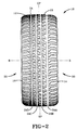
- Fig. 2 is a front view of the tread illustrated in Fig. 1.
- Fig. 3 is a plan view of a portion of the tread illustrated in Figs. 1 and 2.
- Fig. 4 is a cross-sectional view of a tire taken along a plane passing through the tire's axis of rotation, the tire incorporating a tread according to the invention.
-
- With reference to Figs. 1-4, a
tread 12 according to the present invention is illustrated. Thetread 12 is annularly attached to atire 10. Thetread 12 as illustrated is asymmetric and non-directional. - An asymmetric tread is a tread that has a tread pattern not symmetrical about the centerplane or equatorial plane EP of the tire.
- A non-directional tread is a tread that has no preferred direction of forward travel and is not required to be positioned on a vehicle in a specific wheel position or positions to ensure that the tread pattern is aligned with the preferred direction of travel.
- The conventional passenger tire also has a tread pattern that is symmetrical relative to the centerplane of the tread. This allows the tire to be mounted on either side of the vehicle regardless of the direction of travel. This symmetry of design does not take in account that design loads and requirements might be different at different tire locations on the vehicle.
- The use of a tire with asymmetric tread means that there are tires designed to be mounted on the left side of the vehicle and there are tires designed to be mounted on the right side of the vehicle. This means each tire tread design can be optimized to accommodate the requirements of the vehicle on either side of the vehicle. The design of the tire tread may vary across the width of the tread so that capabilities of the different regions of the tread width may be varied to enhance tire performance.
- The
tread 12 illustrated in Figs. 1-4 is one example of a asymmetric and non-directional tread design according to the present invention. - The
tread 12, when configured annularly, has an axis of rotation R, first and secondlateral edges 14,16 acentral portion 18 therebetween. The firstlateral edge 14 is toward the outside or outboard side of the vehicle while the secondlateral edge 16 is designed to be mounted inboard or toward the inside of the vehicle. - The
tread 12 has a plurality of groundengaging tread elements 22 separated bycircumferential grooves 24 andlateral grooves 28. Thelateral grooves 28 may intersect and join to form a continuous lateral groove path across the entire tread width. Alternatively thelateral grooves 28 may be laterally or circumferentially spaced and never connecting, or may meet at a groove. - The
tread 12 as illustrated in Figs. 1-4 has a net contact area of 65% measured from tread lateral edge to tread lateral edge. It is believed that the invention can be successfully practiced with treads having net contact areas between 62% and 68%. Thetread 12 is divided laterally into afirst tread half 30 and asecond tread half 32. Thefirst tread half 30 is located between the firstlateral edge 14 and the tire's equatorial plane EP. Thesecond tread half 32 extends from the secondlateral edge 16 to the equatorial plane EP. - The outer or
first tread half 30 is intended to be mounted on the outer or outboard side of the vehicle (not shown). While thefirst tread half 30 has an equivalent net contact area to thesecond tread half 32, thefirst tread half 30 has a higher circumferential and lateral tread stiffness than thesecond tread half 32. In the preferred embodiment, the average lateral tread stiffness of thefirst tread half 30 is 400 N/mm (2267 lb/in) while the average lateral tread stiffness of thesecond tread half 32 is 200 N/mm (1169 lb/in). Further, in the preferred embodiment, the average circumferential tread stiffness of thefirst tread half 30 is 300 N/mm (1709 lb/in) while the average tread stiffness of thesecond tread half 32 is 200 N/mm (1169 lb/in). Therefore, the average tread stiffness of thefirst tread half 30 is approximately 70% higher than the average tread stiffness of thesecond tread half 32. It is believed the invention is best practiced when the stiffness of thefirst tread half 30 is between 50% and 100% higher than the average tread stiffness of thesecond tread half 32. The higher tread stiffness in thefirst tread half 30 should provide excellent tread wear and traction while the lower tread stiffness in the inboard orsecond tread half 32 provides excellent wet, snow and mud traction. - With reference to the Figures, especially Fig. 3, one of the important features of the preferred embodiment
inventive tire 10 is the fact that the net contact area is constant in thefirst tread half 30 and thesecond tread half 32 even though the tread stiffness in thefirst tread half 30 is higher than thesecond tread half 32. This is accomplished by progressively narrowing thecircumferential groove widths 24 from the firstlateral edge 14 of thetread 12 to the secondlateral edge 16 of thetread 12. For example, with reference to Fig. 3, the fourcircumferential grooves 24 are designated 24A,24B,24C,24D.Circumferential groove 24A is the closest to the firstlateral edge 14 and is the widest circumferential grooves. The nextcircumferential groove 24B is slightly narrower thancircumferential groove 24A. The next circumferential groove moving inwardly toward the secondlateral edge 16 of thetread 12 iscircumferential groove 24C, and it is narrower yet. The narrowestcircumferential groove 24D is the circumferential groove nearest the secondlateral edge 16 of thetread 12. - Similarly, but in the opposite direction, the average width of the
lateral grooves 28 increases when moving from the firstlateral edge 14 of thetread 12 to the secondlateral edge 16 of thetread 12. For example, the lateral groove closest to the firstlateral edge 14 of thetread 12 is lateral groove 28A. Lateral groove 28A is narrower than the other lateral grooves. The next lateral groove, moving toward the secondlateral edge 16 of thetread 12, islateral groove 28B which is wider than lateral groove 28A. Similarly, continuing to move laterally across the tread width toward the secondlateral edge 16 of thetread 12, the next lateral groove is 28C which is wider yet thanlateral groove 28B. The process continues until the widestlateral grooves 28E are reached. - With reference to Fig. 4, another important feature of the
tread 12 will be illustrated. The fourcircumferential grooves lateral edge 16 to the firstlateral edge 14 is evident. It is also evident that the outboard side 36 of some of thecircumferential grooves 24 is tapered. For example, with reference tocircumferential groove 24D, both theinboard side 38D and theoutboard side 36D of thegroove 24D have the same degree of taper. In contrast, theoutboard sides circumferential grooves inboard sides circumferential grooves same grooves outboard side circumferential grooves tire 10 while theinboard side same grooves tire 10. In a preferred embodiment, both theoutboard side 36D and theinboard side 38D of the inboardmostcircumferential groove 24D make an angle of 12° with a plane parallel to the equatorial plane EP of thetire 10. The function of the tapered sidewalls 36A,36B,36C ofcircumferential grooves tread elements 22 against the cornering forces generated by and placed upon thetread elements 22 near the firstlateral edge 14 of thetire 10. - Experimental tests under a variety of conditions were conducted with tires made according to the present invention. Commercially available tires of the same size designation as the test tires were used as a control tire. Comparisons of the inventive tires and the control tires were made under identical test conditions. The tires were used on the same vehicle for each particular trial. The tire size utilized for the test was P195/60R15. The vehicle used for all tests was a 1991 Chevrolet Camaro.
- A summary of the test results revealed the inventive tire outperformed the control tire in a variety of tests.
- A test measuring a tire's tendency to hydroplane was performed. In the test, a glass plate imbedded in a road is covered with 2 mm (.080 in) of water-based dye. The test tire passes over the plate at varying speeds and is photographed from below. Two photos are taken of each tire at each speed with one tire of each construction being tested. Each tire at varying speeds is compared with its own 3,2 km/h (2 mph) run. No hydroplaning is considered to occur at this speed. In the hydroplaning test, the inventive tire retained 72% of contact area through 130 km/h (80 mph) at 2 mm (.080 in) water depth while the control tire retained 56% of its contact area under the same conditions.
- The inventive tire was also tested for subjective noise performance. In this test, the inventive tire had less tread noise and less braking growl than the control tire.
- The inventive tire also showed improvements in various handling and ride measurements. When tested for subjective harshness, the inventive tire outperformed the control tire in initial impact and impact damping qualities. The inventive tire was slightly better than the control in braking shudder and significantly better in a subjective handling evaluation, especially in steering response, response linearity and evasive maneuvering. The inventive tire was very good for steering response, having less oversteer and power on understeer than the control tire.
- It is believed that the novel features disclosed above can be easily applied to directional tread patterns as well. Although the preferred embodiment discloses a progressive narrowing or widening of groove to maintain a constant net contact ratio substantially constant from the first half to the second half it is not required that the lateral grooves progressively change widths as a function of axial distance from a lateral edge. The constant contact area simply can be achieved by adding more circumferential grooves on one tread half with a corresponding increase in lateral grooves on the opposite tread half.
- While certain representative embodiments and details have been shown for the purpose of illustrating the invention, it will be apparent to those skilled in the art that various changes and modifications can be made therein without departing from the scope of the claims.
Claims (9)
- An asymmetric tread (12) for a tire (10) wherein the tread, when configured annularly, has an axis of rotation (R), a tread width (TW), first and second lateral edges (14,16) and an equatorial plane (EP) centered between the edges, a first tread half (30) extending from the first lateral edge (14) to the equatorial plane (EP) and a second tread half (32) extending from the second lateral edge (16) to the equatorial plane (EP), the tread has a plurality of ground engaging tread elements (22) separated by a plurality of circumferentially continuous grooves (24) and a plurality of laterally extending grooves (28) each having an average groove width as measured between the ground contacting surface of the tread elements (22), the tread elements (22) in the first tread half (30) having a net contact area substantially equal to the net contact area of the tread elements (22) of the second tread half (32) as measured around the entire circumference of the tread (12) characterizedby the total of the average groove widths of the circumferential grooves (24A,24B) of the first tread half (30) being greater than the total of the average groove widths of the circumferential grooves (24C,24D) of the second tread half (32) and by the circumferential grooves (24) being progressively narrower in average groove width from the first lateral edge (14) to the second lateral edge (16); andby the total of the average groove widths of the lateral grooves (28A,28B,28C) of the first tread half (30) being less than the total of the average groove widths of the lateral grooves (28C,28D,28E) of the second tread half (32).
- The asymmetric tread (12) of claim 1 wherein the lateral grooves (28) progressively widen in average groove width from the first lateral edge (14) to the second lateral edge (16).
- The asymmetric tread (12) of claim 1 or 2 wherein the tread elements (22) adjacent the first lateral edge (14) have a lateral stiffness greater than the lateral stiffness of the tread elements (22) adjacent the second lateral edge (16).
- The asymmetric tread (12) of any of claims 1-3 wherein the tread adjacent the first lateral edge (14) has a lateral stiffness greater than the lateral stiffness of the tread adjacent the second lateral edge (16).
- The asymmetric tread (12) of any of claims 1-4 wherein the tread elements (22) adjacent the first lateral edge (14) have a circumferential stiffness greater than the circumferential stiffness of the tread elements (22) adjacent the second lateral edge (16).
- The asymmetric tread (12) of any of claims 1-5 wherein the tread adjacent the first lateral edge (14) has a circumferential stiffness greater than the circumferential stiffness of the tread adjacent the second lateral edge (16).
- The asymmetric tread (12) of any of claims 1-6 wherein at least one side of one of the circumferential grooves (24) is tapered.
- The asymmetric tread (12) of claim 7 wherein the outer side (36A,36B,36C) of the one of the circumferential grooves (24A,24B,24C) is tapered and the inner side (38A,38B,38C) of the one of the circumferential grooves (24A,24B,24C) is not tapered.
- The asymmetric tread (12) of claim 7 wherein the outer sides (36A,36B) of the circumferential grooves (24A,24B) in the first half of the tread (30) are tapered more than the outer sides (36C,36D) of the circumferential grooves (24C,24D) in the second half of the tread (32).
Applications Claiming Priority (2)
| Application Number | Priority Date | Filing Date | Title |
|---|---|---|---|
| US08/222,070 US5407005A (en) | 1994-04-04 | 1994-04-04 | Tread for a tire |
| US222070 | 1994-04-04 |
Publications (2)
| Publication Number | Publication Date |
|---|---|
| EP0678402A1 EP0678402A1 (en) | 1995-10-25 |
| EP0678402B1 true EP0678402B1 (en) | 1999-09-15 |
Family
ID=22830689
Family Applications (1)
| Application Number | Title | Priority Date | Filing Date |
|---|---|---|---|
| EP95200787A Expired - Lifetime EP0678402B1 (en) | 1994-04-04 | 1995-03-29 | A tread for a tire |
Country Status (10)
| Country | Link |
|---|---|
| US (1) | US5407005A (en) |
| EP (1) | EP0678402B1 (en) |
| JP (1) | JP3380647B2 (en) |
| KR (1) | KR100304841B1 (en) |
| CN (1) | CN1054814C (en) |
| BR (1) | BR9501234A (en) |
| CA (1) | CA2124372C (en) |
| DE (1) | DE69512123T2 (en) |
| ES (1) | ES2136791T3 (en) |
| MY (1) | MY117270A (en) |
Families Citing this family (44)
| Publication number | Priority date | Publication date | Assignee | Title |
|---|---|---|---|---|
| DE19623647A1 (en) * | 1995-06-16 | 1996-12-19 | Yokohama Rubber Co Ltd | Pneumatic tyre with reduced noise generation, but retaining grip |
| USD384618S (en) * | 1996-04-26 | 1997-10-07 | Bridgestone/Firestone, Inc. | Tire tread |
| WO1997046359A1 (en) * | 1996-06-06 | 1997-12-11 | Michelin Recherche Et Technique S.A. | Asymmetrical tire tread and method of making same |
| JP3714761B2 (en) * | 1997-03-18 | 2005-11-09 | 株式会社ブリヂストン | Pneumatic tire |
| JPH11310010A (en) * | 1998-04-28 | 1999-11-09 | Toyo Tire & Rubber Co Ltd | Pneumatic radial tire |
| US6530405B1 (en) * | 1998-08-26 | 2003-03-11 | The Goodyear Tire & Rubber Company | On/off-road tread |
| USD418785S (en) * | 1999-02-05 | 2000-01-11 | The Goodyear Tire & Rubber Company | Tire tread |
| USD421584S (en) * | 1999-02-11 | 2000-03-14 | The Goodyear & Rubber Company | Tire tread |
| USD418461S (en) * | 1999-02-26 | 2000-01-04 | The Goodyear Tire & Rubber Company | Tire tread |
| DE60012220T2 (en) * | 1999-11-30 | 2005-08-04 | Pirelli Pneumatici Società per Azioni | MULTIFONCTIONAL AIR TIRES FOR MOTOR VEHICLE |
| US6609548B2 (en) | 2000-05-11 | 2003-08-26 | Michelin Recherche Et Technique S.A. | Asymmetrical vehicle tire with balanced wet and dry performance |
| KR100390245B1 (en) * | 2000-12-28 | 2003-07-07 | 한국타이어 주식회사 | Tire having a non-symmetry type tread pattern |
| KR20030047004A (en) * | 2001-12-07 | 2003-06-18 | 금호산업주식회사 | Asymmetric Pneumatic Tire |
| KR20030054130A (en) * | 2001-12-24 | 2003-07-02 | 금호산업주식회사 | Asymmetric Pneuematic Tire |
| DE10309970A1 (en) * | 2003-03-07 | 2004-09-16 | Continental Aktiengesellschaft | Tire profile of a pneumatic vehicle tire |
| DE10312488A1 (en) * | 2003-03-20 | 2004-09-30 | Continental Aktiengesellschaft | Vehicle tires, especially winter tires with a tread pattern |
| US20050026882A1 (en) * | 2003-07-31 | 2005-02-03 | Robinson Cynthia B. | Combination of dehydroepiandrosterone or dehydroepiandrosterone-sulfate with a leukotriene receptor antagonist for treatment of asthma or chronic obstructive pulmonary disease |
| KR100633378B1 (en) * | 2003-11-25 | 2006-10-13 | 한국타이어 주식회사 | Ultra high performance asymmetry tire structure |
| JP2006192929A (en) * | 2005-01-11 | 2006-07-27 | Bridgestone Corp | Pneumatic tire |
| JP4786317B2 (en) * | 2005-12-05 | 2011-10-05 | 株式会社ブリヂストン | Pneumatic radial tire |
| JP5161478B2 (en) * | 2007-04-19 | 2013-03-13 | 住友ゴム工業株式会社 | Pneumatic tire |
| CN101678720B (en) * | 2007-05-16 | 2012-09-05 | 株式会社普利司通 | Pneumatic tire |
| JP5181581B2 (en) * | 2007-08-29 | 2013-04-10 | 横浜ゴム株式会社 | Pneumatic tire |
| US9108469B2 (en) * | 2007-10-01 | 2015-08-18 | Bridgestone Americas Tire Operations, Llc | Irrigation tire |
| JP4213197B1 (en) * | 2008-01-15 | 2009-01-21 | 横浜ゴム株式会社 | Pneumatic tire |
| CN102196927B (en) * | 2008-08-22 | 2013-12-18 | 株式会社普利司通 | Tire |
| US8170839B2 (en) * | 2009-04-24 | 2012-05-01 | Bridgestone Americas Tire Operations, Llc | Method of designing a tire tread |
| DE102010000210A1 (en) * | 2010-01-26 | 2011-07-28 | Continental Reifen Deutschland GmbH, 30165 | Vehicle tires |
| US9393839B2 (en) | 2010-03-29 | 2016-07-19 | Bridgestone Corporation | Tire |
| US9278582B2 (en) | 2010-12-21 | 2016-03-08 | Bridgestone Americas Tire Operations, Llc | Tire tread having developing grooves |
| FR2972962B1 (en) * | 2011-03-25 | 2013-03-29 | Michelin Soc Tech | OPTIMIZED ROLLER BELT IN WEAR FOR HEAVYWEIGHT TIRE |
| JP5503622B2 (en) * | 2011-11-08 | 2014-05-28 | 住友ゴム工業株式会社 | Pneumatic tire |
| US9616716B2 (en) | 2011-12-14 | 2017-04-11 | Bridgestone Americas Tire Operations, Llc | Three dimensional sipe |
| JP5406911B2 (en) * | 2011-12-28 | 2014-02-05 | 住友ゴム工業株式会社 | Pneumatic tire |
| CN104936795B (en) * | 2013-01-28 | 2018-11-30 | 倍耐力轮胎股份公司 | Tire for improving the method for the control to the ground grip ability of tire and being obtained according to this method |
| US9033011B1 (en) * | 2013-12-09 | 2015-05-19 | The Goodyear Tire & Rubber Company | Tire comprising a tread with asymmetric groove profiles |
| JP6282930B2 (en) * | 2014-05-20 | 2018-02-21 | 株式会社ブリヂストン | Pneumatic tire |
| JP5971280B2 (en) * | 2014-06-02 | 2016-08-17 | 横浜ゴム株式会社 | Pneumatic tire |
| JP6055452B2 (en) * | 2014-10-15 | 2016-12-27 | 株式会社ブリヂストン | tire |
| JP6267622B2 (en) * | 2014-10-15 | 2018-01-24 | 株式会社ブリヂストン | tire |
| CN105216552B (en) * | 2015-10-20 | 2017-05-10 | 特拓(青岛)轮胎技术有限公司 | Tread structure of all-weather all-season tire |
| JP7099021B2 (en) * | 2018-04-10 | 2022-07-12 | 住友ゴム工業株式会社 | tire |
| JP7035769B2 (en) * | 2018-04-26 | 2022-03-15 | 住友ゴム工業株式会社 | tire |
| JP2021172324A (en) * | 2020-04-30 | 2021-11-01 | 横浜ゴム株式会社 | tire |
Family Cites Families (23)
| Publication number | Priority date | Publication date | Assignee | Title |
|---|---|---|---|---|
| DE1275396B (en) * | 1963-03-02 | 1968-08-14 | Invest In Patent Dev S A R L | Motor vehicle tires with winter tread |
| NL135847C (en) * | 1968-03-18 | |||
| FR2144622B1 (en) * | 1971-07-08 | 1974-04-05 | Michelin & Cie | |
| JPS52111104A (en) * | 1976-03-15 | 1977-09-17 | Bridgestone Corp | Pneumatic tire for heavy vehicle |
| US4456046A (en) * | 1981-05-11 | 1984-06-26 | Miller Timothy I | High-speed tires |
| US4382870A (en) * | 1981-07-06 | 1983-05-10 | Northern Petrochemical Company | Antifreeze corrosion inhibitor composition for aluminum engines |
| US4546808A (en) * | 1984-01-06 | 1985-10-15 | The Goodyear Tire & Rubber Company | Pneumatic tire |
| JPS60193704A (en) * | 1984-03-15 | 1985-10-02 | Sumitomo Rubber Ind Ltd | Aired tire |
| JPS63162308A (en) * | 1986-12-26 | 1988-07-05 | Bridgestone Corp | Flat pneumatic radial tire used for high-speed running purpose |
| JPS63305008A (en) * | 1987-06-03 | 1988-12-13 | Yokohama Rubber Co Ltd:The | Pneumatic tire |
| US5016838A (en) * | 1987-09-08 | 1991-05-21 | The Goodyear Tire & Rubber Company | Aircraft tire having asymmetric tread |
| US4823855A (en) * | 1987-11-23 | 1989-04-25 | The Goodyear Tire & Rubber Company | Pneumatic tire tread pattern |
| JPH0270506A (en) * | 1988-06-22 | 1990-03-09 | Yokohama Rubber Co Ltd:The | Pneumatic radial tire |
| DE68906861T2 (en) * | 1988-11-21 | 1993-09-09 | Sumitomo Rubber Ind | VEHICLE TIRE. |
| JPH02256502A (en) * | 1988-12-06 | 1990-10-17 | Bridgestone Corp | Heavy load pneumatic tire |
| JP2824672B2 (en) * | 1989-08-25 | 1998-11-11 | 横浜ゴム株式会社 | Pneumatic tire |
| DE69022158T2 (en) * | 1989-10-12 | 1996-04-04 | Bridgestone Corp | Radial pneumatic tire. |
| DE59006604D1 (en) * | 1989-12-29 | 1994-09-01 | Continental Ag | Tread pattern for vehicle tires. |
| JP2905929B2 (en) * | 1990-04-14 | 1999-06-14 | 東洋ゴム工業株式会社 | Pneumatic radial tire |
| JP2971960B2 (en) * | 1991-01-16 | 1999-11-08 | 住友ゴム工業株式会社 | Pneumatic tire |
| CA2058813A1 (en) * | 1991-07-26 | 1993-01-27 | Warren Lee Croyle | Tread for a tire |
| US5360043A (en) * | 1991-07-26 | 1994-11-01 | The Goodyear Tire & Rubber Company | Asymmetric tread for a tire |
| US5421387A (en) * | 1992-07-10 | 1995-06-06 | Michelin Recherche Et Technique S.A. | Asymmetrical tire tread |
-
1994
- 1994-04-04 US US08/222,070 patent/US5407005A/en not_active Expired - Lifetime
- 1994-05-26 CA CA002124372A patent/CA2124372C/en not_active Expired - Fee Related
-
1995
- 1995-03-27 JP JP06758795A patent/JP3380647B2/en not_active Expired - Lifetime
- 1995-03-28 BR BR9501234A patent/BR9501234A/en not_active IP Right Cessation
- 1995-03-28 MY MYPI95000783A patent/MY117270A/en unknown
- 1995-03-29 DE DE69512123T patent/DE69512123T2/en not_active Expired - Fee Related
- 1995-03-29 ES ES95200787T patent/ES2136791T3/en not_active Expired - Lifetime
- 1995-03-29 EP EP95200787A patent/EP0678402B1/en not_active Expired - Lifetime
- 1995-04-03 KR KR1019950007709A patent/KR100304841B1/en not_active IP Right Cessation
- 1995-04-03 CN CN95114851A patent/CN1054814C/en not_active Expired - Fee Related
Also Published As
| Publication number | Publication date |
|---|---|
| CA2124372C (en) | 2003-01-28 |
| JP3380647B2 (en) | 2003-02-24 |
| KR950031554A (en) | 1995-12-18 |
| DE69512123T2 (en) | 2000-04-27 |
| MY117270A (en) | 2004-06-30 |
| EP0678402A1 (en) | 1995-10-25 |
| DE69512123D1 (en) | 1999-10-21 |
| US5407005A (en) | 1995-04-18 |
| KR100304841B1 (en) | 2001-11-22 |
| JPH0840018A (en) | 1996-02-13 |
| BR9501234A (en) | 1995-11-21 |
| CN1113190A (en) | 1995-12-13 |
| ES2136791T3 (en) | 1999-12-01 |
| CN1054814C (en) | 2000-07-26 |
| CA2124372A1 (en) | 1995-10-05 |
Similar Documents
| Publication | Publication Date | Title |
|---|---|---|
| EP0678402B1 (en) | A tread for a tire | |
| KR100791867B1 (en) | Pneumatic tire | |
| EP0857588B1 (en) | Pneumatic tyre | |
| US5360043A (en) | Asymmetric tread for a tire | |
| EP0681929B1 (en) | A radial pneumatic light truck or automobile tire | |
| EP2927025B1 (en) | Pneumatic tire | |
| CA1315182C (en) | Pneumatic tire | |
| US6095215A (en) | Tire having tread including working rib portion | |
| EP0912355B1 (en) | A convertible tread for a radial truck or trailer tire | |
| US4977942A (en) | Pneumatic tire having defined lug groove configuration | |
| US5529101A (en) | High performance radial tire | |
| AU2014208728A1 (en) | Pneumatic tire | |
| US4993466A (en) | Radial tire for heavy duty vehicles having a grooved buffer plane outward of each tread edge | |
| US4856571A (en) | Pneumatic tire | |
| US6250353B1 (en) | On/off road tread for a tire | |
| EP3670209B1 (en) | Tread for a pneumatic tire | |
| US20210379935A1 (en) | Pneumatic Tire | |
| JPH08188015A (en) | Front and rear wheel pneumatic tire pair for vehicle | |
| CN111183046B (en) | Tyre for vehicle wheels | |
| EP1023190A1 (en) | Tread arcs for nonrotatable automobile and light truck tires | |
| CN114919340A (en) | Tyre | |
| EP0743201B1 (en) | Pneumatic tyre |
Legal Events
| Date | Code | Title | Description |
|---|---|---|---|
| PUAI | Public reference made under article 153(3) epc to a published international application that has entered the european phase |
Free format text: ORIGINAL CODE: 0009012 |
|
| 17P | Request for examination filed |
Effective date: 19950329 |
|
| AK | Designated contracting states |
Kind code of ref document: A1 Designated state(s): DE ES FR GB IT |
|
| 17Q | First examination report despatched |
Effective date: 19970224 |
|
| GRAG | Despatch of communication of intention to grant |
Free format text: ORIGINAL CODE: EPIDOS AGRA |
|
| GRAG | Despatch of communication of intention to grant |
Free format text: ORIGINAL CODE: EPIDOS AGRA |
|
| GRAH | Despatch of communication of intention to grant a patent |
Free format text: ORIGINAL CODE: EPIDOS IGRA |
|
| GRAH | Despatch of communication of intention to grant a patent |
Free format text: ORIGINAL CODE: EPIDOS IGRA |
|
| GRAA | (expected) grant |
Free format text: ORIGINAL CODE: 0009210 |
|
| AK | Designated contracting states |
Kind code of ref document: B1 Designated state(s): DE ES FR GB IT |
|
| REF | Corresponds to: |
Ref document number: 69512123 Country of ref document: DE Date of ref document: 19991021 |
|
| ET | Fr: translation filed | ||
| REG | Reference to a national code |
Ref country code: ES Ref legal event code: FG2A Ref document number: 2136791 Country of ref document: ES Kind code of ref document: T3 |
|
| ITF | It: translation for a ep patent filed |
Owner name: MODIANO & ASSOCIATI S.R.L. |
|
| PLBE | No opposition filed within time limit |
Free format text: ORIGINAL CODE: 0009261 |
|
| STAA | Information on the status of an ep patent application or granted ep patent |
Free format text: STATUS: NO OPPOSITION FILED WITHIN TIME LIMIT |
|
| 26N | No opposition filed | ||
| REG | Reference to a national code |
Ref country code: GB Ref legal event code: IF02 |
|
| PGFP | Annual fee paid to national office [announced via postgrant information from national office to epo] |
Ref country code: GB Payment date: 20060206 Year of fee payment: 12 |
|
| PGFP | Annual fee paid to national office [announced via postgrant information from national office to epo] |
Ref country code: DE Payment date: 20060330 Year of fee payment: 12 |
|
| PGFP | Annual fee paid to national office [announced via postgrant information from national office to epo] |
Ref country code: ES Payment date: 20070320 Year of fee payment: 13 |
|
| GBPC | Gb: european patent ceased through non-payment of renewal fee |
Effective date: 20070329 |
|
| PG25 | Lapsed in a contracting state [announced via postgrant information from national office to epo] |
Ref country code: DE Free format text: LAPSE BECAUSE OF NON-PAYMENT OF DUE FEES Effective date: 20071002 |
|
| PG25 | Lapsed in a contracting state [announced via postgrant information from national office to epo] |
Ref country code: GB Free format text: LAPSE BECAUSE OF NON-PAYMENT OF DUE FEES Effective date: 20070329 |
|
| PGFP | Annual fee paid to national office [announced via postgrant information from national office to epo] |
Ref country code: IT Payment date: 20080319 Year of fee payment: 14 |
|
| REG | Reference to a national code |
Ref country code: ES Ref legal event code: FD2A Effective date: 20080331 |
|
| PG25 | Lapsed in a contracting state [announced via postgrant information from national office to epo] |
Ref country code: ES Free format text: LAPSE BECAUSE OF NON-PAYMENT OF DUE FEES Effective date: 20080331 |
|
| PGFP | Annual fee paid to national office [announced via postgrant information from national office to epo] |
Ref country code: FR Payment date: 20090306 Year of fee payment: 15 |
|
| REG | Reference to a national code |
Ref country code: FR Ref legal event code: ST Effective date: 20101130 |
|
| PG25 | Lapsed in a contracting state [announced via postgrant information from national office to epo] |
Ref country code: FR Free format text: LAPSE BECAUSE OF NON-PAYMENT OF DUE FEES Effective date: 20100331 |
|
| PG25 | Lapsed in a contracting state [announced via postgrant information from national office to epo] |
Ref country code: IT Free format text: LAPSE BECAUSE OF NON-PAYMENT OF DUE FEES Effective date: 20090329 |