EP0174992B1 - Buckle fastener and method of application - Google Patents
Buckle fastener and method of application Download PDFInfo
- Publication number
- EP0174992B1 EP0174992B1 EP85901759A EP85901759A EP0174992B1 EP 0174992 B1 EP0174992 B1 EP 0174992B1 EP 85901759 A EP85901759 A EP 85901759A EP 85901759 A EP85901759 A EP 85901759A EP 0174992 B1 EP0174992 B1 EP 0174992B1
- Authority
- EP
- European Patent Office
- Prior art keywords
- strap
- retainer
- buckle
- bridge
- free end
- Prior art date
- Legal status (The legal status is an assumption and is not a legal conclusion. Google has not performed a legal analysis and makes no representation as to the accuracy of the status listed.)
- Expired - Lifetime
Links
- 238000000034 method Methods 0.000 title claims description 6
- 238000005452 bending Methods 0.000 claims description 2
- 239000000463 material Substances 0.000 description 14
- 238000009413 insulation Methods 0.000 description 8
- 229910052751 metal Inorganic materials 0.000 description 8
- 239000002184 metal Substances 0.000 description 8
- 230000000694 effects Effects 0.000 description 7
- 238000004873 anchoring Methods 0.000 description 4
- 229910052918 calcium silicate Inorganic materials 0.000 description 3
- 239000000378 calcium silicate Substances 0.000 description 3
- OYACROKNLOSFPA-UHFFFAOYSA-N calcium;dioxido(oxo)silane Chemical compound [Ca+2].[O-][Si]([O-])=O OYACROKNLOSFPA-UHFFFAOYSA-N 0.000 description 3
- 239000011810 insulating material Substances 0.000 description 2
- 230000014759 maintenance of location Effects 0.000 description 2
- 240000004760 Pimpinella anisum Species 0.000 description 1
- 238000005299 abrasion Methods 0.000 description 1
- 238000010276 construction Methods 0.000 description 1
- 238000005260 corrosion Methods 0.000 description 1
- 230000007797 corrosion Effects 0.000 description 1
- 238000003780 insertion Methods 0.000 description 1
- 230000037431 insertion Effects 0.000 description 1
- 238000009434 installation Methods 0.000 description 1
- 238000004519 manufacturing process Methods 0.000 description 1
- 230000013011 mating Effects 0.000 description 1
- 238000003825 pressing Methods 0.000 description 1
- 238000004080 punching Methods 0.000 description 1
- 230000005855 radiation Effects 0.000 description 1
- 239000007787 solid Substances 0.000 description 1
- 229910001220 stainless steel Inorganic materials 0.000 description 1
- 239000010935 stainless steel Substances 0.000 description 1
- 229920001169 thermoplastic Polymers 0.000 description 1
- 239000004416 thermosoftening plastic Substances 0.000 description 1
Images
Classifications
-
- B—PERFORMING OPERATIONS; TRANSPORTING
- B25—HAND TOOLS; PORTABLE POWER-DRIVEN TOOLS; MANIPULATORS
- B25B—TOOLS OR BENCH DEVICES NOT OTHERWISE PROVIDED FOR, FOR FASTENING, CONNECTING, DISENGAGING OR HOLDING
- B25B25/00—Implements for fastening, connecting or tensioning of wire or strip
- B25B25/005—Implements for fastening, connecting or tensioning of wire or strip for applying wire clasps to hose couplings
-
- F—MECHANICAL ENGINEERING; LIGHTING; HEATING; WEAPONS; BLASTING
- F16—ENGINEERING ELEMENTS AND UNITS; GENERAL MEASURES FOR PRODUCING AND MAINTAINING EFFECTIVE FUNCTIONING OF MACHINES OR INSTALLATIONS; THERMAL INSULATION IN GENERAL
- F16B—DEVICES FOR FASTENING OR SECURING CONSTRUCTIONAL ELEMENTS OR MACHINE PARTS TOGETHER, e.g. NAILS, BOLTS, CIRCLIPS, CLAMPS, CLIPS OR WEDGES; JOINTS OR JOINTING
- F16B2/00—Friction-grip releasable fastenings
- F16B2/02—Clamps, i.e. with gripping action effected by positive means other than the inherent resistance to deformation of the material of the fastening
- F16B2/06—Clamps, i.e. with gripping action effected by positive means other than the inherent resistance to deformation of the material of the fastening external, i.e. with contracting action
- F16B2/08—Clamps, i.e. with gripping action effected by positive means other than the inherent resistance to deformation of the material of the fastening external, i.e. with contracting action using bands
-
- F—MECHANICAL ENGINEERING; LIGHTING; HEATING; WEAPONS; BLASTING
- F16—ENGINEERING ELEMENTS AND UNITS; GENERAL MEASURES FOR PRODUCING AND MAINTAINING EFFECTIVE FUNCTIONING OF MACHINES OR INSTALLATIONS; THERMAL INSULATION IN GENERAL
- F16L—PIPES; JOINTS OR FITTINGS FOR PIPES; SUPPORTS FOR PIPES, CABLES OR PROTECTIVE TUBING; MEANS FOR THERMAL INSULATION IN GENERAL
- F16L59/00—Thermal insulation in general
- F16L59/12—Arrangements for supporting insulation from the wall or body insulated, e.g. by means of spacers between pipe and heat-insulating material; Arrangements specially adapted for supporting insulated bodies
-
- Y—GENERAL TAGGING OF NEW TECHNOLOGICAL DEVELOPMENTS; GENERAL TAGGING OF CROSS-SECTIONAL TECHNOLOGIES SPANNING OVER SEVERAL SECTIONS OF THE IPC; TECHNICAL SUBJECTS COVERED BY FORMER USPC CROSS-REFERENCE ART COLLECTIONS [XRACs] AND DIGESTS
- Y10—TECHNICAL SUBJECTS COVERED BY FORMER USPC
- Y10T—TECHNICAL SUBJECTS COVERED BY FORMER US CLASSIFICATION
- Y10T24/00—Buckles, buttons, clasps, etc.
- Y10T24/14—Bale and package ties, hose clamps
- Y10T24/1457—Metal bands
- Y10T24/1459—Separate connections
- Y10T24/1461—One piece
- Y10T24/1463—Sheet metal
- Y10T24/1467—Swedged sheet metal band connection
Definitions
- the present invention relates to metal buckle fasteners for fastening opposing ends of a strap to form an object encircling and securing strap fastener.
- Metal fasteners as opposed to fasteners made of other materials, such as thermoplastic, are characterized by the possession of many desirable properties such as: high tensile strength, high and low temperature resistance, abrasion resistance, corrosion resistance and radiation resistance.
- a high temperature insulation sheath is constructed by enclosing a high temperature steam pipe within a sheath of insulating material, such as calcium silicate, and applying fasteners along the length of the high temperature insulation sheath to fix the insulation sheath in position.
- insulating material such as calcium silicate
- the calcium silicate insulating material is fragile and must be positioned and secured in a careful manner. In view of the fragile nature of the insulation it is desirable that the installation force necessary to install a fastener be minimized, particularly in the radially inward direction.
- a seal is provided with a reduced thickness central section which is inwardly deformable by a punching operation to interlock with the underlying band.
- U.S. Patent No. 3,754,303 A further fastener is disclosed in GB-A-2,119,321
- seals which have anchoring members disposed perpendicular to the length of the strapping material.
- the strapping material is affixed to the seals by folding each end of the strapping material around a respective anchoring member.
- the first end of the strapping material is folded around a first anchoring member so that its end is disposed inwardly of the strapping material, whereby the act of tensioning the strap tends to hold the first end in place.
- the free end of the strapping material is drawn under and around a second anchoring member, folded over, and then secured beneath two opposing lugs with the distal edge of the strapping material projecting past the lugs. It should be understood that it is undesirable for the sharp distal edge of the strapping material to project past the lugs where it poses a safety hazard.
- the lugs of the above fasteners are positioned on opposing sides of the strapping material so that when deformed over the strapping material, their longitudinal axes are perpendicular to the longitudinal anis of ID 9 p tr p pping material,
- inward radially directed force which is typically applied by repeatedly striking each lug of the fastener with a hammer.
- impact force must be carefully applied to each lug to obtain a correctly deformed lug and in situations where the object to be secured is fragile even carefully applied force can damage the underlying fragile material.
- Examples of seals having impact deformable lugs disposed laterally of the strapping material are disclosed in U.S. Patent Nos. 1,855,007; 2,377,224; 2,882,934 and 194975.
- an improved fastener buckle for fastening a strap around an object to be secured; the provision of such buckle which can be simply and quickly applied with reduced risk of damaging the encircled and secured object; the provision of such buckle which as applied covers the sharp distal edge of the strap and prevents inadvertant contact with the sharp distal edge; the provision of such buckle which effects increased retention of tension initially applied to the strap; and the provision of such fastener which is simple and economical to manufacture and apply.
- the strap fastener buckle of the present invention is defined in claim 1.
- it includes first and second bridge portions partially defining first and second tubular portions, and a deformable retainer extending from the buckle intermediate the first and second bridge portions.
- a strap's first end is secured to the buckle and the strap's free end is adapted to encircle an object and pass consecutively through the first and second tubular portions.
- the free end of the strap is fastened to the buckle by bending the free end over the second bridge portion, deforming the free end between said first and second bridge portions and into position adjacent the retainer, and deforming the retainer into a position overlying the free end of the strap to retard movement of the free end from between the first and second bridge portions to fasten the free end to the buckle.
- Said retainer is disposed in a generally upright position extending above said first and second bridge portions an amount sufficient to allow said free end of said strap to be disposed adjacent to the retainer and wherein said retainer is bendable about an axis that is substantially perpendicular to a longitudinal axis of the strap secured within the buckle.
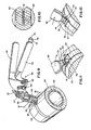
- a buckle fastener embodying the concept of the present invention is designated generally by the numeral 20 in the accompanying drawings.
- a terminated buckle 20 effects a connection between opposing ends of a metal strap 22 to form an encircling fastener that in one application can function to secure a split calcium silicate insulation sleeve 24 around a high temperature steam pipe 26.
- buckle 20 includes a first bridge portion 28, a second bridge portion 30, a C-shaped retainer 32 and two strap guidance tabs 34.
- buckle 20 is formed from stainless steel metal sheet stock which is shear formed to the configuration of planar blank 36, as seen in FIG. 3. Blank 36 is then folded relative to a medially located axis of symmetry to form tubular buckle 20, opposing edges of blank 36 abutting at seam 38.
- First and second bridge portions 28 and 30 are disposed substantially in the same plane.
- Retainer 32 extends upwardly from the inner edge of first bridge portion 28 toward said second bridge portion 30, retainer 32 substantially forming a right angle relative to first bridge portion 28.
- Retainer 32 is positioned parallel to and bends about an axis transverse to the longitudinal axis of retainer 32 forming a right angle with the longitudinal axis of buckle 20.
- Tabs 34 project inwardly, out of the plane of first and second bridge portions 28 and 30.
- L-shaped portions 40 of buckle 20 extend the length of buckle 20; L-shaped portions 40 in conjunction with respective first and second bridge portions 28 and 30 respectively define first and second tubular portions 42 and 44.
- Inset 46 is greater than one thickness of a strap deep and has an outer width of greater dimension than the width of strap 22 and an inner width of lesser dimension than the width of strap 22.
- Inset 46 tapers from its greater outer width to its lesser inner width at inwardly converging angled edges 47. As strap 22 is folded around inset 46, the edges of strap 22 move inwardly on angled edges 47 to progressively smaller widths effecting a wedging and locking deformation of the lateral edges of strap 22. The locking action of inset 46 fixes strap 22 relative to buckle 20 preventing relaxation of tension initially induced in strap 22 and thus effecting retention of tension in strap 22 while the free end of strap 22 is secured beneath retainer 32.
- inset 46 has the following dimensions: an inner width of .475 inches (1.207 centimeters); an outer width of .510 inches (1.295 centimeters); and a depth of .030 inches (.076 centimeters); where the strap has a width of .500 inches (1.270 centimeters) and a thickness of either .015 inches (.038 centimeters) or .020 inches (.051 centimeters).
- cutouts 48 are positioned on seam 38 forming edges of buckle blank 36. Cutouts 48 form a square hole in the bottom surface of buckle 20 (not shown). The square hole in mating cooperating with a protuberance (not shown) in the first end of strap 22 can be utilized to fix the first end of strap 22 to buckle 20.
- Retainer 32 includes four tines 50 which connect retainer 32 to first bridge portion 28; tines 50 being positioned in opposing pairs, with two tines 50 being positioned on opposite sides of each respective tab 34.
- An outer edge portion 52 of retainer 32 and tines 50 together form inwardly directed C-shaped retainer 32.
- the reduced area of retainer 32 at tines 50 facilitates the deformation of retainer 32.
- Retainer 32 and first bridge portion 28 together define tool engagement annulus 54.
- Tool engagement annulus 54 provides means for maintaining continuous contact with a retainer deformation tool.
- Applicator tool 56 effects termination of buckle 20 and strap 22.
- Applicator tool 56 includes handles 58 pivotally connected by bolt 60 and biased apart by spring 62.
- Spring biased ratch pawls 64 effect tensioning of strap 22 upon convergence of handles 58.
- Cylindrical strap nose 66 is rotatably carried by a mounting cylinder 68, nose 66 being removably attached thereto by retaining ring 70.
- Nose 66 is designed to abut the end of buckle 20 and pivot towards buckle 20 approximately one hundred and thirty five degrees to fold the distal end of strap 22 upward.
- Nose 66 and mounting cylinder 68 together define an aligned strap slot 72. Strap slot 72 accepts and positions strap 22.
- rotation of applicator tool handles 58 and mounting cylinder 68 secured thereto, relative to stationary nose 66 effects severance of strap 22.
- a retainer deformation tool 74 Extending from the inner handle 58 is a retainer deformation tool 74, the T-shaped end of which includes a medially extending blade 76 and a rectangular retainer abutment portion 78. As seen in FIG. 5, the T-shaped end of retainer deformation tool 74 is bent at an angle of approximately forty-five degrees to the plane of handle 58. In use, blade 76 is inserted into tool engagement annulus 54 with retainer abutment portion 78 abutting the outer face of retainer 32. Rotation of retainer deformation tool 74 in the direction shown by the solid arrow of FIGS. 11 and 12 effects a controlled levered deformation of retainer 32 from its upwardly projecting position, as shown in FIG. 11, to a position which covers and captures the distal end of strap 22, as shown in FIG. 12.
- buckle 20 is initially secured to strap 22 by inserting the buckle's inner wall between a fold in one end of strap 22, with the loose end of strap 22 exiting buckle 20 from the passageway of second tubular portion 44, as best seen in the sectional depiction of buckle 20 in FIG. 8.
- the first secured end of strap 22 is folded underneath buckle 20, with the later tensioning and termination of strap 22 securely pressing the first secured end of strap 22 between buckle 20 and the surface of the secured object.
- the free or distal end of strap 22 is positioned around the object to be secured and passed first through the passageway of first tubular portion 42 and then through the passageway of second tubular portion 44.
- Tabs 34 direct strap 22 as it exits first tubular portion 42 into second tubular portion 44, facilitating insertion of strap 22 into buckle 20.
- the distal end of strap 22 projecting from second tubular portion 44 is inserted into applicator tool 56, which is then utilized to tension strap 22, fold strap 22 over second bridge portion 30 and sever strap 22 at a predetermined point short of second bridge portion 30, to allow the distal end of strap 22 to be folded beneath retainer 32.
- retainer 32 When terminated, retainer 32 securely holds strap 22 and prevents inadvertent contact with the sharp distal edge of strap 22.
Landscapes
- Engineering & Computer Science (AREA)
- General Engineering & Computer Science (AREA)
- Mechanical Engineering (AREA)
- Buckles (AREA)
- Clamps And Clips (AREA)
- Package Frames And Binding Bands (AREA)
- Hand Tools For Fitting Together And Separating, Or Other Hand Tools (AREA)
Applications Claiming Priority (2)
| Application Number | Priority Date | Filing Date | Title |
|---|---|---|---|
| US06/591,156 US4866817A (en) | 1984-03-16 | 1984-03-16 | Buckle fastener and method of application |
| US591156 | 1990-10-01 |
Publications (3)
| Publication Number | Publication Date |
|---|---|
| EP0174992A1 EP0174992A1 (en) | 1986-03-26 |
| EP0174992A4 EP0174992A4 (en) | 1988-01-20 |
| EP0174992B1 true EP0174992B1 (en) | 1990-09-05 |
Family
ID=24365294
Family Applications (1)
| Application Number | Title | Priority Date | Filing Date |
|---|---|---|---|
| EP85901759A Expired - Lifetime EP0174992B1 (en) | 1984-03-16 | 1985-03-14 | Buckle fastener and method of application |
Country Status (7)
| Country | Link |
|---|---|
| US (1) | US4866817A (ja) |
| EP (1) | EP0174992B1 (ja) |
| JP (1) | JPH0656166B2 (ja) |
| AU (1) | AU580763B2 (ja) |
| CA (1) | CA1272871A (ja) |
| DE (1) | DE3579542D1 (ja) |
| WO (1) | WO1985004151A1 (ja) |
Families Citing this family (12)
| Publication number | Priority date | Publication date | Assignee | Title |
|---|---|---|---|---|
| US5048575A (en) * | 1989-02-06 | 1991-09-17 | Malco Products, Inc. | Strap tensioning and cut off tool |
| FR2671435B1 (fr) * | 1991-01-04 | 1995-02-03 | Axon Cable Sa | Dispositif de raccordement d'au moins une tresse de cables electriques sur un raccord. |
| GB2409643B (en) * | 2002-02-28 | 2005-09-14 | Spirent Plc | Metal banding tie |
| GB2385787B (en) * | 2002-02-28 | 2005-07-06 | Spirent Plc | Metal banding tie |
| US7171729B2 (en) * | 2003-12-05 | 2007-02-06 | Panduit Corp. | Concave buckle for strap |
| CA2507938C (en) * | 2005-05-12 | 2008-09-23 | Gazelle`S Oilfield Service Ltd. | Pipe insulation |
| US20110016673A1 (en) * | 2009-07-22 | 2011-01-27 | Band-It-Idex, Inc. | Band Seal With Selectively Deployable Locking Member |
| US8793841B2 (en) | 2010-09-02 | 2014-08-05 | Panduit Corp. | Buckle with strapping supports |
| JP2012137145A (ja) * | 2010-12-27 | 2012-07-19 | Daiwa Kasei Kogyo Kk | ベルトクランプ |
| US20160363145A1 (en) * | 2014-08-26 | 2016-12-15 | Oetiker Schweiz Ag | Band Clamp |
| JP1574623S (ja) | 2016-07-19 | 2020-04-13 | ||
| EP3523522B1 (en) * | 2016-10-04 | 2023-12-20 | Saprex, LLC | Band clamp insulation system |
Family Cites Families (21)
| Publication number | Priority date | Publication date | Assignee | Title |
|---|---|---|---|---|
| US204183A (en) * | 1878-05-28 | Improvement in bale-ties | ||
| US379878A (en) * | 1888-03-20 | Laweence | ||
| US194975A (en) * | 1877-09-11 | Improvement in bale-ties | ||
| US653337A (en) * | 1900-05-07 | 1900-07-10 | Sinclair Taliaferro | Bale-band fastening. |
| US1517515A (en) * | 1923-09-06 | 1924-12-02 | Francis L Mcgary | Box strap seal |
| US1855007A (en) * | 1930-11-20 | 1932-04-19 | Boabands Ltd | Fastener for bands and the like |
| US2192979A (en) * | 1937-09-08 | 1940-03-12 | Jr Michael J Mcaneny | Hose clamp |
| US2199744A (en) * | 1939-12-11 | 1940-05-07 | John M Gerrard | Band cutter and tensioning device |
| US2312575A (en) * | 1940-01-29 | 1943-03-02 | Punch Lok Co | Hose clamp |
| US2377224A (en) * | 1943-09-09 | 1945-05-29 | John M Gerrard | Seal |
| US2622460A (en) * | 1949-02-01 | 1952-12-23 | Packers Supply Company Ltd | Apparatus for tensioning and joining the ends of metal binding strapping, wire, and the like around a body |
| US2870503A (en) * | 1953-09-15 | 1959-01-27 | Lewis Schott | Metal strap fastening means |
| US2882934A (en) * | 1953-09-21 | 1959-04-21 | Gerrard & Co A J | Strapping tool |
| US2816337A (en) * | 1954-09-17 | 1957-12-17 | Gerrard & Co A J | Self-tensioning seal |
| US2914827A (en) * | 1958-04-15 | 1959-12-01 | Lewis M Schott | Metal strap fastening means |
| US3754303A (en) * | 1972-03-30 | 1973-08-28 | Ideal Corp | High compression band clamp |
| US3964133A (en) * | 1973-09-21 | 1976-06-22 | Amp Incorporated | Bundle tie device |
| US4015311A (en) * | 1976-04-28 | 1977-04-05 | Illinois Tool Works Inc. | Buckle with a visual tension indicator |
| US4340996A (en) * | 1979-12-21 | 1982-07-27 | Bell Telephone Laboratories, Incorporated | Adjustable cable clamp |
| GB2119321A (en) * | 1982-05-06 | 1983-11-16 | Heard Robert Arthur H | Band-securing buckle |
| US4473925A (en) * | 1982-07-12 | 1984-10-02 | Houdaille Industries, Inc. | Band clamp |
-
1984
- 1984-03-16 US US06/591,156 patent/US4866817A/en not_active Expired - Lifetime
-
1985
- 1985-03-14 WO PCT/US1985/000431 patent/WO1985004151A1/en not_active Ceased
- 1985-03-14 AU AU41127/85A patent/AU580763B2/en not_active Ceased
- 1985-03-14 EP EP85901759A patent/EP0174992B1/en not_active Expired - Lifetime
- 1985-03-14 DE DE8585901759T patent/DE3579542D1/de not_active Expired - Lifetime
- 1985-03-14 JP JP60501355A patent/JPH0656166B2/ja not_active Expired - Lifetime
- 1985-03-15 CA CA000476668A patent/CA1272871A/en not_active Expired - Fee Related
Also Published As
| Publication number | Publication date |
|---|---|
| AU580763B2 (en) | 1989-02-02 |
| JPS61501465A (ja) | 1986-07-17 |
| WO1985004151A1 (en) | 1985-09-26 |
| DE3579542D1 (de) | 1990-10-11 |
| AU4112785A (en) | 1985-10-11 |
| EP0174992A1 (en) | 1986-03-26 |
| US4866817A (en) | 1989-09-19 |
| JPH0656166B2 (ja) | 1994-07-27 |
| CA1272871A (en) | 1990-08-21 |
| EP0174992A4 (en) | 1988-01-20 |
Similar Documents
| Publication | Publication Date | Title |
|---|---|---|
| EP0174992B1 (en) | Buckle fastener and method of application | |
| US4473925A (en) | Band clamp | |
| US4235404A (en) | Cable strap | |
| US7392570B2 (en) | Concave buckle for strap | |
| KR950005553B1 (ko) | 밴드 클램프 | |
| EP0329689B1 (en) | Fastening means | |
| US4510649A (en) | Tie strip | |
| US4543691A (en) | Hose clamp | |
| CA1037685A (en) | Buckle with a visual tension indicator | |
| GB2266557A (en) | Releasable cable tie | |
| US5927497A (en) | Pack of large surface washers | |
| US6241144B1 (en) | Friction fit tab and slot shape | |
| HUE026969T2 (en) | Device for binding at least one object | |
| EP0239308A2 (en) | Improvements relating to cable ties | |
| EP0187693A2 (en) | Buckle for use with ties | |
| EP1340689A2 (en) | Metal banding tie | |
| US5226216A (en) | Method and apparatus for a cable clamp assembly | |
| GB2385787A (en) | Metal banding tie | |
| EP1190949A1 (en) | Push-type strapping seal | |
| KR960000211Y1 (ko) | 케이블 고정 클램프 | |
| JPS6211793Y2 (ja) | ||
| JPH02519Y2 (ja) | ||
| JPH0348366B2 (ja) | ||
| HK1007589B (en) | Fastening means |
Legal Events
| Date | Code | Title | Description |
|---|---|---|---|
| PUAI | Public reference made under article 153(3) epc to a published international application that has entered the european phase |
Free format text: ORIGINAL CODE: 0009012 |
|
| AK | Designated contracting states |
Kind code of ref document: A1 Designated state(s): CH DE FR GB LI NL SE |
|
| 17P | Request for examination filed |
Effective date: 19860430 |
|
| A4 | Supplementary search report drawn up and despatched |
Effective date: 19880120 |
|
| 17Q | First examination report despatched |
Effective date: 19880912 |
|
| GRAA | (expected) grant |
Free format text: ORIGINAL CODE: 0009210 |
|
| AK | Designated contracting states |
Kind code of ref document: B1 Designated state(s): CH DE FR GB LI NL SE |
|
| REF | Corresponds to: |
Ref document number: 3579542 Country of ref document: DE Date of ref document: 19901011 |
|
| ET | Fr: translation filed | ||
| PGFP | Annual fee paid to national office [announced via postgrant information from national office to epo] |
Ref country code: SE Payment date: 19910318 Year of fee payment: 7 |
|
| PGFP | Annual fee paid to national office [announced via postgrant information from national office to epo] |
Ref country code: NL Payment date: 19910331 Year of fee payment: 7 |
|
| PLBE | No opposition filed within time limit |
Free format text: ORIGINAL CODE: 0009261 |
|
| STAA | Information on the status of an ep patent application or granted ep patent |
Free format text: STATUS: NO OPPOSITION FILED WITHIN TIME LIMIT |
|
| 26N | No opposition filed | ||
| PGFP | Annual fee paid to national office [announced via postgrant information from national office to epo] |
Ref country code: CH Payment date: 19920122 Year of fee payment: 8 |
|
| PG25 | Lapsed in a contracting state [announced via postgrant information from national office to epo] |
Ref country code: SE Effective date: 19920315 |
|
| PG25 | Lapsed in a contracting state [announced via postgrant information from national office to epo] |
Ref country code: NL Effective date: 19921001 |
|
| NLV4 | Nl: lapsed or anulled due to non-payment of the annual fee | ||
| PG25 | Lapsed in a contracting state [announced via postgrant information from national office to epo] |
Ref country code: LI Effective date: 19930331 Ref country code: CH Effective date: 19930331 |
|
| REG | Reference to a national code |
Ref country code: CH Ref legal event code: PL |
|
| EUG | Se: european patent has lapsed |
Ref document number: 85901759.2 Effective date: 19921005 |
|
| REG | Reference to a national code |
Ref country code: GB Ref legal event code: IF02 |
|
| PGFP | Annual fee paid to national office [announced via postgrant information from national office to epo] |
Ref country code: FR Payment date: 20040309 Year of fee payment: 20 |
|
| PGFP | Annual fee paid to national office [announced via postgrant information from national office to epo] |
Ref country code: GB Payment date: 20040310 Year of fee payment: 20 |
|
| PGFP | Annual fee paid to national office [announced via postgrant information from national office to epo] |
Ref country code: DE Payment date: 20040325 Year of fee payment: 20 |
|
| PG25 | Lapsed in a contracting state [announced via postgrant information from national office to epo] |
Ref country code: GB Free format text: LAPSE BECAUSE OF EXPIRATION OF PROTECTION Effective date: 20050313 |
|
| REG | Reference to a national code |
Ref country code: GB Ref legal event code: PE20 |