EP0174331B1 - Systeme sanitaire pour une alimentation en eau chaude et froide - Google Patents
Systeme sanitaire pour une alimentation en eau chaude et froide Download PDFInfo
- Publication number
- EP0174331B1 EP0174331B1 EP19850901095 EP85901095A EP0174331B1 EP 0174331 B1 EP0174331 B1 EP 0174331B1 EP 19850901095 EP19850901095 EP 19850901095 EP 85901095 A EP85901095 A EP 85901095A EP 0174331 B1 EP0174331 B1 EP 0174331B1
- Authority
- EP
- European Patent Office
- Prior art keywords
- valve
- water
- tapping
- mixing
- hot
- Prior art date
- Legal status (The legal status is an assumption and is not a legal conclusion. Google has not performed a legal analysis and makes no representation as to the accuracy of the status listed.)
- Expired
Links
- XLYOFNOQVPJJNP-UHFFFAOYSA-N water Substances O XLYOFNOQVPJJNP-UHFFFAOYSA-N 0.000 title claims abstract description 166
- 238000010079 rubber tapping Methods 0.000 claims abstract description 75
- 238000003860 storage Methods 0.000 claims abstract description 25
- 239000000203 mixture Substances 0.000 claims description 7
- 239000004020 conductor Substances 0.000 claims description 6
- 238000009826 distribution Methods 0.000 claims description 3
- 238000009413 insulation Methods 0.000 claims description 3
- 230000004044 response Effects 0.000 claims description 2
- 238000010586 diagram Methods 0.000 description 8
- 239000004033 plastic Substances 0.000 description 7
- 229920003023 plastic Polymers 0.000 description 7
- 238000010276 construction Methods 0.000 description 5
- 238000009434 installation Methods 0.000 description 4
- 230000009467 reduction Effects 0.000 description 4
- RYGMFSIKBFXOCR-UHFFFAOYSA-N Copper Chemical compound [Cu] RYGMFSIKBFXOCR-UHFFFAOYSA-N 0.000 description 3
- 238000005452 bending Methods 0.000 description 3
- 229910052802 copper Inorganic materials 0.000 description 3
- 239000010949 copper Substances 0.000 description 3
- 230000000694 effects Effects 0.000 description 3
- 238000004519 manufacturing process Methods 0.000 description 3
- 238000012856 packing Methods 0.000 description 3
- 230000004075 alteration Effects 0.000 description 2
- 238000010438 heat treatment Methods 0.000 description 2
- 239000002184 metal Substances 0.000 description 2
- 229910052751 metal Inorganic materials 0.000 description 2
- 238000000034 method Methods 0.000 description 2
- 239000006223 plastic coating Substances 0.000 description 2
- 238000003825 pressing Methods 0.000 description 2
- 230000007704 transition Effects 0.000 description 2
- 230000003213 activating effect Effects 0.000 description 1
- 230000001413 cellular effect Effects 0.000 description 1
- 230000000295 complement effect Effects 0.000 description 1
- 238000005520 cutting process Methods 0.000 description 1
- 238000005265 energy consumption Methods 0.000 description 1
- 230000007794 irritation Effects 0.000 description 1
- 239000011148 porous material Substances 0.000 description 1
- 230000035939 shock Effects 0.000 description 1
Images

Classifications
-
- E—FIXED CONSTRUCTIONS
- E03—WATER SUPPLY; SEWERAGE
- E03C—DOMESTIC PLUMBING INSTALLATIONS FOR FRESH WATER OR WASTE WATER; SINKS
- E03C1/00—Domestic plumbing installations for fresh water or waste water; Sinks
- E03C1/02—Plumbing installations for fresh water
- E03C1/021—Devices for positioning or connecting of water supply lines
- E03C1/023—Devices for positioning or connecting of water supply lines with flow distribution, e.g. diverters
-
- E—FIXED CONSTRUCTIONS
- E03—WATER SUPPLY; SEWERAGE
- E03B—INSTALLATIONS OR METHODS FOR OBTAINING, COLLECTING, OR DISTRIBUTING WATER
- E03B1/00—Methods or layout of installations for water supply
- E03B1/04—Methods or layout of installations for water supply for domestic or like local supply
-
- F—MECHANICAL ENGINEERING; LIGHTING; HEATING; WEAPONS; BLASTING
- F24—HEATING; RANGES; VENTILATING
- F24D—DOMESTIC- OR SPACE-HEATING SYSTEMS, e.g. CENTRAL HEATING SYSTEMS; DOMESTIC HOT-WATER SUPPLY SYSTEMS; ELEMENTS OR COMPONENTS THEREFOR
- F24D17/00—Domestic hot-water supply systems
-
- F—MECHANICAL ENGINEERING; LIGHTING; HEATING; WEAPONS; BLASTING
- F24—HEATING; RANGES; VENTILATING
- F24D—DOMESTIC- OR SPACE-HEATING SYSTEMS, e.g. CENTRAL HEATING SYSTEMS; DOMESTIC HOT-WATER SUPPLY SYSTEMS; ELEMENTS OR COMPONENTS THEREFOR
- F24D19/00—Details
- F24D19/10—Arrangement or mounting of control or safety devices
- F24D19/1006—Arrangement or mounting of control or safety devices for water heating systems
- F24D19/1051—Arrangement or mounting of control or safety devices for water heating systems for domestic hot water
-
- F—MECHANICAL ENGINEERING; LIGHTING; HEATING; WEAPONS; BLASTING
- F24—HEATING; RANGES; VENTILATING
- F24D—DOMESTIC- OR SPACE-HEATING SYSTEMS, e.g. CENTRAL HEATING SYSTEMS; DOMESTIC HOT-WATER SUPPLY SYSTEMS; ELEMENTS OR COMPONENTS THEREFOR
- F24D3/00—Hot-water central heating systems
- F24D3/10—Feed-line arrangements, e.g. providing for heat-accumulator tanks, expansion tanks ; Hydraulic components of a central heating system
- F24D3/1058—Feed-line arrangements, e.g. providing for heat-accumulator tanks, expansion tanks ; Hydraulic components of a central heating system disposition of pipes and pipe connections
- F24D3/1066—Distributors for heating liquids
-
- G—PHYSICS
- G05—CONTROLLING; REGULATING
- G05D—SYSTEMS FOR CONTROLLING OR REGULATING NON-ELECTRIC VARIABLES
- G05D23/00—Control of temperature
- G05D23/01—Control of temperature without auxiliary power
- G05D23/13—Control of temperature without auxiliary power by varying the mixing ratio of two fluids having different temperatures
- G05D23/1393—Control of temperature without auxiliary power by varying the mixing ratio of two fluids having different temperatures characterised by the use of electric means
-
- Y—GENERAL TAGGING OF NEW TECHNOLOGICAL DEVELOPMENTS; GENERAL TAGGING OF CROSS-SECTIONAL TECHNOLOGIES SPANNING OVER SEVERAL SECTIONS OF THE IPC; TECHNICAL SUBJECTS COVERED BY FORMER USPC CROSS-REFERENCE ART COLLECTIONS [XRACs] AND DIGESTS
- Y10—TECHNICAL SUBJECTS COVERED BY FORMER USPC
- Y10T—TECHNICAL SUBJECTS COVERED BY FORMER US CLASSIFICATION
- Y10T137/00—Fluid handling
- Y10T137/6416—With heating or cooling of the system
- Y10T137/6497—Hot and cold water system having a connection from the hot to the cold channel
Definitions
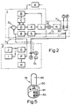
- the mixing valves which preferably are designed in the shape of separate valve units in one single central valve block, mounted adjacent or very close to the hot water heater and shall otherwise be described more in detail later in this specification. From each of the mixing valves 12a-12d extends separate pipes 14a-14d to each of the tapping locations 16a-16d, at which locations the water quantities are controlled. In a system in accordance with the invention the mixing of cold and hot water, respectively, takes place in the mixing valves 12a-12d, while the delivered water quantity is controlled by the discharge valves or faucets 16a-16d.
- the central block including the mixing valves can be made in several ways, and it is not absolutely necessary to position the central block on or adjacent the hot water storage heater, since it can alternatively be positioned at a distance from the heater, for instance in the vicinity of a number of separate tapping locations.
- a such alternative solution may be of interest if the hot water heater shall deliver hot water to separate dwelling quarters.
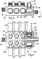
- valves In order to function in the system the valves must effectuate an alteration of the mixing proportions for cold and hot water, respectively, with maintainance of a constant flow area, and furthermore can provide a close-off of at least one of the supply ports, either for cold or for hot water.
Landscapes
- Engineering & Computer Science (AREA)
- Physics & Mathematics (AREA)
- Thermal Sciences (AREA)
- General Engineering & Computer Science (AREA)
- Mechanical Engineering (AREA)
- Combustion & Propulsion (AREA)
- Chemical & Material Sciences (AREA)
- Water Supply & Treatment (AREA)
- Health & Medical Sciences (AREA)
- Public Health (AREA)
- Hydrology & Water Resources (AREA)
- Life Sciences & Earth Sciences (AREA)
- General Physics & Mathematics (AREA)
- Automation & Control Theory (AREA)
- Multiple-Way Valves (AREA)
- Domestic Plumbing Installations (AREA)
- Domestic Hot-Water Supply Systems And Details Of Heating Systems (AREA)
- Control Of Temperature (AREA)
- Temperature-Responsive Valves (AREA)
- Devices For Dispensing Beverages (AREA)
Abstract
Claims (10)
Priority Applications (1)
| Application Number | Priority Date | Filing Date | Title |
|---|---|---|---|
| AT85901095T ATE38090T1 (de) | 1984-02-22 | 1985-02-21 | Sanitaeres system zur lieferung von warm- und kaltwasser. |
Applications Claiming Priority (2)
| Application Number | Priority Date | Filing Date | Title |
|---|---|---|---|
| NO840670A NO155261C (no) | 1984-02-22 | 1984-02-22 | Sanitaersystem for levering av varmt og kaldt vann. |
| NO840670 | 1984-02-22 |
Publications (2)
| Publication Number | Publication Date |
|---|---|
| EP0174331A1 EP0174331A1 (fr) | 1986-03-19 |
| EP0174331B1 true EP0174331B1 (fr) | 1988-10-19 |
Family
ID=19887501
Family Applications (1)
| Application Number | Title | Priority Date | Filing Date |
|---|---|---|---|
| EP19850901095 Expired EP0174331B1 (fr) | 1984-02-22 | 1985-02-21 | Systeme sanitaire pour une alimentation en eau chaude et froide |
Country Status (7)
| Country | Link |
|---|---|
| US (1) | US4688273A (fr) |
| EP (1) | EP0174331B1 (fr) |
| DE (1) | DE3565717D1 (fr) |
| DK (1) | DK156748C (fr) |
| FI (1) | FI81192C (fr) |
| NO (1) | NO155261C (fr) |
| WO (1) | WO1985003764A1 (fr) |
Families Citing this family (36)
| Publication number | Priority date | Publication date | Assignee | Title |
|---|---|---|---|---|
| DE3531294A1 (de) * | 1985-09-02 | 1987-03-12 | Knebel & Roettger Fa | Verfahren und schaltungsanordnung zur steuerung einer mischbatterie |
| US6965815B1 (en) | 1987-05-27 | 2005-11-15 | Bilboa Instruments, Inc. | Spa control system |
| US5361215A (en) | 1987-05-27 | 1994-11-01 | Siege Industries, Inc. | Spa control system |
| US4756030A (en) * | 1987-09-23 | 1988-07-12 | Juliver Steven J | Bathroom controller |
| EP0446862A3 (en) * | 1990-03-12 | 1994-06-29 | Toto Ltd | Shower apparatus |
| GB2261694B (en) * | 1991-10-22 | 1995-07-05 | Peter Allen Kensell | Water distribution system |
| US5329650A (en) * | 1992-03-06 | 1994-07-19 | Herman Miller, Inc. | Shower stall control column |
| AT402575B (de) * | 1994-10-31 | 1997-06-25 | Vaillant Gmbh | Verfahren zur steuerung eines volumenstrombegrenzers |
| US5746240A (en) * | 1996-10-17 | 1998-05-05 | Ayotte; Leo | Freeze protection system for car washer units |
| EP0900556B1 (fr) * | 1997-09-04 | 2004-03-10 | Aluvo Co., Ltd | Dispositif pour laver un corps humain sur un brancard |
| US6021803A (en) * | 1998-05-11 | 2000-02-08 | Nutsos; Mikael | Tapping point including a mixer for cold and hot water |
| US5979776A (en) * | 1998-05-21 | 1999-11-09 | Williams; Roderick A. | Water flow and temperature controller for a bathtub faucet |
| US6328219B1 (en) | 2000-03-01 | 2001-12-11 | Conbraco Industries, Inc. | Temperature-responsive mixing valve |
| WO2003023155A1 (fr) * | 2001-09-13 | 2003-03-20 | Paolo Andreotti | Installation sanitaire demontable a tuyau unique |
| GB0201091D0 (en) * | 2002-01-18 | 2002-03-06 | Reliance Water Controls Ltd | Water temperature control |
| US7477950B2 (en) | 2004-09-28 | 2009-01-13 | Dymocom, Inc. | Method and system for controlling a network of water appliances |
| EP1724401A3 (fr) * | 2005-05-06 | 2007-08-29 | Paolo Andreotti | Mitigeur à contrôle électrique |
| GB2432115A (en) * | 2005-06-17 | 2007-05-16 | Matthew Dickson | Water mixer and apparatus for hydrotherapy |
| US7624757B2 (en) * | 2006-11-09 | 2009-12-01 | Masco Corporation Of Indiana | Dual function handles for a faucet assembly |
| US8438672B2 (en) | 2005-11-11 | 2013-05-14 | Masco Corporation Of Indiana | Integrated electronic shower system |
| US7802733B2 (en) * | 2007-01-05 | 2010-09-28 | Masco Corporation Of Indiana | Fluid delivery control system |
| EP2306099A2 (fr) * | 2008-04-23 | 2011-04-06 | PIP Co., Ltd | Système d'alimentation d'eau mélangée à température commandée et d'alimentation d'eau chaude/froide |
| CA3096237C (fr) | 2010-11-04 | 2023-01-24 | Magarl, Llc | Soupape de commande electrohydraulique thermostatique |
| CH704188B1 (de) * | 2010-12-06 | 2023-06-30 | Eliane Zoccolillo Luethi | Ventilloser Armatursockel und ventillose aufsteckbare Armatur. |
| CH704187B1 (de) * | 2010-12-06 | 2021-11-15 | Eliane Zoccolillo Luethi | Sanitärsystem mit einer Mischzentrale. |
| US9268342B2 (en) | 2011-06-15 | 2016-02-23 | General Electric Company | Water heater with integral thermal mixing valve assembly and method |
| ES2397897B1 (es) * | 2011-07-18 | 2014-01-17 | Bnstar Innovations, S.L. | Sistema de control de agua sanitaria. |
| WO2013134525A2 (fr) | 2012-03-07 | 2013-09-12 | Moen Incorporated | Raccord d'équipement de plomberie électronique |
| CN104245602B (zh) | 2012-09-21 | 2017-10-27 | 捷通国际有限公司 | 用于水处理系统的选择性水温部件 |
| EP2722449B1 (fr) * | 2012-10-19 | 2021-07-21 | Honeywell Technologies Sarl | Système d'eau potable |
| JP6520832B2 (ja) * | 2016-06-08 | 2019-05-29 | 株式会社デンソー | 切替弁 |
| US11060628B2 (en) | 2018-05-16 | 2021-07-13 | Bradley Fixtures Corporation | Housing for multiple mixing valves |
| USD886236S1 (en) | 2018-05-16 | 2020-06-02 | Bradley Fixtures Corporation | Housing for multiple valves |
| DE102019201263A1 (de) * | 2019-01-31 | 2020-08-06 | Gebrüder Kemper Gmbh + Co. Kg Metallwerke | Trink- und Brauchwassersystem und Verfahren zum Spülen desselben |
| IT202100017942A1 (it) * | 2021-07-07 | 2021-10-07 | Morphica S R L | Dispositivo centralizzato di distribuzione e regolazione di acqua sanitaria con assistente vocale |
| IT202100017954A1 (it) | 2021-07-07 | 2021-10-07 | Ivan Carlo Pesenti | Dispositivo centralizzato di distribuzione e regolazione di acqua sanitaria con assistente vocale |
Citations (1)
| Publication number | Priority date | Publication date | Assignee | Title |
|---|---|---|---|---|
| US2908017A (en) * | 1957-04-08 | 1959-10-13 | Charles W Whaley | Electromagnetically controlled water distribution system |
Family Cites Families (18)
| Publication number | Priority date | Publication date | Assignee | Title |
|---|---|---|---|---|
| DE147915C (fr) * | ||||
| US1698342A (en) * | 1929-01-08 | of elgin | ||
| US646887A (en) * | 1899-11-15 | 1900-04-03 | Benjamin L Stowe | Electric signaling device for hydraulic hose. |
| US2823695A (en) * | 1955-03-02 | 1958-02-18 | Victor F Scholz | Hot water system and controls therefor |
| DE1104450B (de) * | 1955-12-31 | 1961-04-06 | Elektro Hydraulik A Knoll | Wasserverbrauchsanlage mit in die Wasserleitung eingebauten elektrischen Magnetventilen |
| US3533445A (en) * | 1964-05-14 | 1970-10-13 | Donald E Kraft | Multiple passage spool valve having stepped bore |
| US3638680A (en) * | 1970-02-25 | 1972-02-01 | Hans W Kopp | Table with liquid outlet |
| FR2340424A1 (fr) * | 1976-02-05 | 1977-09-02 | Ragot Claude | Nouveau dispositif pour l'equipement de postes d'eau, notamment dans une salle d'eau telle qu'une salle de bain |
| DE2629032A1 (de) * | 1976-06-29 | 1978-01-12 | Mauz & Pfeiffer Progress | Schlauch, insbesondere saugschlauch mit einer elektrischen leitung |
| DE2824875C3 (de) * | 1978-06-07 | 1986-11-13 | Friedrich Grohe Armaturenfabrik Gmbh & Co, 5870 Hemer | Thermostatisch gesteuertes Mischventil |
| DE2841730C3 (de) * | 1978-09-26 | 1986-03-27 | Frank'sche Eisenwerke Ag, 6340 Dillenburg | Mischbatterie |
| DE2925234A1 (de) * | 1979-06-22 | 1981-05-27 | H.D. Eichelberg & Co Gmbh, 5860 Iserlohn | Regelung fuer sanitaere mischbatterien |
| US4330081A (en) * | 1979-12-03 | 1982-05-18 | General Electric Company | Water temperature control system for a clothes washing machine |
| CH647585A5 (de) * | 1980-05-20 | 1985-01-31 | Anton J Willi | Thermostatgeregelte mischbatterie fuer kalt- und warmwasser. |
| FR2494806A1 (fr) * | 1980-11-24 | 1982-05-28 | Lesourd Hugues | Dispositif d'alimentation d'appareils sanitaires en eau a temperature variable |
| DE3338604C2 (de) * | 1983-10-24 | 1986-02-13 | Klaus Dr. 8022 Grünwald Meister | Verschlußeinrichtung mit Zweiachsen-Koppelvorrichtung, Haltemagnet und Mitnehmer |
| US4563780A (en) * | 1983-06-29 | 1986-01-14 | Pollack Simcha Z | Automated bathroom |
| US4554688A (en) * | 1984-04-17 | 1985-11-26 | Puccerella Thomas J | Water saving system |
-
1984
- 1984-02-22 NO NO840670A patent/NO155261C/no unknown
-
1985
- 1985-02-21 EP EP19850901095 patent/EP0174331B1/fr not_active Expired
- 1985-02-21 DE DE8585901095T patent/DE3565717D1/de not_active Expired
- 1985-02-21 US US06/794,922 patent/US4688273A/en not_active Expired - Fee Related
- 1985-02-21 WO PCT/NO1985/000008 patent/WO1985003764A1/fr not_active Ceased
- 1985-10-18 DK DK479985A patent/DK156748C/da not_active IP Right Cessation
- 1985-10-21 FI FI854094A patent/FI81192C/fi not_active IP Right Cessation
Patent Citations (1)
| Publication number | Priority date | Publication date | Assignee | Title |
|---|---|---|---|---|
| US2908017A (en) * | 1957-04-08 | 1959-10-13 | Charles W Whaley | Electromagnetically controlled water distribution system |
Also Published As
| Publication number | Publication date |
|---|---|
| DK156748B (da) | 1989-09-25 |
| DE3565717D1 (en) | 1988-11-24 |
| FI81192C (fi) | 1990-09-10 |
| WO1985003764A1 (fr) | 1985-08-29 |
| FI81192B (fi) | 1990-05-31 |
| FI854094A0 (fi) | 1985-10-21 |
| NO155261C (no) | 1987-03-04 |
| NO840670L (no) | 1985-08-23 |
| FI854094L (fi) | 1985-10-21 |
| DK479985A (da) | 1985-10-18 |
| NO155261B (no) | 1986-11-24 |
| DK479985D0 (da) | 1985-10-18 |
| EP0174331A1 (fr) | 1986-03-19 |
| DK156748C (da) | 1990-02-05 |
| US4688273A (en) | 1987-08-25 |
Similar Documents
| Publication | Publication Date | Title |
|---|---|---|
| EP0174331B1 (fr) | Systeme sanitaire pour une alimentation en eau chaude et froide | |
| US6705534B1 (en) | Shower control system | |
| US5872891A (en) | System for providing substantially instantaneous hot water | |
| US4738280A (en) | Hot water supply system | |
| US8561913B2 (en) | Device for dispensing water with variable temperatures | |
| US6024290A (en) | Fluid tempering system | |
| WO2002080748A1 (fr) | Douche spa et dispositif de commande | |
| EP0470647A3 (fr) | Mitigeur sanitaire avec régulation thermostatique | |
| JP2023506051A (ja) | 制御装置及びその方法、ならびに水栓 | |
| CA3054111C (fr) | Procede et dispositif pour economiser l'energie calorifique et l'eau dans une installation sanitaire | |
| US20200037400A1 (en) | Electric fluid heating system and method of use thereof | |
| US4648426A (en) | Hot water supply system | |
| JP3318949B2 (ja) | 給湯装置 | |
| JPH05165533A (ja) | 給湯装置 | |
| JPH0585815B2 (fr) | ||
| CA1294851C (fr) | Systeme de plomberie a commande electrique | |
| GB2342429A (en) | Flow control for boiler of central heating/hot water system | |
| JPS61127979A (ja) | 湯水混合栓 | |
| GB2200978A (en) | Electric water heating apparatus | |
| WO1996001396A1 (fr) | Systeme de reglage de temperature d'un fluide | |
| AU2005100624A4 (en) | Water flow control system | |
| EP0094989A1 (fr) | Dispositif d'alimentation en eau chaude, système de distribution de chaleur et unité d'encastrement comprenant un tel dispositif | |
| GB2241053A (en) | Electrical continuous-flow water heater | |
| JPH0347135Y2 (fr) | ||
| JP2960246B2 (ja) | 給湯装置 |
Legal Events
| Date | Code | Title | Description |
|---|---|---|---|
| PUAI | Public reference made under article 153(3) epc to a published international application that has entered the european phase |
Free format text: ORIGINAL CODE: 0009012 |
|
| 17P | Request for examination filed |
Effective date: 19851024 |
|
| AK | Designated contracting states |
Kind code of ref document: A1 Designated state(s): AT BE CH DE FR GB LI LU NL SE |
|
| 17Q | First examination report despatched |
Effective date: 19860708 |
|
| GRAA | (expected) grant |
Free format text: ORIGINAL CODE: 0009210 |
|
| AK | Designated contracting states |
Kind code of ref document: B1 Designated state(s): AT BE CH DE FR GB LI LU NL SE |
|
| REF | Corresponds to: |
Ref document number: 38090 Country of ref document: AT Date of ref document: 19881115 Kind code of ref document: T |
|
| REF | Corresponds to: |
Ref document number: 3565717 Country of ref document: DE Date of ref document: 19881124 |
|
| ET | Fr: translation filed | ||
| PLBE | No opposition filed within time limit |
Free format text: ORIGINAL CODE: 0009261 |
|
| STAA | Information on the status of an ep patent application or granted ep patent |
Free format text: STATUS: NO OPPOSITION FILED WITHIN TIME LIMIT |
|
| 26N | No opposition filed | ||
| PGFP | Annual fee paid to national office [announced via postgrant information from national office to epo] |
Ref country code: GB Payment date: 19910215 Year of fee payment: 7 |
|
| PGFP | Annual fee paid to national office [announced via postgrant information from national office to epo] |
Ref country code: SE Payment date: 19910218 Year of fee payment: 7 |
|
| PGFP | Annual fee paid to national office [announced via postgrant information from national office to epo] |
Ref country code: LU Payment date: 19910220 Year of fee payment: 7 |
|
| PGFP | Annual fee paid to national office [announced via postgrant information from national office to epo] |
Ref country code: FR Payment date: 19910222 Year of fee payment: 7 |
|
| PGFP | Annual fee paid to national office [announced via postgrant information from national office to epo] |
Ref country code: CH Payment date: 19910227 Year of fee payment: 7 Ref country code: AT Payment date: 19910227 Year of fee payment: 7 |
|
| PGFP | Annual fee paid to national office [announced via postgrant information from national office to epo] |
Ref country code: NL Payment date: 19910228 Year of fee payment: 7 |
|
| PGFP | Annual fee paid to national office [announced via postgrant information from national office to epo] |
Ref country code: BE Payment date: 19910415 Year of fee payment: 7 |
|
| PGFP | Annual fee paid to national office [announced via postgrant information from national office to epo] |
Ref country code: DE Payment date: 19910430 Year of fee payment: 7 |
|
| EPTA | Lu: last paid annual fee | ||
| PG25 | Lapsed in a contracting state [announced via postgrant information from national office to epo] |
Ref country code: LU Free format text: LAPSE BECAUSE OF NON-PAYMENT OF DUE FEES Effective date: 19920221 Ref country code: GB Effective date: 19920221 Ref country code: AT Effective date: 19920221 |
|
| PG25 | Lapsed in a contracting state [announced via postgrant information from national office to epo] |
Ref country code: SE Effective date: 19920222 |
|
| PG25 | Lapsed in a contracting state [announced via postgrant information from national office to epo] |
Ref country code: BE Effective date: 19920228 |
|
| PG25 | Lapsed in a contracting state [announced via postgrant information from national office to epo] |
Ref country code: LI Effective date: 19920229 Ref country code: CH Effective date: 19920229 |
|
| BERE | Be: lapsed |
Owner name: LYNG INDUSTRIER A/B Effective date: 19920228 |
|
| PG25 | Lapsed in a contracting state [announced via postgrant information from national office to epo] |
Ref country code: NL Effective date: 19920901 |
|
| NLV4 | Nl: lapsed or anulled due to non-payment of the annual fee | ||
| GBPC | Gb: european patent ceased through non-payment of renewal fee | ||
| PG25 | Lapsed in a contracting state [announced via postgrant information from national office to epo] |
Ref country code: FR Effective date: 19921030 |
|
| REG | Reference to a national code |
Ref country code: CH Ref legal event code: PL |
|
| PG25 | Lapsed in a contracting state [announced via postgrant information from national office to epo] |
Ref country code: DE Effective date: 19921103 |
|
| REG | Reference to a national code |
Ref country code: FR Ref legal event code: ST |
|
| EUG | Se: european patent has lapsed |
Ref document number: 85901095.1 Effective date: 19920904 |