EP0174331B1 - Sanitary system for supply of hot and cold water - Google Patents
Sanitary system for supply of hot and cold water Download PDFInfo
- Publication number
- EP0174331B1 EP0174331B1 EP19850901095 EP85901095A EP0174331B1 EP 0174331 B1 EP0174331 B1 EP 0174331B1 EP 19850901095 EP19850901095 EP 19850901095 EP 85901095 A EP85901095 A EP 85901095A EP 0174331 B1 EP0174331 B1 EP 0174331B1
- Authority
- EP
- European Patent Office
- Prior art keywords
- valve
- water
- tapping
- mixing
- hot
- Prior art date
- Legal status (The legal status is an assumption and is not a legal conclusion. Google has not performed a legal analysis and makes no representation as to the accuracy of the status listed.)
- Expired
Links
- XLYOFNOQVPJJNP-UHFFFAOYSA-N water Substances O XLYOFNOQVPJJNP-UHFFFAOYSA-N 0.000 title claims abstract description 166
- 238000010079 rubber tapping Methods 0.000 claims abstract description 75
- 238000003860 storage Methods 0.000 claims abstract description 25
- 239000000203 mixture Substances 0.000 claims description 7
- 239000004020 conductor Substances 0.000 claims description 6
- 238000009826 distribution Methods 0.000 claims description 3
- 238000009413 insulation Methods 0.000 claims description 3
- 230000004044 response Effects 0.000 claims description 2
- 238000010586 diagram Methods 0.000 description 8
- 239000004033 plastic Substances 0.000 description 7
- 229920003023 plastic Polymers 0.000 description 7
- 238000010276 construction Methods 0.000 description 5
- 238000009434 installation Methods 0.000 description 4
- 230000009467 reduction Effects 0.000 description 4
- RYGMFSIKBFXOCR-UHFFFAOYSA-N Copper Chemical compound [Cu] RYGMFSIKBFXOCR-UHFFFAOYSA-N 0.000 description 3
- 238000005452 bending Methods 0.000 description 3
- 229910052802 copper Inorganic materials 0.000 description 3
- 239000010949 copper Substances 0.000 description 3
- 230000000694 effects Effects 0.000 description 3
- 238000004519 manufacturing process Methods 0.000 description 3
- 238000012856 packing Methods 0.000 description 3
- 230000004075 alteration Effects 0.000 description 2
- 238000010438 heat treatment Methods 0.000 description 2
- 239000002184 metal Substances 0.000 description 2
- 229910052751 metal Inorganic materials 0.000 description 2
- 238000000034 method Methods 0.000 description 2
- 239000006223 plastic coating Substances 0.000 description 2
- 238000003825 pressing Methods 0.000 description 2
- 230000007704 transition Effects 0.000 description 2
- 230000003213 activating effect Effects 0.000 description 1
- 230000001413 cellular effect Effects 0.000 description 1
- 230000000295 complement effect Effects 0.000 description 1
- 238000005520 cutting process Methods 0.000 description 1
- 238000005265 energy consumption Methods 0.000 description 1
- 230000007794 irritation Effects 0.000 description 1
- 239000011148 porous material Substances 0.000 description 1
- 230000035939 shock Effects 0.000 description 1
Images

Classifications
-
- E—FIXED CONSTRUCTIONS
- E03—WATER SUPPLY; SEWERAGE
- E03C—DOMESTIC PLUMBING INSTALLATIONS FOR FRESH WATER OR WASTE WATER; SINKS
- E03C1/00—Domestic plumbing installations for fresh water or waste water; Sinks
- E03C1/02—Plumbing installations for fresh water
- E03C1/021—Devices for positioning or connecting of water supply lines
- E03C1/023—Devices for positioning or connecting of water supply lines with flow distribution, e.g. diverters
-
- E—FIXED CONSTRUCTIONS
- E03—WATER SUPPLY; SEWERAGE
- E03B—INSTALLATIONS OR METHODS FOR OBTAINING, COLLECTING, OR DISTRIBUTING WATER
- E03B1/00—Methods or layout of installations for water supply
- E03B1/04—Methods or layout of installations for water supply for domestic or like local supply
-
- F—MECHANICAL ENGINEERING; LIGHTING; HEATING; WEAPONS; BLASTING
- F24—HEATING; RANGES; VENTILATING
- F24D—DOMESTIC- OR SPACE-HEATING SYSTEMS, e.g. CENTRAL HEATING SYSTEMS; DOMESTIC HOT-WATER SUPPLY SYSTEMS; ELEMENTS OR COMPONENTS THEREFOR
- F24D17/00—Domestic hot-water supply systems
-
- F—MECHANICAL ENGINEERING; LIGHTING; HEATING; WEAPONS; BLASTING
- F24—HEATING; RANGES; VENTILATING
- F24D—DOMESTIC- OR SPACE-HEATING SYSTEMS, e.g. CENTRAL HEATING SYSTEMS; DOMESTIC HOT-WATER SUPPLY SYSTEMS; ELEMENTS OR COMPONENTS THEREFOR
- F24D19/00—Details
- F24D19/10—Arrangement or mounting of control or safety devices
- F24D19/1006—Arrangement or mounting of control or safety devices for water heating systems
- F24D19/1051—Arrangement or mounting of control or safety devices for water heating systems for domestic hot water
-
- F—MECHANICAL ENGINEERING; LIGHTING; HEATING; WEAPONS; BLASTING
- F24—HEATING; RANGES; VENTILATING
- F24D—DOMESTIC- OR SPACE-HEATING SYSTEMS, e.g. CENTRAL HEATING SYSTEMS; DOMESTIC HOT-WATER SUPPLY SYSTEMS; ELEMENTS OR COMPONENTS THEREFOR
- F24D3/00—Hot-water central heating systems
- F24D3/10—Feed-line arrangements, e.g. providing for heat-accumulator tanks, expansion tanks ; Hydraulic components of a central heating system
- F24D3/1058—Feed-line arrangements, e.g. providing for heat-accumulator tanks, expansion tanks ; Hydraulic components of a central heating system disposition of pipes and pipe connections
- F24D3/1066—Distributors for heating liquids
-
- G—PHYSICS
- G05—CONTROLLING; REGULATING
- G05D—SYSTEMS FOR CONTROLLING OR REGULATING NON-ELECTRIC VARIABLES
- G05D23/00—Control of temperature
- G05D23/01—Control of temperature without auxiliary power
- G05D23/13—Control of temperature without auxiliary power by varying the mixing ratio of two fluids having different temperatures
- G05D23/1393—Control of temperature without auxiliary power by varying the mixing ratio of two fluids having different temperatures characterised by the use of electric means
-
- Y—GENERAL TAGGING OF NEW TECHNOLOGICAL DEVELOPMENTS; GENERAL TAGGING OF CROSS-SECTIONAL TECHNOLOGIES SPANNING OVER SEVERAL SECTIONS OF THE IPC; TECHNICAL SUBJECTS COVERED BY FORMER USPC CROSS-REFERENCE ART COLLECTIONS [XRACs] AND DIGESTS
- Y10—TECHNICAL SUBJECTS COVERED BY FORMER USPC
- Y10T—TECHNICAL SUBJECTS COVERED BY FORMER US CLASSIFICATION
- Y10T137/00—Fluid handling
- Y10T137/6416—With heating or cooling of the system
- Y10T137/6497—Hot and cold water system having a connection from the hot to the cold channel
Definitions
- the mixing valves which preferably are designed in the shape of separate valve units in one single central valve block, mounted adjacent or very close to the hot water heater and shall otherwise be described more in detail later in this specification. From each of the mixing valves 12a-12d extends separate pipes 14a-14d to each of the tapping locations 16a-16d, at which locations the water quantities are controlled. In a system in accordance with the invention the mixing of cold and hot water, respectively, takes place in the mixing valves 12a-12d, while the delivered water quantity is controlled by the discharge valves or faucets 16a-16d.
- the central block including the mixing valves can be made in several ways, and it is not absolutely necessary to position the central block on or adjacent the hot water storage heater, since it can alternatively be positioned at a distance from the heater, for instance in the vicinity of a number of separate tapping locations.
- a such alternative solution may be of interest if the hot water heater shall deliver hot water to separate dwelling quarters.
- valves In order to function in the system the valves must effectuate an alteration of the mixing proportions for cold and hot water, respectively, with maintainance of a constant flow area, and furthermore can provide a close-off of at least one of the supply ports, either for cold or for hot water.
Abstract
Description
- The present invention relates to a new sanitary system, especially a system or aggregate for delivery of hot and cold water at a plurality of outlet locations.
- Conventional sanitary systems for delivery of hot and cold water at a plurality of outlet locations, for instance in a private house, comprises a source for cold water, a hot water storage heater with a cold water supply, a piping system to the outlet locations consisting of a cold water pipe and a hot water pipe, and a mixer valve on the tapping position. The piping in the system consists frequently of a set of main pipes, and couple-wise branch pipes to the separate tapping locations. The tapping valves or mixing valves may be of the two-handle type or the one-handle type such that the user by means of two manual movements adjusts the water temperature and the water quantity, respectively.
- In recent years it has been quite usual to use socalled thermostatic mixing faucets, particularly in bathrooms such that one may pre-adjust the water temperature on a scale displaying the water temperature, and such that one may with one single handle adjust the water quantity.
- Conventional sanitary systems for delivery of hot and cold water has today reached a high quality, but known systems are still hampered with some inherent drawbacks which have proved difficult to overcome. Firstly, such sanitary systems fall rather expensive both in purchase and installation, and they require further substantial maintainance, such as replacement of valve packings etc.
- In practical use the drawback frequently occurs when tapping of hot water, that one must during the tapping several times readjust the water temperature, among others because of the heating up of the piping system. A further drawback is the creation of pressure drops, sometimes also with abrupt temperature variations, if hot water is being discharged on two or several outlets simultaneously. A further drawback is that delivery of water with high temperature to the various outlets causes a large wear on the valves and the packings.
- A more serious drawback with known systems is, however, the large heat loss which takes place due to the heating of the pipe system and the fact that by each tapping a relatively large column of hot water will remain standing unused in the piping system.
- A further substantial drawback with conventional sanitary systems of this kind is that they cause the creation of substantial piping noise and so called « water shocks •. Piping noise is created in the piping as such, particularly in connection with transitions and fittings, as well as in the mixing valves due to the inherent turbulence therein. Such piping noise has proved to be very difficult to diminish, and causes frequently irritation.
- By utilisation of thermostatically controlled mixing valves it falls simpler to tap tempered water with suitable temperature, but such armatures fall rather expensive and require substantial maintainance if the adjusting ability shall not be reduced subsequent to use over a certain time.
- The main object of the present invention generally has been to provide a new system for delivery of hot and cold water to a plurality of outlet locations. A special object for the invention has been to provide a system which results in lower installation costs, is comfortable to use and - which may involve a substantial saving in energy in connection with the consumption of hot water. A special aim for the invention has been to provide a system which makes it possible to provide quick thermostatically controlled adjustment of the water temperature at the separate discharge outlets.
- An electromagnetically controlled water distribution system is disclosed in US-A-2,908,017 (C W Whaley) in which solenoid valves for turning on and off hot and cold water supplies are incorporated in mixing valves at a location remote from the tapping locations, each tapping location being supplied from a separate mixing valve by a single respective pipeline. Switches are provided at the tapping locations for activating the solenoid valves to both turn on and off the water supply and select hot or cold water or a mixture thereof.
- According to the present invention, there is disclosed a sanitary water distribution system for supplying hot or cold water or mixtures thereof from a central location to a plurality of tapping locations, said system comprising :
- a plurality, equal to the plurality of tapping locations, of water mixing valves located at the central location and remotely from the respective tapping locations ;
- a hot water storage heater connected to supply hot water to each of said mixing valves ;
- means for supplying cold water to said hot water storage heater and to each of said mixing valves ;
- each said mixing valve having extending therefrom to a respective tapping location a respective single pipeline for the supply of water from said mixing valve ;
- each said pipeline having connected thereto, at the respective tapping location, a respective manual tapping valve for controlling the quantity of water discharged therefrom ;
- characterised by each said mixing valve being thermostatically controlled and including valve means for varying to any desired proportion the proportion of hot and cold water mixed and discharged thereby ; and further comprising man- ' ually operated means at each tapping location for selecting a desired temperature of water to be discharged by the respective said mixing valve through the respective said pipline and tapping valve ;
- display means at each tapping location and responsive to the respective said manually operated means for displaying the respective selected desired temperature ; and
- processor control means, responsive to a respective said manually operated means and operatively connected to said valve means of a respective said mixing valve, for adjusting the proportion of hot and cold water mixed and discharged by said mixing valve in response to and as a function of the desired temperature selected by said manually operated means.
- The present invention is generally based upon the feature that the water quantity and the water temperature, respectively, are adjusted by means of separate valve units, more particularly such that thermostatical adjustment of the water temperature is carried out in a mixing valve positioned at the hot water storage heater, while the water quantity is adjusted manually at the outlet location. In the system in accordance with the invention only one single pipe will normally extend from the hot water storage heater to the tapping location. A sanitary system in accordance with the invention will thus distinguish itself in that one single continuous pipe extends from the hot water storage heater to each of the tapping locations, in contrary to conventional systems where two pipes are extending to each tapping location, usually in the form of branch pipes from main pipes.
- A further important feature of the present invention is that computerized control is utilized for control of the water temperature. At the tapping location is positioned a display with knobs for adjusting the water temperature, since a computerized adjustment of the thermostatically control valve is located at the hot water storage heater, taking care of the correct mixture of hot and cold water in accordance with the temperature pre-set at the tapping location. At the tapping location one has normally only a usual single grip valve for adjustment of the water quantity.
- In accordance with a further feature of the invention the thermostatic valves for carrying out adjustment of the water temperature are provided in the shape of a number of side by side positioned valve units in one separate valve housing or central block having through-going supply passages for delivery of hot and cold water to the separate valve unit, and likewise one discharge port for thermostatically adjusted mixed water to the separate tapping locations. The central block with the thermostatic valves is suitably mounted very close or adjacent the hot water storage heater. A such solution will have several advantages. Thus, the production of the valves will fall much more reasonable than by using separate valve units, and one will obtain use- or functional advantages, among others because the central block including the valve unit will be maintained at an even temperature. Tapping of water at the separate discharge locations will in accordance with the invention be rather convenient, inasmuch as the water temperature is pre-adjusted, or it may be altered to a different desired temperature, such that one with the tapping faucet only adjusts the water quantity as desired. If the user during tapping wishes to alter the water temperature, for instance a shift to colder water, one simply presses the knob for colder water until the display is giving the desired tapping temperature. The temperature display is suitably arranged with a temperature display in the centre, and a finger knob to the left for reduction of the temperature, and a finger knob at the right side for increase of the water temperature, for instance having a scale of 2 °C for each pressing, or such that the temperature is continuously altered as long as the finger is pressing the knob. The alteration of the water temperature as such, will in accordance with the system, take place rather quickly, among others because one may in accordance with the invention utilize piping having small dimensions, for instance 15 mm in diameter, a fact which implies that the water column in the piping from the hot water storage heater will be rather small and quickly will be replaced with water having a temperature as specified on the display. A thermostatic valve used with the invention will also be quick acting, a fact which will appear from the following specification.
- A system in accordance with the invention for delivery of hot and cold water will possess a number of advantages further to those which are mentioned above. Thus, not only will the existing shortcomings and disadvantages with conventional systems be reduced or eliminated, but the system will further possess other special advantages. The piping system will thus be much simpler and more reasonable, because one can utilize much smaller pipe dimensions, simultaneously as almost all fittings, tees etc. will be absent. In spite of the fact that a separate pipe will extend all way from the water heater to the tapping location, one will altogether use a smaller accumulated piping length than in connection with a corresponding conventional system for hot and cold water where two pipes must extend all the way to each separate tapping location. Smaller and shorter pipe lengths imply reduced energy loss in the piping system, and inasmuch as the hot water is being mixed at the storage heater, one will obtain less consumption of hot water and also for this reason one will obtain a reduction of energy consumption. Since only one separate, continuous pipe extends from the hot water heater to the tapping location, one will obtain reduced flow friction and thereby also reduced pipe noise, simultaneously as the installation expenses are being reduced. In a sanitary system in accordance with the invention is preferably used small-sized copper tubing, for instance with 15 mm in diameter, of the type applied with (moulded on) an insulating plastic hose. Such tubing can be bent 90° with a bending curvature of about 35 mm without risking fracture in the tubing, a fact which renders, if possible, to omit pipe fittings in the shape of elbows etc., which again results in reduced installation costs, reduced flow friction and less piping noise. Piping noise will also be reduced because on the tapping location one will have only one single valve or faucet for adjusting the water quantity, inasmuch as the water mixture takes place in the thermostatic valve positioned at the hot water storage heater. Conventional mixing valves or batteries produce, as known, considerable noise caused by the mixing and turbulence in the valve housing. Certainly some noise will be created in the thermostatic valves located at the hot water storage heater, but these valves will firstly not be particularly noise producing, and secondly, these thermostatically controlled mixing valves will be mounted at or on to the hot water storage heater, which usually is positioned in the cellar or the like where some noise does not matter much. In regard the computer control, one may in the principle utilize systems of in per se known type. The invention shall in the following be described with reference to the accompanying drawings which illustrate some embodiments for the system, a mixing valve in accordance with the invention, and a special pipe construction, and wherein :
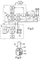
- Figure 1 shows a diagram illustrating an embodiment for the system,
- Figure 2 shows a diagram for the computerized control of the system,
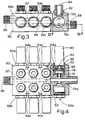
- Figures 3 and 4 show a longitudinal and a plan view respectively, partly in section, of a thermostatic mixing valve in accordance with the invention, embodied in a « central block », and
- Figure 5 shows the construction of the valve design for the valve shown in Figures 3 and 4,
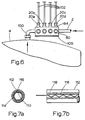
- Figure 6 illustrates the mounting of the central block valve in accordance with the invention in conjunction to a hot water storage heater, and
- Figures 7a and 7b show a special tube construction, particularly suitable for use in the system in accordance with the invention.
- Figure 1 is showing a diagram illustrating the operation of a sanitary system in accordance with the invention, for suppply of hot and cold water to a desired number of outlet locations. In the figure the reference-
number 2 designates a pipe for supply of cold water to a hotwater storage heater 4, wherefrom apipe 6 delivers hot water via abranch tube 8 to altogether four thermostatically controlled mixingvalves pipe 2 viabranch tube 10. In the diagram is for example shown four mixing valves for delivery of water to four outlets, while it will be understood that the system may be utilized for any desired number of outlet or tapping locations. The mixing valves which preferably are designed in the shape of separate valve units in one single central valve block, mounted adjacent or very close to the hot water heater and shall otherwise be described more in detail later in this specification. From each of the mixingvalves 12a-12d extendsseparate pipes 14a-14d to each of thetapping locations 16a-16d, at which locations the water quantities are controlled. In a system in accordance with the invention the mixing of cold and hot water, respectively, takes place in the mixingvalves 12a-12d, while the delivered water quantity is controlled by the discharge valves orfaucets 16a-16d. - Each of the mixing valves includes further a
temperature sensing element 20a-20d and a computerizedtemperature control unit 22a-22d including amotor 24a-24d for carrying out the mechanical adjustment of each separate mixing valve. The system includes further a computerized temperature control at each of the discharge valves, herein designated with thenumber 30. The temperature control can be carried out in accordance with any suitable method. In the illustrated solution the two uppermost outlet locations have been designated with I and II, a socalled manually operated display solution having a push-button 32 for warmer, and a push-button 34 for colder water, respectively, and a display 36 showing the desired water temperature. The system includes further preferably amicro switch 38 mounted in each faucet and which is . turned on when the faucet is closed and transmits a signal to the computer, such that same is operable to effect that the mixing valve by means of the motor is being moved to one of its extreme positions, for instance to cold water position, whereby flow of water through the mixing valve is hindered when the discharge faucet is closed. In conventional thermostatically controlled mixing valves nonreturn valves must be located preferably in the supply pipes for both cold and for hot water in order to prevent water flow through the mixing valves when the valves are in closed position. Such water flow through the valve itself will normally take place because the water pressure on the hot water side and cold water side, respectively, seldom is exactly the same. Most often the cold water side will maintain a higher pressure. A special feature of the system in accordance with the invention is that nonreturn valves can be omitted since the mixing valve will function as close-off valve. - The two lowermost tapping locations designated with III and IV, differ only from the tapping locations I and II in that the water temperature instead of being controlled by means of pushbuttons and a display, is being controlled by a pivot handle having an
internal potentiometer 39, and a temperature scale, such that one may in known fashion adjust the desired temperature on the water to be discharged. The potentiometer is via thewires computer control valves temperature sensing device 20a-d and the control orsteering motors wires 52 from astorage battery 54 which is charged automatically via a chargingunit 58 from the public power supply, preferably utilizing a voltage of 12 volt. - The computer or processor control and the various elements therein constitute today known technique and should not need any detailed description, since it is here a question about conventional products. The application thereof in the system is, however, somewhat special on background of the control functions which are desired and the system is therefore illustrated in detail in the diagram shown in Figure 2. The processor control is divided up in three sections, each of which is framed with stitched lines and designated with the
numbers Section 1 constitutes the temperature control itself,section 2 comprises the water mixing section including the temperature sensing of delivered water, while section 3 consists of the manual temperature control, and the water discharge. The processor control itself is positioned insection 1 and may be carried out with special processor cards or cartridges which are connected to each separate valve unit or in the form of one single central processor unit. Insection 1, the letter A is designating the power supply which consists of a transformer, a charging unit, and a storage battery for delivery of electric power, for instance with a voltage of 12 volt. The power supply will function independent of the city power supply in at least 10 days. The letter B designates a converter from analogue to digital value, C designates a directional selector for the motor, D designates a temperature regulator including a temperature control element D1 which is controlled from section 3 via the wire D3. Section 3 in the system is mounted on the discharge or tapping location and includes a manually operated control unit including pushbuttons J and I, for. increase and reduction of the water temperature, respectively. G is a pre-set element for defining the temperature. - H is a display which shows the desired temperature and F is a converter for operation of the display. In
section 2 the letter T designates a temperature sensing element which via the wire T2 is connected to a converter S insection 1 for converting temperature to voltage, and further is E a converter for converting from analogue to digital value. K designates an amplifier for the motor, L is a converter which converts motor ampere to voltage for delivery of power to the motors designated with the letter M insection 2. N is a gear drive and N2 designates the motor shaft which moves the valve elements until the temperature in the temperature control element T corresponds to the temperature defined by the control in section 3. The letters 0 and P designate supply pipes for hot and cold water, and the letter R likewise designates the valve for the tapping of mixed water, while 0 designates the manual maneuvering means, for instance a handle on the valve. In a preferred embodiment is further in the discharge valve mounted a microswitch Q1 (designated 38 in figure 1) which serves for switching off the temperature control when the valve is being closed. This means effects via the processor control that when the mixing valve BV is moved to one of the outermost positions, preferably the cold water position, any flow of water through the mixing valve is being hindered. The cold water position is preferred because thereby one is safeguarded against initial tapping of pure hot water, which otherwise can imply a risk for hot water scalding. - A sanitary system in accordance with the invention can be utilized for a desired number of discharge or tapping locations. In a family apartment or a private house one will usually have from four to eight tapping locations. In accordance with the invention all mixing valves for the separate tapping locations are provided in one single valve unit, preferrably realized in the form of a « central block » which is mounted close to the hot water storage heater. An embodiment for a such valve unit is illustrated in figures 3 and 4 which shows a longitudinal section and a plan view, respectively, partly in section, through a thermostatically controlled mixing valve unit in accordance with the invention, and figure 6 shows an elevation. illustrating the mounting of the central block valves in conjunction with a hot water storage heater.
- In figures 3 and 4 the
reference number 60 designates a valve block which is provided with altogether eight identical valve units, whereof fourvalve units 62a-d are located in bores on the one side of the block, while fourother valve units 64a-d are located in coaxially arranged bores on the opposite side of theblock 60. The casing or block 60 itself may consist of metal or possibly plastics. Theblock 60 is provided with aninlet 66 merging into a longitudinal bore orpassage 67 for supply of hot water to the respective valve units viabranch passages 72, 74 to the various valve bores (all not shown), and in similar fashion a cold water supply via aninlet 68 communicates with a through-going passage 69 having branch passages to each respective valve. All valves are identical andonly valve unit 64d is shown in detail on the right side of the figure 3 along sectional plane IV-IV, and shall be described in detail. In thebottom surface 71 of the bore 70branch passages 72 and 74 merge from the cold- andhot water passages 67 and 69, respectively. In thebore 70 is positioned a cylindric,pivotable valve element 76 which is shown perspectively in figure 5. The valve element has acavity 78 which in the bottom is provided with two axially extendingports water inlets 72, 74 in the valve block and which are such disposed that about 50 % area overlapping on each inlet is obtained when the respective bores or ports are in their centre position. Fromcavity 78 extends further a circumferentially positionedradial outlet 80 merging into an outlet opening 83 in the cylinder surface in thebore 70 for mixed water flowing tooutlet 84 shown in figure 3 and therefrom to a discharge or tapping position via one of thepipes 102 as shown in figure 6. - Pivotal control of the
valve element 76 is obtained by means of anelectric motor 90 which is mounted coaxially in the inlet of thebore 70 via atransition nut 92, thedrive shaft 94 on the motor being engaged with avalve stem 96 on thevalve element 76. The casing of themotor 90 includes a not shown speed reduction gear exchange in order to deliver adequate torque on the valve element. Thenumber 98 designates a packing between thenut 92 and thevalve element 76. Themotor 90 is connected to the control system which is illustrated insection 2 on the diagram shown in figure 2. - The shown central casing or block 60 is as mentioned provided with cylinders or bores for altogether eight mixing valves. If for instance need only exists for seven mixing valves, the surplus bore is blocked off with a
plug 63 which is shown in figure 4, such that thesupply ports - In figure 6 is illustrated the mounting of the
central block 60 in conjunction to a hotwater storage heater 4. Herein thenumber 100 designates the outlet for hot water from the hotwater storage heater 4 and the cold water supply is designated with thenumber 2. The supply pipes for mixed water are designated with number 102 (corresponding to thepiping 14a-c as shown in figure 1), which pipes lead to the various tapping locations. In the piping adjacent the outlets from the central block is further locatedtemperature sensing elements 20a-d as shown in figure 1. Not shown electric wiring from the same extends to theprocessor control 105 which is shown mounted on the underside of the central block. In figure 6 are shown only four outlets to the tapping locations. Altogether eightoutlet pipes 102 extend, however, from thefittings 84 as shown in figure 4. On the discharge or tapping locations are as previously stated only mounted per se conventional single flow tapping valves or faucets. If the water supply system in question for instance comprices only four tapping locations, the surplus valve bores in the centre block may instead of valve elements etc. be blocked off with close off nuts 99. - The
single pipes 102 to each tapping location in the system of the invention may have a smaller calibration or dimension than usual in connection with tempered water supply systems, among others because pairs of main pipes and branch pipes, respectively, are not needed. One may thus utilize piping having for instance 15 mm OD, which gives about 0,5 cm2 flow area. A such pipe dimension is otherwise used as standard on outlet piping on sanitary armature today, and utilization of such piping in the system in accordance with the invention will thus not reduce the smallest available flow area. - A special requirement for the sanitary system in accordance with the invention is that to each tapping location extends one preferably thermally insulated pipe, and further at least one electric conductor for the temperature control means on each tapping location. The electric conductor or wire extends suitably along with the water pipe as one single unit, but the wire ought to be somewhat longer than the piping since the wire shall be coupled to the control means at both ends of the pipe length in question. This problem is in accordance with the invention generally solved by utilizing plastic insulated metal piping, i. e. a piping provided with a layer or continuous bushing of plastics preferably provided with pores or being cellular in order to increase the thermal insulating ability thereof. In accordance with the invention the plastic layer or hose on the piping is provided with a continually extending open passage wherein, during the production of same, i. e. during the application of the plastic coating or layer on the pipe, is positioned a freely or loosely positioned electric wire which on beforehand is provided with a zig-zag or meander shape, having into effect that when cutting off the piping the end of electric wire can be pulled out and extended from its zig-zag position in the plastic insulation, such that the same can be connected to the adjacent contacts for the processor control. A such conductor solution is illustrated in figures 7a and 7b which show a cross-section and a longitudinal view, respectively, of a such piping product. The
reference number 110 designates the water pipe itself, for instance a 15 mm copper pipe, while 112 designates the plastic coating which on the inside in addition to conventional longitudinal grooves orpassages 114 are provided with alongitudinal passage 116, wherein during the production of the piping is positioned anelectric wire 118, which as shown in figure 7b . is positioned with a zig-zag shape in the pipe. Instead of a zig-zag shape the wire may for instance be given a meander shape. The aim of a such configuration is simply to provide for that the electrical wire is longer than the pipe in question. For the processor control it is sufficient to have on hand one wire along the pipe, since the pipe itself may serve as an electrical leader, but in most cases it is preferred to provide the pipe with a double or two electrical conductors. - The separate or single piping which is used with the sanitary system in accordance with the invention is preferably of the type which can be bent with a relatively small bending radius without creating a risk for that the piping is flattening. Copper piping with 15 mm diameter and provided with a plastic insulating layer is of this type. Such piping may, in contrary to conventional piping which demands special mounting fittings, elbows, tees, etc. be extended and mounted as usual electric wiring, whereby is avoided cumbersome and ugly looking piping along walls, ceilings etc. Extension of. the piping through walls etc. will furthermore be much simpler, and the frequently occurring problems in connection with expansions due to temperature variations are eliminated, since such piping is in itself quite pliable such that bendings and turns along the course of the piping will provide ample possibilities for pipe expansions.
- The temperature control means at the tapping location may be designed as special fittings on the faucet as such, or in the form of a device which for instance is mounted on the wall behind the faucet.
- It will be understood that the sanitary system in accordance with the invention can be realized in various embodiments. Thus, the central block including the mixing valves can be made in several ways, and it is not absolutely necessary to position the central block on or adjacent the hot water storage heater, since it can alternatively be positioned at a distance from the heater, for instance in the vicinity of a number of separate tapping locations. A such alternative solution may be of interest if the hot water heater shall deliver hot water to separate dwelling quarters.
- The sanitary system in accordance with the invention will be extremely easy to use. When a user operates the single flow valve at the tapping location, the same will deliver water with the temperature which is ordered to and is given on the temperature display. If water with a different temperature is desired, for instance cold water, the water temperature is adjusted accordingly by means of the manually operated knobs on the display 36, or alternatively by means of a pivotal handle if the system is based on a potentiometer as indicated in the diagram. Upon adjustment of the given temperature, the processor will immediately provide for that the motor in dependence of the defined temperature moves the
valve element 76 exactly to that position wherein the desired temperature corresponds to the temperature which is being sensed by thetemperature sensing elements 20a-20d. When the faucet is being closed, the micro-switch 38 (cf. the function diagram shown in figure 1), transmits a signal to the processor, effecting that the motor is actuated and pivots the valve element to one of the end positions. A special feature of the system in accordance with the invention is that the water mixture and the water quantity, respectively, are divided up and carried out in two separate valve units. The construction and operation of the mixing valves result in that need for check valves in the system is eliminated. Practical trials have shown that the time which lapses from the moment of opening the faucet to delivery of water with the pre-set temperature concerns only of about 5 seconds. - The shown mixing valve construction includes a pivotable valve element having bottom and lateral valve ports. It will be understood that other valve types can be utilized in the system.
- In order to function in the system the valves must effectuate an alteration of the mixing proportions for cold and hot water, respectively, with maintainance of a constant flow area, and furthermore can provide a close-off of at least one of the supply ports, either for cold or for hot water.
Claims (10)
Priority Applications (1)
| Application Number | Priority Date | Filing Date | Title |
|---|---|---|---|
| AT85901095T ATE38090T1 (en) | 1984-02-22 | 1985-02-21 | SANITARY SYSTEM FOR DELIVERY OF HOT AND COLD WATER. |
Applications Claiming Priority (2)
| Application Number | Priority Date | Filing Date | Title |
|---|---|---|---|
| NO840670A NO155261C (en) | 1984-02-22 | 1984-02-22 | SANITARY SYSTEM FOR SUPPLYING HOT AND COLD WATER. |
| NO840670 | 1984-02-22 |
Publications (2)
| Publication Number | Publication Date |
|---|---|
| EP0174331A1 EP0174331A1 (en) | 1986-03-19 |
| EP0174331B1 true EP0174331B1 (en) | 1988-10-19 |
Family
ID=19887501
Family Applications (1)
| Application Number | Title | Priority Date | Filing Date |
|---|---|---|---|
| EP19850901095 Expired EP0174331B1 (en) | 1984-02-22 | 1985-02-21 | Sanitary system for supply of hot and cold water |
Country Status (7)
| Country | Link |
|---|---|
| US (1) | US4688273A (en) |
| EP (1) | EP0174331B1 (en) |
| DE (1) | DE3565717D1 (en) |
| DK (1) | DK156748C (en) |
| FI (1) | FI81192C (en) |
| NO (1) | NO155261C (en) |
| WO (1) | WO1985003764A1 (en) |
Families Citing this family (34)
| Publication number | Priority date | Publication date | Assignee | Title |
|---|---|---|---|---|
| DE3531294A1 (en) * | 1985-09-02 | 1987-03-12 | Knebel & Roettger Fa | METHOD AND CIRCUIT FOR CONTROLLING A MIXER BATTERY |
| US4756030A (en) * | 1987-09-23 | 1988-07-12 | Juliver Steven J | Bathroom controller |
| EP0446862A3 (en) * | 1990-03-12 | 1994-06-29 | Toto Ltd | Shower apparatus |
| GB2261694B (en) * | 1991-10-22 | 1995-07-05 | Peter Allen Kensell | Water distribution system |
| US5329650A (en) * | 1992-03-06 | 1994-07-19 | Herman Miller, Inc. | Shower stall control column |
| AT402575B (en) * | 1994-10-31 | 1997-06-25 | Vaillant Gmbh | METHOD FOR CONTROLLING A VOLUME FLOW LIMITER |
| US5746240A (en) * | 1996-10-17 | 1998-05-05 | Ayotte; Leo | Freeze protection system for car washer units |
| DE69728040T2 (en) * | 1997-09-04 | 2005-02-17 | Teruo Kitamura | Device for washing human bodies on a stretcher |
| US6021803A (en) * | 1998-05-11 | 2000-02-08 | Nutsos; Mikael | Tapping point including a mixer for cold and hot water |
| US5979776A (en) * | 1998-05-21 | 1999-11-09 | Williams; Roderick A. | Water flow and temperature controller for a bathtub faucet |
| US6328219B1 (en) | 2000-03-01 | 2001-12-11 | Conbraco Industries, Inc. | Temperature-responsive mixing valve |
| WO2003023155A1 (en) * | 2001-09-13 | 2003-03-20 | Paolo Andreotti | Withdrawable single-pipe sanitary system |
| GB0201091D0 (en) * | 2002-01-18 | 2002-03-06 | Reliance Water Controls Ltd | Water temperature control |
| US7477950B2 (en) * | 2004-09-28 | 2009-01-13 | Dymocom, Inc. | Method and system for controlling a network of water appliances |
| EP1724401A3 (en) * | 2005-05-06 | 2007-08-29 | Paolo Andreotti | Electrically controlled mixing valve |
| GB2432115A (en) * | 2005-06-17 | 2007-05-16 | Matthew Dickson | Water mixer and apparatus for hydrotherapy |
| US8438672B2 (en) | 2005-11-11 | 2013-05-14 | Masco Corporation Of Indiana | Integrated electronic shower system |
| US7624757B2 (en) * | 2006-11-09 | 2009-12-01 | Masco Corporation Of Indiana | Dual function handles for a faucet assembly |
| US7802733B2 (en) * | 2007-01-05 | 2010-09-28 | Masco Corporation Of Indiana | Fluid delivery control system |
| WO2009131399A2 (en) * | 2008-04-23 | 2009-10-29 | (주) 피아이피 | Temperature-controlled mixed water and cold/hot water supply system |
| CA2756952C (en) | 2010-11-04 | 2020-12-15 | Magarl, Llc | Electrohydraulic thermostatic control valve |
| CH704188B1 (en) * | 2010-12-06 | 2023-06-30 | Eliane Zoccolillo Luethi | Valveless faucet base and valveless clip-on faucet. |
| CH704187B1 (en) * | 2010-12-06 | 2021-11-15 | Eliane Zoccolillo Luethi | Sanitary system with a mixing center. |
| US9268342B2 (en) | 2011-06-15 | 2016-02-23 | General Electric Company | Water heater with integral thermal mixing valve assembly and method |
| ES2397897B1 (en) * | 2011-07-18 | 2014-01-17 | Bnstar Innovations, S.L. | SANITARY WATER CONTROL SYSTEM. |
| CN204199385U (en) | 2012-03-07 | 2015-03-11 | 莫恩股份有限公司 | E-health appliance fitments |
| JP6321659B2 (en) | 2012-09-21 | 2018-05-09 | アクセス ビジネス グループ インターナショナル リミテッド ライアビリティ カンパニー | Selective water temperature components for use with water treatment systems |
| EP2722449B1 (en) * | 2012-10-19 | 2021-07-21 | Honeywell Technologies Sarl | Potable water system |
| JP6520832B2 (en) * | 2016-06-08 | 2019-05-29 | 株式会社デンソー | Switch valve |
| USD886236S1 (en) | 2018-05-16 | 2020-06-02 | Bradley Fixtures Corporation | Housing for multiple valves |
| WO2019222420A1 (en) | 2018-05-16 | 2019-11-21 | Bradley Fixtures Corporation | Housing for multiple valves |
| DE102019201263A1 (en) * | 2019-01-31 | 2020-08-06 | Gebrüder Kemper Gmbh + Co. Kg Metallwerke | Drinking and process water system and method for flushing the same |
| IT202100017954A1 (en) * | 2021-07-07 | 2021-10-07 | Ivan Carlo Pesenti | Centralized device for the distribution and regulation of sanitary water with voice assistant |
| IT202100017942A1 (en) * | 2021-07-07 | 2021-10-07 | Morphica S R L | Centralized device for the distribution and regulation of sanitary water with voice assistant |
Citations (1)
| Publication number | Priority date | Publication date | Assignee | Title |
|---|---|---|---|---|
| US2908017A (en) * | 1957-04-08 | 1959-10-13 | Charles W Whaley | Electromagnetically controlled water distribution system |
Family Cites Families (18)
| Publication number | Priority date | Publication date | Assignee | Title |
|---|---|---|---|---|
| DE147915C (en) * | ||||
| US1698342A (en) * | 1929-01-08 | of elgin | ||
| US646887A (en) * | 1899-11-15 | 1900-04-03 | Benjamin L Stowe | Electric signaling device for hydraulic hose. |
| US2823695A (en) * | 1955-03-02 | 1958-02-18 | Victor F Scholz | Hot water system and controls therefor |
| DE1104450B (en) * | 1955-12-31 | 1961-04-06 | Elektro Hydraulik A Knoll | Water consumption system with electric solenoid valves built into the water pipe |
| US3533445A (en) * | 1964-05-14 | 1970-10-13 | Donald E Kraft | Multiple passage spool valve having stepped bore |
| US3638680A (en) * | 1970-02-25 | 1972-02-01 | Hans W Kopp | Table with liquid outlet |
| FR2340424A1 (en) * | 1976-02-05 | 1977-09-02 | Ragot Claude | Water distribution system for bathroom - has central solenoid valve controlling control with temp. mixer and switch operated feed to each appliance |
| DE2629032A1 (en) * | 1976-06-29 | 1978-01-12 | Mauz & Pfeiffer Progress | Vacuum suction hose with electrical lead - has flexible outer cover with electrical lead wound in spiral around inner hose |
| DE2824875C3 (en) * | 1978-06-07 | 1986-11-13 | Friedrich Grohe Armaturenfabrik Gmbh & Co, 5870 Hemer | Thermostatically controlled mixing valve |
| DE2841730C3 (en) * | 1978-09-26 | 1986-03-27 | Frank'sche Eisenwerke Ag, 6340 Dillenburg | Mixer tap |
| DE2925234A1 (en) * | 1979-06-22 | 1981-05-27 | H.D. Eichelberg & Co Gmbh, 5860 Iserlohn | REGULATION FOR SANITARY MIXER BATTERIES |
| US4330081A (en) * | 1979-12-03 | 1982-05-18 | General Electric Company | Water temperature control system for a clothes washing machine |
| CH647585A5 (en) * | 1980-05-20 | 1985-01-31 | Anton J Willi | THERMOSTAT-CONTROLLED MIXER BATTERY FOR COLD AND HOT WATER. |
| FR2494806A1 (en) * | 1980-11-24 | 1982-05-28 | Lesourd Hugues | Hot and cold water mixer supplying multiple outlets - uses mixer unit with solenoid valves controlling hot and cold flow with separate valves in each outlet pipe with remote control |
| DE3338604C2 (en) * | 1983-10-24 | 1986-02-13 | Klaus Dr. 8022 Grünwald Meister | Locking device with two-axis coupling device, holding magnet and driver |
| US4563780A (en) * | 1983-06-29 | 1986-01-14 | Pollack Simcha Z | Automated bathroom |
| US4554688A (en) * | 1984-04-17 | 1985-11-26 | Puccerella Thomas J | Water saving system |
-
1984
- 1984-02-22 NO NO840670A patent/NO155261C/en unknown
-
1985
- 1985-02-21 WO PCT/NO1985/000008 patent/WO1985003764A1/en active IP Right Grant
- 1985-02-21 US US06/794,922 patent/US4688273A/en not_active Expired - Fee Related
- 1985-02-21 DE DE8585901095T patent/DE3565717D1/en not_active Expired
- 1985-02-21 EP EP19850901095 patent/EP0174331B1/en not_active Expired
- 1985-10-18 DK DK479985A patent/DK156748C/en not_active IP Right Cessation
- 1985-10-21 FI FI854094A patent/FI81192C/en not_active IP Right Cessation
Patent Citations (1)
| Publication number | Priority date | Publication date | Assignee | Title |
|---|---|---|---|---|
| US2908017A (en) * | 1957-04-08 | 1959-10-13 | Charles W Whaley | Electromagnetically controlled water distribution system |
Also Published As
| Publication number | Publication date |
|---|---|
| DK156748B (en) | 1989-09-25 |
| US4688273A (en) | 1987-08-25 |
| DE3565717D1 (en) | 1988-11-24 |
| FI854094L (en) | 1985-10-21 |
| FI81192B (en) | 1990-05-31 |
| FI854094A0 (en) | 1985-10-21 |
| EP0174331A1 (en) | 1986-03-19 |
| NO840670L (en) | 1985-08-23 |
| NO155261C (en) | 1987-03-04 |
| WO1985003764A1 (en) | 1985-08-29 |
| NO155261B (en) | 1986-11-24 |
| DK479985A (en) | 1985-10-18 |
| DK156748C (en) | 1990-02-05 |
| FI81192C (en) | 1990-09-10 |
| DK479985D0 (en) | 1985-10-18 |
Similar Documents
| Publication | Publication Date | Title |
|---|---|---|
| EP0174331B1 (en) | Sanitary system for supply of hot and cold water | |
| US6705534B1 (en) | Shower control system | |
| US5872891A (en) | System for providing substantially instantaneous hot water | |
| US4738280A (en) | Hot water supply system | |
| US8561913B2 (en) | Device for dispensing water with variable temperatures | |
| WO2002080748A1 (en) | Spa shower and controller | |
| US6024290A (en) | Fluid tempering system | |
| EP0470647A3 (en) | Sanitary mixing valve with thermostatic regulation | |
| JP2023506051A (en) | Control device and method thereof, and faucet | |
| CA3054111C (en) | Methid and device for saving heat energy and water in a sanitary facility | |
| US4648426A (en) | Hot water supply system | |
| US20200037400A1 (en) | Electric fluid heating system and method of use thereof | |
| JP3257005B2 (en) | Water heater | |
| JP3318949B2 (en) | Water heater | |
| JPH0585815B2 (en) | ||
| JPH11247260A (en) | Toilet hot water hand washer | |
| CA1294851C (en) | Electrically actuated plumbing system | |
| CN219572266U (en) | Water heater and water heating system | |
| GB2342429A (en) | Flow control for boiler of central heating/hot water system | |
| AU2005100624A4 (en) | Water flow control system | |
| JPS61127979A (en) | Combination faucet | |
| GB2200978A (en) | Electric water heating apparatus | |
| WO1996001396A1 (en) | Fluid tempering system | |
| GB2241053A (en) | Electrical continuous-flow water heater | |
| JPH0347135Y2 (en) |
Legal Events
| Date | Code | Title | Description |
|---|---|---|---|
| PUAI | Public reference made under article 153(3) epc to a published international application that has entered the european phase |
Free format text: ORIGINAL CODE: 0009012 |
|
| 17P | Request for examination filed |
Effective date: 19851024 |
|
| AK | Designated contracting states |
Kind code of ref document: A1 Designated state(s): AT BE CH DE FR GB LI LU NL SE |
|
| 17Q | First examination report despatched |
Effective date: 19860708 |
|
| GRAA | (expected) grant |
Free format text: ORIGINAL CODE: 0009210 |
|
| AK | Designated contracting states |
Kind code of ref document: B1 Designated state(s): AT BE CH DE FR GB LI LU NL SE |
|
| REF | Corresponds to: |
Ref document number: 38090 Country of ref document: AT Date of ref document: 19881115 Kind code of ref document: T |
|
| REF | Corresponds to: |
Ref document number: 3565717 Country of ref document: DE Date of ref document: 19881124 |
|
| ET | Fr: translation filed | ||
| PLBE | No opposition filed within time limit |
Free format text: ORIGINAL CODE: 0009261 |
|
| STAA | Information on the status of an ep patent application or granted ep patent |
Free format text: STATUS: NO OPPOSITION FILED WITHIN TIME LIMIT |
|
| 26N | No opposition filed | ||
| PGFP | Annual fee paid to national office [announced via postgrant information from national office to epo] |
Ref country code: GB Payment date: 19910215 Year of fee payment: 7 |
|
| PGFP | Annual fee paid to national office [announced via postgrant information from national office to epo] |
Ref country code: SE Payment date: 19910218 Year of fee payment: 7 |
|
| PGFP | Annual fee paid to national office [announced via postgrant information from national office to epo] |
Ref country code: LU Payment date: 19910220 Year of fee payment: 7 |
|
| PGFP | Annual fee paid to national office [announced via postgrant information from national office to epo] |
Ref country code: FR Payment date: 19910222 Year of fee payment: 7 |
|
| PGFP | Annual fee paid to national office [announced via postgrant information from national office to epo] |
Ref country code: CH Payment date: 19910227 Year of fee payment: 7 Ref country code: AT Payment date: 19910227 Year of fee payment: 7 |
|
| PGFP | Annual fee paid to national office [announced via postgrant information from national office to epo] |
Ref country code: NL Payment date: 19910228 Year of fee payment: 7 |
|
| PGFP | Annual fee paid to national office [announced via postgrant information from national office to epo] |
Ref country code: BE Payment date: 19910415 Year of fee payment: 7 |
|
| PGFP | Annual fee paid to national office [announced via postgrant information from national office to epo] |
Ref country code: DE Payment date: 19910430 Year of fee payment: 7 |
|
| EPTA | Lu: last paid annual fee | ||
| PG25 | Lapsed in a contracting state [announced via postgrant information from national office to epo] |
Ref country code: LU Free format text: LAPSE BECAUSE OF NON-PAYMENT OF DUE FEES Effective date: 19920221 Ref country code: GB Effective date: 19920221 Ref country code: AT Effective date: 19920221 |
|
| PG25 | Lapsed in a contracting state [announced via postgrant information from national office to epo] |
Ref country code: SE Effective date: 19920222 |
|
| PG25 | Lapsed in a contracting state [announced via postgrant information from national office to epo] |
Ref country code: BE Effective date: 19920228 |
|
| PG25 | Lapsed in a contracting state [announced via postgrant information from national office to epo] |
Ref country code: LI Effective date: 19920229 Ref country code: CH Effective date: 19920229 |
|
| BERE | Be: lapsed |
Owner name: LYNG INDUSTRIER A/B Effective date: 19920228 |
|
| PG25 | Lapsed in a contracting state [announced via postgrant information from national office to epo] |
Ref country code: NL Effective date: 19920901 |
|
| NLV4 | Nl: lapsed or anulled due to non-payment of the annual fee | ||
| GBPC | Gb: european patent ceased through non-payment of renewal fee | ||
| PG25 | Lapsed in a contracting state [announced via postgrant information from national office to epo] |
Ref country code: FR Effective date: 19921030 |
|
| REG | Reference to a national code |
Ref country code: CH Ref legal event code: PL |
|
| PG25 | Lapsed in a contracting state [announced via postgrant information from national office to epo] |
Ref country code: DE Effective date: 19921103 |
|
| REG | Reference to a national code |
Ref country code: FR Ref legal event code: ST |
|
| EUG | Se: european patent has lapsed |
Ref document number: 85901095.1 Effective date: 19920904 |