EP0172348B1 - Abdichtung - Google Patents
Abdichtung Download PDFInfo
- Publication number
- EP0172348B1 EP0172348B1 EP85107382A EP85107382A EP0172348B1 EP 0172348 B1 EP0172348 B1 EP 0172348B1 EP 85107382 A EP85107382 A EP 85107382A EP 85107382 A EP85107382 A EP 85107382A EP 0172348 B1 EP0172348 B1 EP 0172348B1
- Authority
- EP
- European Patent Office
- Prior art keywords
- band
- seal
- support
- seal according
- union
- Prior art date
- Legal status (The legal status is an assumption and is not a legal conclusion. Google has not performed a legal analysis and makes no representation as to the accuracy of the status listed.)
- Expired
Links
- 239000010410 layer Substances 0.000 claims description 13
- 239000000463 material Substances 0.000 claims description 9
- 238000007789 sealing Methods 0.000 claims description 6
- 239000012790 adhesive layer Substances 0.000 claims description 4
- 238000003466 welding Methods 0.000 claims description 4
- 230000002093 peripheral effect Effects 0.000 claims 3
- 238000004026 adhesive bonding Methods 0.000 description 3
- 230000007797 corrosion Effects 0.000 description 2
- 238000005260 corrosion Methods 0.000 description 2
- 239000000835 fiber Substances 0.000 description 2
- 239000003365 glass fiber Substances 0.000 description 2
- 238000005516 engineering process Methods 0.000 description 1
- 210000003746 feather Anatomy 0.000 description 1
- 230000012447 hatching Effects 0.000 description 1
- 238000009434 installation Methods 0.000 description 1
- 238000004519 manufacturing process Methods 0.000 description 1
- 239000002184 metal Substances 0.000 description 1
- 230000002787 reinforcement Effects 0.000 description 1
Images

Classifications
-
- F—MECHANICAL ENGINEERING; LIGHTING; HEATING; WEAPONS; BLASTING
- F16—ENGINEERING ELEMENTS AND UNITS; GENERAL MEASURES FOR PRODUCING AND MAINTAINING EFFECTIVE FUNCTIONING OF MACHINES OR INSTALLATIONS; THERMAL INSULATION IN GENERAL
- F16J—PISTONS; CYLINDERS; SEALINGS
- F16J15/00—Sealings
- F16J15/16—Sealings between relatively-moving surfaces
- F16J15/34—Sealings between relatively-moving surfaces with slip-ring pressed against a more or less radial face on one member
- F16J15/3436—Pressing means
- F16J15/3456—Pressing means without external means for pressing the ring against the face, e.g. slip-ring with a resilient lip
-
- F—MECHANICAL ENGINEERING; LIGHTING; HEATING; WEAPONS; BLASTING
- F16—ENGINEERING ELEMENTS AND UNITS; GENERAL MEASURES FOR PRODUCING AND MAINTAINING EFFECTIVE FUNCTIONING OF MACHINES OR INSTALLATIONS; THERMAL INSULATION IN GENERAL
- F16C—SHAFTS; FLEXIBLE SHAFTS; ELEMENTS OR CRANKSHAFT MECHANISMS; ROTARY BODIES OTHER THAN GEARING ELEMENTS; BEARINGS
- F16C33/00—Parts of bearings; Special methods for making bearings or parts thereof
- F16C33/72—Sealings
- F16C33/76—Sealings of ball or roller bearings
- F16C33/78—Sealings of ball or roller bearings with a diaphragm, disc, or ring, with or without resilient members
- F16C33/7886—Sealings of ball or roller bearings with a diaphragm, disc, or ring, with or without resilient members mounted outside the gap between the inner and outer races, e.g. sealing rings mounted to an end face or outer surface of a race
-
- F—MECHANICAL ENGINEERING; LIGHTING; HEATING; WEAPONS; BLASTING
- F16—ENGINEERING ELEMENTS AND UNITS; GENERAL MEASURES FOR PRODUCING AND MAINTAINING EFFECTIVE FUNCTIONING OF MACHINES OR INSTALLATIONS; THERMAL INSULATION IN GENERAL
- F16J—PISTONS; CYLINDERS; SEALINGS
- F16J15/00—Sealings
- F16J15/16—Sealings between relatively-moving surfaces
- F16J15/32—Sealings between relatively-moving surfaces with elastic sealings, e.g. O-rings
- F16J15/3268—Mounting of sealing rings
- F16J15/3272—Mounting of sealing rings the rings having a break or opening, e.g. to enable mounting on a shaft otherwise than from a shaft end
-
- F—MECHANICAL ENGINEERING; LIGHTING; HEATING; WEAPONS; BLASTING
- F16—ENGINEERING ELEMENTS AND UNITS; GENERAL MEASURES FOR PRODUCING AND MAINTAINING EFFECTIVE FUNCTIONING OF MACHINES OR INSTALLATIONS; THERMAL INSULATION IN GENERAL
- F16C—SHAFTS; FLEXIBLE SHAFTS; ELEMENTS OR CRANKSHAFT MECHANISMS; ROTARY BODIES OTHER THAN GEARING ELEMENTS; BEARINGS
- F16C19/00—Bearings with rolling contact, for exclusively rotary movement
- F16C19/02—Bearings with rolling contact, for exclusively rotary movement with bearing balls essentially of the same size in one or more circular rows
- F16C19/14—Bearings with rolling contact, for exclusively rotary movement with bearing balls essentially of the same size in one or more circular rows for both radial and axial load
- F16C19/16—Bearings with rolling contact, for exclusively rotary movement with bearing balls essentially of the same size in one or more circular rows for both radial and axial load with a single row of balls
- F16C19/163—Bearings with rolling contact, for exclusively rotary movement with bearing balls essentially of the same size in one or more circular rows for both radial and axial load with a single row of balls with angular contact
- F16C19/166—Four-point-contact ball bearings
-
- F—MECHANICAL ENGINEERING; LIGHTING; HEATING; WEAPONS; BLASTING
- F16—ENGINEERING ELEMENTS AND UNITS; GENERAL MEASURES FOR PRODUCING AND MAINTAINING EFFECTIVE FUNCTIONING OF MACHINES OR INSTALLATIONS; THERMAL INSULATION IN GENERAL
- F16C—SHAFTS; FLEXIBLE SHAFTS; ELEMENTS OR CRANKSHAFT MECHANISMS; ROTARY BODIES OTHER THAN GEARING ELEMENTS; BEARINGS
- F16C2300/00—Application independent of particular apparatuses
- F16C2300/10—Application independent of particular apparatuses related to size
- F16C2300/14—Large applications, e.g. bearings having an inner diameter exceeding 500 mm
-
- F—MECHANICAL ENGINEERING; LIGHTING; HEATING; WEAPONS; BLASTING
- F16—ENGINEERING ELEMENTS AND UNITS; GENERAL MEASURES FOR PRODUCING AND MAINTAINING EFFECTIVE FUNCTIONING OF MACHINES OR INSTALLATIONS; THERMAL INSULATION IN GENERAL
- F16C—SHAFTS; FLEXIBLE SHAFTS; ELEMENTS OR CRANKSHAFT MECHANISMS; ROTARY BODIES OTHER THAN GEARING ELEMENTS; BEARINGS
- F16C33/00—Parts of bearings; Special methods for making bearings or parts thereof
- F16C33/72—Sealings
- F16C33/76—Sealings of ball or roller bearings
-
- Y—GENERAL TAGGING OF NEW TECHNOLOGICAL DEVELOPMENTS; GENERAL TAGGING OF CROSS-SECTIONAL TECHNOLOGIES SPANNING OVER SEVERAL SECTIONS OF THE IPC; TECHNICAL SUBJECTS COVERED BY FORMER USPC CROSS-REFERENCE ART COLLECTIONS [XRACs] AND DIGESTS
- Y10—TECHNICAL SUBJECTS COVERED BY FORMER USPC
- Y10S—TECHNICAL SUBJECTS COVERED BY FORMER USPC CROSS-REFERENCE ART COLLECTIONS [XRACs] AND DIGESTS
- Y10S277/00—Seal for a joint or juncture
- Y10S277/922—Bonding or joining for manufacture of seal
Definitions
- the invention relates to a seal between two parts, one of which carries a seal made of elastic, preferably polymeric material, which consists of a hollow cylindrical support from which a sealing lip protrudes on at least one end face, which bears against the other part, the Carrier of the sealing lip rests on the one hand against a cylindrical outer surface of one part and on the other hand is surrounded by a tension band.
- Such seals are used both between mutually movable and stationary parts.
- a metal hose tie is provided as the tensioning strap, the two ends of which have radially projecting tabs through which a tensioning screw passes.
- the additional radial space required for the brackets and the clamping screw is particularly disturbing. In many cases there is no space for this.
- the arrangement of these tabs and the clamping screw at only one circumferential point creates an imbalance, which is noticeably noticeable in the case of rapidly rotating parts (FR-A-12 06 985).
- the invention has for its object to provide a seal of the type specified above, which is inexpensive to manufacture and assemble and which does not take up any additional installation space.
- the tension band is designed as an elastic band made of polymeric material, which is wound around the support of the seal and the outer free end of which is cohesively connected to the band below, such as by gluing or welding or positively.
- the seal Since the seal has a seal with a hollow cylindrical carrier, on the end face of which the sealing lip protrudes, the seal can be securely fastened to the component carrying it by means of the band spanning the carrier in the manner of a bandage, without the band incurring costs associated with would be comparable to that caused by a reinforcement ring.
- the provision of tapes with a predetermined diameter is superfluous, since the tape for seals of different diameters only has to be cut to the required length and connected at its ends.
- An embodiment of the invention provides that the band comprising the carrier is reinforced by fibers running in particular in the longitudinal direction of the band, glass fibers being particularly suitable as fibers, the length of which corresponds to that of the band.
- Another embodiment of the invention provides that the band is wound in several layers around the carrier in a spiral manner.
- a comparatively thin band can then be used, which can also have an adhesive layer on its side adjacent to the carrier, as a result of which the band is fixed to the carrier or the individual layers of the band with respect to one another and the tension of the band is also maintained.
- At least the outer layers of the tape are integrally bonded at least at one circumferential point by spot welding or by a fastening means, e.g. in the manner of a clamp, are positively connected to one another. These measures also serve to maintain the tension of the belt and to secure the individual layers of the belt relative to one another.
- one embodiment of the invention provides that the bore surface of the carrier and the cylindrical outer surface of one part are provided with projections and recesses running in the circumferential direction, which are form-fitting mesh.
- the seal Due to the specified cross-sectional shape of the seal, according to a variant of the invention, it can be replaced by a seal at its ends, e.g. be formed by gluing or vulcanizing cohesively connected section of a cross section corresponding to the profile of the seal.
- the seal is manufactured as an extruded profile, cut to the length required for the respective seal and connected at its ends, so that special seals do not have to be manufactured for seals of different diameters.
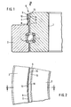
- the seal according to the invention shown in FIG. 1 is arranged between the concentrically arranged races 1 and 2 of a roller bearing rotary connection, between which balls 3 roll on running wires 4.
- the carrier 7 of the seal 6 is spanned by an elastic band 9 made of polymeric material, the ends 10 and 11 of which, as FIG. 2 shows, overlap one another.
- the mutually facing surfaces of the ends 10 and 11 are welded together.
- the seal 6 consists of a at its ends 15 and 16 e.g. by gluing or vulcanizing cohesively connected section of a cross section corresponding to the profile of the seal 6. These measures make it unnecessary to produce special seals 6 for seals of different diameters. Rather, they can be cut to the required length from the profile and connected at their ends in the manner described.
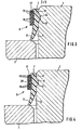
- the seals according to the invention shown in FIGS. 3 to 5 differ from the ones described above in that the band 17 or 22, which is made of a polymeric material, is spirally wound in several layers 18 or 21 around the hollow cylindrical carrier 7.
- an adhesive layer 19 is provided on the side of the band 17 facing the carrier 7, which layer serves, on the one hand, to fix the band 17 overall on the carrier 7 and the individual layers 18 of the band 17 to one another.
- the adhesive layer 19 serves to maintain the tension of the tape 17.
- a spot weld 20 is additionally provided, which covers all the layers 18 of the band 17 and forms a positive connection between them, which additionally ensures the tension of the band 17 is maintained.
- the spot welding 20 can be produced in a simple manner by means of a pin-like heated tool which is pressed onto the band 17 with its end face.
- FIG. 5 shows an embodiment in which all the layers 21 of the band 22 are penetrated by the legs 23 of a U-shaped bracket 24, which also partially penetrate into the carrier 7.
- the position of the band 22 on the carrier 7 and the position of the individual layers 21 of the band 22 are thus positively fixed to one another and the tension of the band 22 is also maintained.
- the band 22 is reinforced by glass fiber strands running in the longitudinal direction of the band 22.
Landscapes
- Engineering & Computer Science (AREA)
- General Engineering & Computer Science (AREA)
- Mechanical Engineering (AREA)
- Sealing With Elastic Sealing Lips (AREA)
- Gasket Seals (AREA)
Description
- Die Erfindung betrifft eine Abdichtung zwischen zwei Teilen, von denen das eine eine aus elastischem, vorzugsweise polymerem Werkstoff bestehende Dichtung trägt, die aus einem hohlzylindrischen Träger besteht, von dem an wenigstens einer Stirnseite eine Dichtlippe auskragt, die gegen das andere Teil anliegt, wobei der Träger der Dichtlippe einerseits an einer zylindrischen Mantelfläche des einen Teiles anliegt und andrerseits von einem Spannband umgeben ist.
- Derartige Abdichtungen finden sowohl zwischen zueinander beweglichen als auch feststehenden Teilen Verwendung.
- Es ist schon eine derartige Abdichtung bekannt geworden, bei der als Spannband eine Wurmfeder verwendet wurde, die in eine Umfangsrille des Trägers eingesetzt ist. Eine solche Art der Dichtungsbefestigung ist grundsätzlich brauchbar, wenngleich sie nicht in jedem Anwendungsfall eingesetzt werden kann. Ein Hauptnachteil ist, dass insbesondere bei grösserem Durchmesser der Dichtung mit einer derartigen Wurmfeder keine ausreichend grosse Vorspannung erzielbar ist, so dass die Dichtung auf diese Weise nicht sicher genug befestigt werden kann. Hinzu kommt, dass derartige metallische Wurmfedern korrosionsanfällig sind und auch einen gewissen zusätzlichen radialen Bauraum benötigen (Antriebstechnik, Band 2, Nr. 4, April 1963, Seiten 126-129, Fig. 5).
- Bei einer anderen bekannten Ausführung wird als Spannband ein metallischer Schlauchbinder vorgesehen, dessen beide Enden radial vorstehende Laschen besitzen, durch die eine Spannschraube hindurchtritt. Neben dem Problem mangelnder Korrosionsbeständigkeit stört dabei insbesondere der zusätzlich erforderliche radiale Bauraum für die Laschen und die Spannschraube. Der Platz dafür ist in vielen Fällen nicht vorhanden. Hinzu kommt, dass durch die Anordnung dieser Laschen und der Spannschraube an nur einer Umfangsstelle eie Unwucht entsteht, die sich bei schnell rotierenden Teilen unangenehm bemerkbar macht (FR-A-12 06 985).
- Der Erfindung liegt die Aufgabe zugrunde, eine Abdichtung der oben angegebenen Art zu schaffen, die kostengünstig herstell- und montierbar ist und die keinen zusätzlichen Einbauraum beansprucht.
- Nach der Erfindung wird diese Aufgabe dadurch gelöst, dass das Spannband als elastisches Band aus polymerem Werkstoff ausgebildet ist, das um den Träger der Dichtung gewickelt ist und dessen aussenliegendes freies Ende mit dem darunterliegenden Band stoffschlüssig, wie durch Kleben oder Schweissen oder formschlüssig verbunden ist.
- Da die Abdichtung eine Dichtung mit einem hohlzylindrischen Träger aufweist, an dessen Stirnseite die Dichtlippe auskragt, kann die Dichtung mittels des den Träger nach Art einer Bandage umspannenden Bandes sicher an dem sie tragenden Bauteil befestigt werden, ohne dass durch das Band Kosten entstehen, die mit den durch einen Armierungsring verursachten vergleichbar wären. Ausserdem ist die Bereitstellung von Bändern mit vorgegebenem Durchmesser überflüssig, da das Band für Abdichtungen unterschiedlichen Durchmessers jeweils nur auf die erforderliche Länge zugeschnitten und an seinen Enden verbunden werden muss.
- Eine Ausführung der Erfindung sieht vor, dass das den Träger umfassende Band durch insbesondere in Längsrichtung des Bandes verlaufende Fasern verstärkt ist, wobei als Fasern insbesondere Glasfaserstränge, deren Länge der des Bandes entspricht, geeignet sind.
- Eine weitere Ausführungsform der Erfindung sieht vor, dass das Band spiralartig in mehreren Lagen um den Träger gewunden ist. Es kann dann ein vergleichsweise dünnes Band verwendet werden, das ausserdem an seiner dem Träger benachbarten Seite eine Klebstoffschicht aufweisen kann, wodurch die Fixierung des Bandes auf dem Träger bzw. der einzelnen Lagen des Bandes zueinander und ausserdem die Aufrechterhaltung der Spannung des Bandes gewährleistet ist.
- Nach Varianten der Erfindung kann aber auch vorgesehen sein, dass wenigstens die äusseren Lagen des Bandes an wenigstens einer Umfangsstelle durch eine Punktschweissung stoffschlüssig oder durch ein Befestigungsmittel, z.B. in Art einer Klammer, formschlüssig miteinander verbunden sind. Auch diese Massnahmen dienen zur Aufrechterhaltung der Spannung des Bandes und zur Lagesicherung der einzelnen Lagen des Bandes zueinander.
- Um bei der Montage der Abdichtung eine exakte Positionierung der Dichtung auf dem sie tragenden Teil zu ermöglichen, sieht eine Ausführungsform der Erfindung vor, dass die Bohrungsfläche des Trägers und die zylindrische Mantelfläche des einen Teiles mit in Umfangsrichtung verlaufenden Vorsprüngen und Ausnehmungen versehen sind, die formschlüssig ineinander greifen.
- Aufgrund der angegebenen Querschnittsform der Dichtung kann diese nach einer Variante der Erfindung durch einen an seinen Enden z.B. durch Kleben oder Vulkanisieren stoffschlüssig verbundenen Abschnitt eines in seinem Querschnitt dem der Dichtung entsprechenden Profils gebildet sein. In diesem Falle wird die Dichtung als Strangprofil gefertigt, auf die für die jeweilige Abdichtung erforderliche Länge zugeschnitten und an ihren Enden verbunden, so dass für Abdichtungen unterschiedlichen Durchmessers nicht jeweils spezielle Dichtungen gefertigt werden müssen.
- In den beigefügten Figuren sind Ausführungsbeispiele der Erfindung dargestellt. Es zeigen:
- Fig. 1 eine mit einer erfindungsgemässen Abdichtung versehene Wälzlager-Drehverbindung im teilweisen Längsschnitt entsprechend der Linie I-I in Fig. 2,
- Fig. 2 eine teilweise Ansicht entsprechend dem Pfeil A in Figur 1 und Fig. 3 bis 5 in vergrösserter Darstellung teilweise Längsschnitte durch mit erfindungsgemässen Abdichtungen versehene Drehverbindungen.
- Die in Figur 1 gezeigte erfindungsgemässe Abdichtung ist zwischen den konzentrisch zueinander angeordneten Laufringen 1 und 2 einer Wälzlager-Drehverbindung angeordnet, zwischen welchen Kugeln 3 auf Laufdrähten 4 abrollen.
- Der innere Laufring 1 der Drehverbindung weist eine zylindrische Mantelfläche 5 auf, welche eine Dichtung 6 trägt, die aus einem hohlzylindrischen Träger 7 und einer Dichtlippe 8 besteht, die von der einen Stirnseite des Trägers 7 auskragt und an dem äusseren Laufring 2 anliegt.
- Der Träger 7 der Dichtung 6 ist von einem aus polymerem Werkstoff bestehenden elastischen Band 9 umspannt, dessen Enden 10 und 11, wie Figur 2 zeigt, einander überlappen. Die einander zugewandten Flächen der Enden 10 und 11 sind miteinander verschweisst.
- Um eine exakte Positionierung der Dichtung 6 auf dem inneren Laufring 1 bei der Montage der Abdichtung zu gewährleisten, weist letzterer eine sich über seinen gesamten Umfang erstreckende Ausnehmung 12 auf, in welche die Dichtung 6 mit einem entsprechenden in der Bohrung 13 ihres Trägers 7 angebrachten Vorsprung 14 eingreift.
- Die Dichtung 6 besteht übrigens aus einem an seinen Enden 15 und 16 z.B. durch Kleben oder Vulkanisieren stoffschlüssig verbundenen Abschnitt eines in seinem Querschnitt dem der Dichtung 6 entsprechenden Profils. Durch diese Massnahmen ist es überflüssig für Abdichtungen unterschiedlichen Durchmessers jeweils spezielle Dichtungen 6 zu fertigen. Vielmehr können diese in der jeweils erforderlichen Länge von dem Profil abgeschnitten und in der beschriebenen Weise an ihren Enden verbunden werden.
- Die in den Figuren 3 bis 5 gezeigten erfindungsgemässen Abdichtungen unterscheiden sich von der zuvor beschriebenen dadurch, dass das aus einem polymeren Werkstoff bestehende Band 17 bzw. 22 spiralartig in mehreren Lagen 18 bzw. 21 um den hohlzylindrischen Träger 7 gewunden ist.
- Dabei ist bei der in Figur 3 gezeigten Ausführung auf der dem Träger 7 zugewandten Seite des Bandes 17 eine Klebstoffschicht 19 vorgesehen, die zum einen dazu dient, das Band 17 insgesamt auf dem Träger 7 und die einzelnen Lagen 18 des Bandes 17 zueinander zu fixieren. Ausserdem dient die Klebstoffschicht 19 dazu, die Spannung des Bandes 17 aufrechtzuerhalten.
- Bei der in Figur 4 gezeigten Ausführung ist zusätzlich eine Punktschweissung 20 vorgesehen, welche sämtliche Lagen 18 des Bandes 17 erfasst und eine formschlüssige Verbindung zwischen diesen bildet, die zusätzlich die Aufrechterhaltung der Spannung des Bandes 17 sichert. Die Punktschweissung 20 kann auf einfache Weise mittels eines stiftartigen erhitzten Werkzeuges, welches mit seiner Stirnfläche auf das Band 17 gepresst wird, erzeugt werden.
- In Figur 5 ist schliesslich eine Ausführung gezeigt, bei der sämtliche Lagen 21 des Bandes 22 von den Schenkeln 23 einer U-förmigen Klammer 24 durchdrungen sind, die ausserdem teilweise in den Träger 7 eindringen. Es wird so die Lage des Bandes 22 auf dem Träger 7 als auch die Lage der einzelnen Lagen 21 des Bandes 22 zueinander formschlüssig fixiert und ausserdem die Aufrechterhaltung der Spannung des Bandes 22 gewährleistet.
- Wie aus der Schraffur in Figur 5 ersichtlich ist, ist das Band 22 durch in Längsrichtung des Bandes 22 verlaufende Glasfaserstränge verstärkt.
Claims (8)
Applications Claiming Priority (2)
| Application Number | Priority Date | Filing Date | Title |
|---|---|---|---|
| DE19843426805 DE3426805A1 (de) | 1984-07-20 | 1984-07-20 | Abdichtung |
| DE3426805 | 1984-07-20 |
Publications (2)
| Publication Number | Publication Date |
|---|---|
| EP0172348A1 EP0172348A1 (de) | 1986-02-26 |
| EP0172348B1 true EP0172348B1 (de) | 1988-08-24 |
Family
ID=6241162
Family Applications (1)
| Application Number | Title | Priority Date | Filing Date |
|---|---|---|---|
| EP85107382A Expired EP0172348B1 (de) | 1984-07-20 | 1985-06-14 | Abdichtung |
Country Status (3)
| Country | Link |
|---|---|
| US (1) | US4573692A (de) |
| EP (1) | EP0172348B1 (de) |
| DE (2) | DE3426805A1 (de) |
Families Citing this family (16)
| Publication number | Priority date | Publication date | Assignee | Title |
|---|---|---|---|---|
| US4643439A (en) * | 1985-10-02 | 1987-02-17 | Ingersoll-Rand Company | Seal for relatively rotatable parts |
| IT1188418B (it) * | 1986-03-04 | 1988-01-14 | Forsheda Ab | Anello di tenuta |
| US4852861A (en) * | 1988-12-29 | 1989-08-01 | The Firestone Tire & Rubber Company | End cap assembly for air spring |
| US4899995A (en) * | 1988-12-29 | 1990-02-13 | Bridgestone/Firestone, Inc. | Clamp ring assembly for air spring |
| US5374037A (en) * | 1993-09-20 | 1994-12-20 | Bridgestone/Firestone, Inc. | Clamp ring assembly for air spring |
| EP0844718A3 (de) * | 1996-11-21 | 1999-02-03 | RXS Kabelgarnituren Gesellschaft mit beschränkter Haftung | Dichtungsring aus elastischem Kunststoffmaterial für Kabelgarnituren |
| US5941509A (en) | 1997-04-18 | 1999-08-24 | Bridgestone/Firestone, Inc. | Clamp assembly for air actuator |
| US20020011710A1 (en) | 1997-09-25 | 2002-01-31 | Oldenburg Michael R. | Retrofittable severe duty seal for a shaft |
| US6186507B1 (en) | 1997-09-25 | 2001-02-13 | Michael R. Oldenburg | Retrofittable severe duty seal for a shaft |
| US6036180A (en) | 1998-02-26 | 2000-03-14 | Bridgestone/Firestone, Inc. | Tear-drop shaped clamp assembly and tapered end cap for an air spring |
| US6692007B2 (en) | 2001-10-31 | 2004-02-17 | Transcom, Inc. | Seal for a shaft |
| US20060001218A1 (en) * | 2004-06-30 | 2006-01-05 | Rogus Thomas E | Flexible bearing seal |
| US7325794B2 (en) * | 2005-06-06 | 2008-02-05 | Bfs Diversified Products, Llc | Air spring assembly and method |
| US7404547B2 (en) * | 2005-07-27 | 2008-07-29 | Bfs Diversified Products, Llc | Multi-component end member assembly and air spring assembly including the same |
| DE102013208203A1 (de) * | 2013-05-06 | 2014-11-06 | Aktiebolaget Skf | Wälzlager |
| FR3025008B1 (fr) * | 2014-08-25 | 2016-09-16 | Skf Ab | Roulement d'orientation, notamment pour vehicule |
Family Cites Families (10)
| Publication number | Priority date | Publication date | Assignee | Title |
|---|---|---|---|---|
| US1487624A (en) * | 1920-04-26 | 1924-03-18 | Tollefson Tollak | Dust guard |
| US2639954A (en) * | 1948-05-11 | 1953-05-26 | Fafnir Bearing Co | Sealed bearing |
| US2806719A (en) * | 1953-01-12 | 1957-09-17 | Ahlstroem Oy | Sealing means for rotary constructions |
| US2908536A (en) * | 1957-09-03 | 1959-10-13 | Gen Motors Corp | Bearing seal |
| FR1206985A (fr) * | 1958-05-27 | 1960-02-12 | Infilco Inc | Joint pour distributeur rotatif de liquide |
| US3099073A (en) * | 1961-10-02 | 1963-07-30 | Keystone Engineering Company | Method of making anti-friction bearing assembly |
| GB1244171A (en) * | 1968-01-03 | 1971-08-25 | Ilford Ltd | Packages for flat film |
| SE320555B (de) * | 1968-11-21 | 1970-02-09 | Forsheda Gummifabrik Ab | |
| US3700296A (en) * | 1971-01-15 | 1972-10-24 | Ernst Bugmann | Antifriction bearing |
| FR2296787A1 (fr) * | 1975-01-06 | 1976-07-30 | Hoesch Werke Ag | Palier |
-
1984
- 1984-07-20 DE DE19843426805 patent/DE3426805A1/de not_active Withdrawn
-
1985
- 1985-06-14 EP EP85107382A patent/EP0172348B1/de not_active Expired
- 1985-06-14 DE DE8585107382T patent/DE3564612D1/de not_active Expired
- 1985-07-15 US US06/755,295 patent/US4573692A/en not_active Expired - Fee Related
Also Published As
| Publication number | Publication date |
|---|---|
| DE3564612D1 (en) | 1988-09-29 |
| DE3426805A1 (de) | 1986-01-23 |
| EP0172348A1 (de) | 1986-02-26 |
| US4573692A (en) | 1986-03-04 |
Similar Documents
| Publication | Publication Date | Title |
|---|---|---|
| EP0172348B1 (de) | Abdichtung | |
| DE3022418C2 (de) | Rahmenförmiger Federkörper | |
| EP0143198B1 (de) | Aerodynamisches Radiallager | |
| EP2129925A1 (de) | Mehrteiliger axialkäfig für ein grosswälzlager | |
| DE10317836A1 (de) | Stabilisatorstangenanordnung für ein Kraftfahrzeug | |
| EP1733147A2 (de) | Stator für eine exzenterschneckenpumpe oder einen exzenterschneckenmotor nach dem moineau-prinzip | |
| DE1908374B2 (de) | Walzenzapfenabdichtung | |
| AT391746B (de) | Verbindung fuer einen zahnriemen | |
| EP0184678A1 (de) | Flexibler Schlauch mit rechteckigem Querschnitt, insbesondere Energieleitungsträger | |
| DE2714963C3 (de) | Elastisches Rohrverbindungsstück | |
| EP0684409B1 (de) | Planetenradträger-Anordnung mit einer ringförmigen Ölstauscheibe | |
| DE19708932C1 (de) | Faltenbalg | |
| DE1425453A1 (de) | Druck- und/oder Saugschlauch | |
| EP0146101A2 (de) | Dichtungsprofil | |
| DE1183235B (de) | Armiertes Rohr und Verfahren zu seiner Herstellung | |
| DE2453645C3 (de) | Elastische Verbindungsvorrichtung für zwei im wesentlichen koaxiale Teile | |
| DE2743937C3 (de) | Dichtungsbandwickel aus dauerplastischer Dichtungsmasse mit Stützelementen bei Kabelgarnituren | |
| DE4321162A1 (de) | Flexible Rohrverbindung | |
| DE3601349C2 (de) | ||
| DE2543579C3 (de) | Streckwerks-Walzenbezug | |
| DE3438379C2 (de) | ||
| EP3069865B1 (de) | Mehrschichtige kraftfahrzeugrohrleitung | |
| DE2540273A1 (de) | Mehrlagiger wellschlauch | |
| DE1808056B2 (de) | Steckverbindung für Rohre mit außenseitigen schraubenlinienförmigen Rippen, Wülsten od.dgl | |
| AT200871B (de) | Ringförmige Dichtungsmanschette |
Legal Events
| Date | Code | Title | Description |
|---|---|---|---|
| PUAI | Public reference made under article 153(3) epc to a published international application that has entered the european phase |
Free format text: ORIGINAL CODE: 0009012 |
|
| 17P | Request for examination filed |
Effective date: 19850614 |
|
| AK | Designated contracting states |
Designated state(s): DE FR GB |
|
| 17Q | First examination report despatched |
Effective date: 19870916 |
|
| GRAA | (expected) grant |
Free format text: ORIGINAL CODE: 0009210 |
|
| AK | Designated contracting states |
Kind code of ref document: B1 Designated state(s): DE FR GB |
|
| GBT | Gb: translation of ep patent filed (gb section 77(6)(a)/1977) | ||
| REF | Corresponds to: |
Ref document number: 3564612 Country of ref document: DE Date of ref document: 19880929 |
|
| ET | Fr: translation filed | ||
| PLBE | No opposition filed within time limit |
Free format text: ORIGINAL CODE: 0009261 |
|
| STAA | Information on the status of an ep patent application or granted ep patent |
Free format text: STATUS: NO OPPOSITION FILED WITHIN TIME LIMIT |
|
| 26N | No opposition filed | ||
| PGFP | Annual fee paid to national office [announced via postgrant information from national office to epo] |
Ref country code: FR Payment date: 19900522 Year of fee payment: 6 |
|
| PGFP | Annual fee paid to national office [announced via postgrant information from national office to epo] |
Ref country code: GB Payment date: 19900607 Year of fee payment: 6 |
|
| PGFP | Annual fee paid to national office [announced via postgrant information from national office to epo] |
Ref country code: DE Payment date: 19900706 Year of fee payment: 6 |
|
| PG25 | Lapsed in a contracting state [announced via postgrant information from national office to epo] |
Ref country code: GB Effective date: 19910614 |
|
| GBPC | Gb: european patent ceased through non-payment of renewal fee | ||
| PG25 | Lapsed in a contracting state [announced via postgrant information from national office to epo] |
Ref country code: FR Effective date: 19920228 |
|
| PG25 | Lapsed in a contracting state [announced via postgrant information from national office to epo] |
Ref country code: DE Effective date: 19920401 |
|
| REG | Reference to a national code |
Ref country code: FR Ref legal event code: ST |