EP0171627B1 - Willkürlich betätigbarer Drehantrieb für Notlöse und Rückstelleinrichtungen von Federspeicherbremszylindern und Gestängestellern von Fahrzeugbremsanlagen - Google Patents
Willkürlich betätigbarer Drehantrieb für Notlöse und Rückstelleinrichtungen von Federspeicherbremszylindern und Gestängestellern von Fahrzeugbremsanlagen Download PDFInfo
- Publication number
- EP0171627B1 EP0171627B1 EP85108848A EP85108848A EP0171627B1 EP 0171627 B1 EP0171627 B1 EP 0171627B1 EP 85108848 A EP85108848 A EP 85108848A EP 85108848 A EP85108848 A EP 85108848A EP 0171627 B1 EP0171627 B1 EP 0171627B1
- Authority
- EP
- European Patent Office
- Prior art keywords
- cable drum
- spring
- cable
- rotation
- coupling part
- Prior art date
- Legal status (The legal status is an assumption and is not a legal conclusion. Google has not performed a legal analysis and makes no representation as to the accuracy of the status listed.)
- Expired
Links
- 230000008878 coupling Effects 0.000 claims description 37
- 238000010168 coupling process Methods 0.000 claims description 37
- 238000005859 coupling reaction Methods 0.000 claims description 37
- 238000004804 winding Methods 0.000 claims description 7
- 238000006073 displacement reaction Methods 0.000 claims description 4
- 230000005540 biological transmission Effects 0.000 claims description 2
- 238000006243 chemical reaction Methods 0.000 claims 4
- 230000000717 retained effect Effects 0.000 claims 1
- 238000012546 transfer Methods 0.000 description 5
- 238000011161 development Methods 0.000 description 3
- 238000007789 sealing Methods 0.000 description 3
- 238000010276 construction Methods 0.000 description 2
- 238000009434 installation Methods 0.000 description 2
- 238000012986 modification Methods 0.000 description 2
- 230000004048 modification Effects 0.000 description 2
- 238000011109 contamination Methods 0.000 description 1
- 238000005260 corrosion Methods 0.000 description 1
- 230000007797 corrosion Effects 0.000 description 1
- 238000013461 design Methods 0.000 description 1
- 238000000034 method Methods 0.000 description 1
- 230000035515 penetration Effects 0.000 description 1
- 238000009420 retrofitting Methods 0.000 description 1
- 230000035939 shock Effects 0.000 description 1
Images
Classifications
-
- F—MECHANICAL ENGINEERING; LIGHTING; HEATING; WEAPONS; BLASTING
- F16—ENGINEERING ELEMENTS AND UNITS; GENERAL MEASURES FOR PRODUCING AND MAINTAINING EFFECTIVE FUNCTIONING OF MACHINES OR INSTALLATIONS; THERMAL INSULATION IN GENERAL
- F16D—COUPLINGS FOR TRANSMITTING ROTATION; CLUTCHES; BRAKES
- F16D65/00—Parts or details
- F16D65/38—Slack adjusters
-
- B—PERFORMING OPERATIONS; TRANSPORTING
- B60—VEHICLES IN GENERAL
- B60T—VEHICLE BRAKE CONTROL SYSTEMS OR PARTS THEREOF; BRAKE CONTROL SYSTEMS OR PARTS THEREOF, IN GENERAL; ARRANGEMENT OF BRAKING ELEMENTS ON VEHICLES IN GENERAL; PORTABLE DEVICES FOR PREVENTING UNWANTED MOVEMENT OF VEHICLES; VEHICLE MODIFICATIONS TO FACILITATE COOLING OF BRAKES
- B60T17/00—Component parts, details, or accessories of power brake systems not covered by groups B60T8/00, B60T13/00 or B60T15/00, or presenting other characteristic features
- B60T17/08—Brake cylinders other than ultimate actuators
- B60T17/085—Spring loaded brake actuators
- B60T17/086—Spring loaded brake actuators with emergency release device
Definitions
- the invention relates to an arbitrarily actuable, one-sided rotary drive for emergency release and reset devices for spring brake cylinders and slack adjusters of vehicle brake systems, with a hand-operated actuator arranged at an easily accessible vehicle location, a transfer element arranged on the device to be actuated for converting the actuating movement and a connecting element connecting the manual actuator with the transfer element Linkage.
- rotary actuators for reset devices which serve to reset the slack adjuster when exchanging worn out for new brake pads or brake pads.
- Typical reset devices of this type are known, for example, from DE-C-851 821, DE-C-1 153 411 and DE-C-22 56 431 and DE-U-1 942 566.
- DE-C-924 274 it is also known to provide the rotary drive for such a reset device via a linkage with manual actuators arranged at easily accessible vehicle locations. In this known rotary drive, however, only a small angle of rotation can be achieved with each individual manual actuation, so that frequent, time-consuming actuation is sometimes required in order to achieve a required larger angle of rotation.
- the invention has for its object to provide a rotary drive of the type mentioned, which allows a remarkable angle of rotation to be achieved with a single manual operation, which is particularly simple and space-saving and can be attached in the manner of an add-on part to spring-loaded brake cylinders and slack adjusters, the manual actuator being largely independent of the installation situation of the spring brake cylinder or slack adjuster can be arranged in a particularly simple manner without any noteworthy, additional construction and assembly work at any, particularly easily accessible vehicle locations and which overall requires only a small construction and assembly work, which also due to the applicability of the rotary drive offer special rationalization options for both emergency release and reset devices of different types due to large quantities.
- the clutch in its open state precludes torque transmission from the part to be driven to the cable drum in both directions of rotation. This ensures that any rotational movements of the part to be driven, which may be caused by internal functional parts of the spring brake cylinder or slack adjuster, cannot trigger unwanted functions when the rotary drive is in the end position and thus blocked in one direction of rotation.
- the drive 1 has a housing 2, 3, 4 broken down into a casing part 2, an intermediate cover 3 and a cover 4, which is non-rotatably connected to the housing 6 of a spring-loaded brake cylinder or slack adjuster, which is not shown, by means of screw bolts 5 is;
- the part 7 to be driven by the rotary drive 1 is located in the housing 7 when the rotary drive is used bes 1 on a spring brake cylinder according to the already mentioned DE-AS-24 50 652, the housing 6 corresponds to the brake cylinder housing there and part 7 of the operating sleeve there.
- the inner end of the spiral spring 11 is anchored by means of a pin 15 on the cable drum 14, which engages with a cylindrical projection 16 in the central recess of the spiral spring 11.
- the cable drum 14 has an annular groove 17 which is open radially outward and in which a cable 18, which in the exemplary embodiment forms the core of a Bowden cable 19, is wound.
- the end of the rope 18 is firmly clamped to the rope drum 14 by means of grub screws 20.
- a sleeve-like coupling part 22 is screwed into the central recess of the cable drum 14 by means of a non-self-locking thread 21, which projects beyond a radially inner axial shoulder 23 of the cable drum 14 in the direction of part 7.
- a locking ring 24 inserted into the coupling part 22 near the end facing the part 7 can come to rest against the axial shoulder 23 and forms, together with the latter, a stop 23, 24, which limits the relative displacement of the coupling part 22 to the cable drum 14 in the direction of distance from the part 7 .
- the coupling part 22 is provided on its inner circumference with an inner ring groove 25 which is rounded in cross section and which can be seen particularly clearly from FIG.
- the coupling part 22 On its end face adjacent to the part 7, the coupling part 22 carries one or several axial projections 26 which are evenly distributed over its circumference and which, when the coupling part 22 is axially displaced, can snap into correspondingly arranged axial bores 27 and which thus together with the latter form an axially toothed coupling 26, 27.
- a housing projection 29 of the cover 4 engaging in cross section engages.
- a leg spring 30 In the space between the coupling part 22 and the housing extension 29 there is a leg spring 30 which loosely encompasses the housing extension 29 and whose ends 31 are bent approximately radially inward around the leg ends of the housing extension 29, so that these ends 31 are the leg ends of the housing extension 29 grasp loosely.
- leg spring 30 rests with frictional engagement in the inner ring groove 25, as can be seen from FIG. 4.
- the leg spring 30 is thus non-rotatable, but axially displaceable on the housing attachment 29 and axially immovable, but rotatably held against frictional resistance on the coupling part 22, so that the coupling part 22 is axially displaceable on the housing attachment 29 and rotatable against frictional resistance.
- the intermediate cover 3 is held on the casing part 2 by means of screws 32, the cover 4 is screwed to the casing part 2 by means of screws 33 which pass through the intermediate part 3. (Fig. 2).
- the jacket 34 of the Bowden cable 19 is held on the one hand in a bore 35 of the cover 4 which extends tangentially to the cable drum 14; the cable 18 runs through this bore 35 to the cable drum 14.
- the Bowden cable 19 extends from the above-described part of the rotary drive 1, which is to be referred to overall as a transfer element, to an easily accessible point of the vehicle, at which point the other end of the jacket 34 with a Head part 36 is attached to the vehicle, not shown.
- the head part 36 ends with a conical opening 37, into which a conical extension 38 can engage in a sealed manner via a sealing ring 39.
- the rope 18 representing the soul of the Bowden cable 19 ends in the conical extension 38 and is held there by means of grub screws 40 by clamping.
- the conical extension 38 is connected to a grip ring 41, so that the cable 18 can be unwound from the cable drum 14 with a corresponding rotation of the latter by pulling the grip ring 41 approximately straight away from the head part 36; the cable drum 14 rotates in the tensioning direction of the spiral spring 11.
- the cover 4 guided on the bearing 13 must be rotated such that the cable 18 is wound on the side drum 14 held by means of the spiral spring 11 until the conical shoulder 38 fits snugly in the opening 37. Then, to tighten the spiral spring 11, the rotation must be continued a little, the cable drum 14 is also rotated via the now tensioned cable 18 and thereby tensioning the spiral spring 11. Finally, the cover 4 is fixed by the screws 33 to the remaining parts of the housing 2, 3 To connect 4.
- the cable drum 14 is rotated in the tensioning direction of the spiral spring 11 by pulling the side 18 out of the housing 2, 3, 4, as already mentioned above.
- the coupling part 22 which is prevented from rotating by frictional engagement with the leg spring 30, is screwed to the left via the thread 21, the axial projections 26 either latching immediately into the axial bores 27 or initially being placed on the end face 10.
- the coupling part 22 is also rotated until the axial projections Align 26 with the axial bores 27 and now snap into the latter.
- the clutch 26, 27 is closed in any case.
- part 7 is also rotated when the cable drum 14 is rotated further via the coupling part 22 and the closed coupling 26, 27.
- the relatively low friction of the leg spring 30 on the coupling part 22 hinders this rotation to a very small extent; this friction can be so low that it only has to ensure that the coupling part 22 is screwed at the start of the cable drum 14 rotation.
- the grip ring 41 is guided back into the opening 37 until the conical extension 38 engages, the spiral spring 11 rotating the cable drum 14 in the winding direction of the cable 18.
- the coupling part 22 does not follow the rotation, but instead screws back into its starting position shown in FIG. 2 until the stop 23, 24 is removed by applying the Locking ring 24 closes on the axial shoulder 23.
- the coupling part 22 is rotated to the leg spring 30 while overcoming the friction. If the actuation described above is not sufficient for the part 7 despite the large rotation angle, which may reach several revolutions, the actuation processes described above can be repeated until the required rotation angle or the required number of revolutions of the part 7 is reached.
- the spiral spring 11 clamps the conical extension 38 into the opening 38 via the cable drum 14 and the cable 18, as has been described for the idle state.
- the sealing ring 39 excludes contamination of the rotary drive by the penetration of foreign bodies or moisture into the Bowden cable 19 and / or the bore 35. Since, moreover, the rotary drive 1 is completely closed, it is well protected against dirt and internal corrosion.
- the Bowden cable 19 can be replaced by a pure cable pull with the cable 18, which cable must be laid accordingly in the vehicle.
- the rotary drive 1 only has to exert relatively small torques, the axial projections 26 and the axial bore 27 can be omitted, the coupling between the coupling part 22 and the part 7 then represents a friction clutch formed by the end face of the coupling part 22 on the end face 10
- the above-described embodiments of the rotary drive 1 is essential that the part 7 is completely decoupled from the coupling part 22 and thus the movable parts of the rotary drive 1 in the rest state shown.
- the rotary drive 1 is designed as a structural unit that can be easily attached to spring-loaded brake cylinders or slack adjusters of different types, and after a slight adjustment is also suitable for retrofitting these braking devices.
Landscapes
- Engineering & Computer Science (AREA)
- General Engineering & Computer Science (AREA)
- Mechanical Engineering (AREA)
- Transportation (AREA)
- Braking Arrangements (AREA)
- Flexible Shafts (AREA)
Description
- Die Erfindung betrifft einen willkürlich betätigbaren, einseitigen Drehantrieb für Notlöse- und Rückstelleinrichtungen von Federspeicherbremszylindern und Gestängestellern von Fahrzeugbremsanlagen, mit einem an gut zugänglicher Fahrzeugstelle angeordnete Handbetätigungsglied, einem an der zu betätigenden Einrichtung angeordneten Umsetzorgan zum Umsetzen der Betätigungsbewegung und einem das Handbetätigungsglied mit dem Umsetzorgan verbindenden Gestänge.
- Für mechanische Notlöseeinrichtungen von Federspeicherbremszylindern im Fahrzeugbremsanlagen ist es vielfach bekannt, ein von Hand gegebenenfalls über ein aufzusteckendes Werkzeug anzutreibendes Teil vorzusehen, bei dessen Drehen auch ohne Druckmittelbeaufschlagung des Federspeicherbremszylinders dieser durch Lösen einer Kupplung rasch oder auch durch Verschrauben eines Teiles allmählich aus seiner Brems- in seine Lösestellung verstellt wird. Hierzu sei insbesondere auf die DE-B-24 50 652 verwiesen, doch auch die DE-A-1 555116, DE-B-2 254 090, US-A-3 704 653 sowie die EU-A-0 016 566 zeigen hierfür typische Federspeicherbremszylinder entsprechend dem Oberbegriff des Anspruchs 1.
- Ebenso sind für Gestängesteller von Fahrzeugbremsanlagen, welche als gesondertes Bauteil in ein Bremsgestänge eingeordnet oder in einen Bremszylinder integriert sein können, Drehantriebe für Rückstelleinrichtung bekannt, welche dem Rückstellen der Gestängesteller beim Austausch verschlissener gegen neue Bremsbeläge bzw. Bremsklötze dienen. Typische, derartige Rückstelleinrichtungen sind beispielsweise aus den DE-C-851 821, DE-C-1 153 411 und DE-C-22 56 431 sowie dem DE-U-1 942 566 bekannt. Aus der DE-C-924 274 ist es weiterhin bekannt, den Drehantrieb für eine derartige Rückstelleinrichtung über ein Gestänge mit an gut zugänglichen Fahrzeugstellen angeordneten Handbetätigungsgliedern zu versehen. Bei diesem bekannten Drehantrieb ist jedoch bei jeder einzelnen Handbetätigung nur ein geringer Drehwinkel erreichbar, so daß mitunter ein oftmaliges, zeitraubendes Betätigen erforderlich ist, um einen erforderlichen, größeren Drehwinkel zu erreichen.
- Der Erfindung liegt die Aufgabe zugrunde, einen Drehantrieb der eingangs genannten Art zu schaffen, welcher bei einmaliger Handbetätigung das Erzielen beachtlicher Drehwinkel ermöglicht, welcher besonders einfach und platzsparend ist und gegebenenfalls in Art eines Anbauteiles an Federspeicherbremszylindern und Gestängestellern anbringbar ist, wobei das Handbetätigungsglied weitgehend unabhängig von der Einbausituation des Federespeicherbremszylinders bzw. Gestängestellers in besonders einfacher Weise ohne nennenswerten, zusätzlichen Bau- und Montageaufwand an beliebigen, besonders gut zugänglichen Fahrzeugstellen angeordnet werden kann und welche insgesamt nur einen geringen Bau- und Montageaufwand erfordert, wobei sich zudem infolge der Anmwendbarkeit des Drehantriebes sowohl bei Notlösewie bei Rückstelleinrichtungen unterschiedlicher Bauart durch große Stückzahlmengen besondere Rationalisierungsmöglichkeiten bieten.
- Diese Aufgabe wird nach der Erfindung für einen Drehantrieb der eingangs genannten Art dadurch gelöst, daß das Handbetätigungsglied aus einer Ruhestellung im weentlichen geradlinig wegziehbar ausgebildet ist, daß Gestänge als die Wegziehbewegung zum Umsetzorgan übertragender Seil- oder Bowdenzug ausgebildet ist und daß das Umsetzorgan eine drehbar gelagerte Seiltrommel zum Aufwickeln des bzw. der endseitig mit ihr verbundenen Seilzuges bzw. Seele des Bowdenzuges aufweist, welche in Aufwickelrichtung von einer Aufwickelfeder drehbelastet ist und welche über eine in Abwicklungs-Drehrichtung schließende und in Aufwicklungs-Drehrichtung öffnende Kupplung, gegebenenfalls Freilaufkupplung, mit dem anzutreibenden Teil der zu betätigenden Einrichtung kuppelbar ist.
- Nach einer Weiterbildung der Erfindung ist es dabei besonders vorteilhaft, wenn die Kupplung in ihrem Öffnungszustand eine DrehmomentÜbertragung vom anzutreibenden Teil zur Seiltrommel in beiden Drehrichtungen ausschließt. Hierdurch wird sichergestellt, daß im Betrieb evtl. auftretende Drehbewegungen des anzutreibenden Teiles, welche durch innere Funktionsteile des Federspeicherbremszylinders oder Gestängestellers bewirkt sein können, bei in Endstellung befindlichem und damit in einer Drehrichtung blockiertem Drehantrieb keine ungewollten Funktionen auslösen können.
- Die weiteren Unteransprüche 3-6 geben nach weiteren Weiterbildungsmöglichkeiten der Erfindung vorteilhafte Ausgestaltungsmöglichkeiten für einen nach den vorstehend erwähnten Merkmalen ausgebildeten Drehantrieb an.
- In der Zeichnung ist ein Ausführungsbeispiel für einen nach der Erfindung ausgebildeten Drehantrieb dargestellt und zwar zeigt
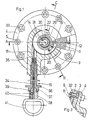
- Figur 1 eine Aufsicht auf einen teilweise aufgeschnittenen Drehantrieb,
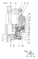
- Figur 2 einen Schnitt entlang der Linie A-B in Figur 1,
- Figur 3 einen Schnitt entlang der Linie C-D in Figur 1 und
- Figur 4 eine Einzelheit in vergrößertem Maßstab.
- Der Antrieb 1 weist gemäß Fig. 1 und 2 ein in ein Mantelteil 2, einen Zwischendeckel 3 und einen Deckel 4 aufgegliedertes Gehäuse 2, 3, 4 auf, welches mittels Schraubbolzen 5 undrehbar mit dem Gehäuse 6 eines in weiteren nicht dargestellten Federspeicherbremszylinders oder Gestängestellers verbunden ist ; im Gehäuse 7 befindet sich das durch den Drehantrieb 1 anzutreibende Teil 7. Bei Anwendung des Drehantriebes 1 an einem Federspeicherbremszylinder nach der bereits erwähnten DE-AS-24 50 652 entspricht das Gehäuse 6 dem dortigen Bremszylindergehäuse und das Teil 7 der dortigen Bedienungsmuffe.
- In einer Aussparung 8 innerhalb des Mantelteiles 2, welche einerseits durch ein ringscheibenartiges Führungsteil 9 gegen die Stirnfläche 10 des Teiles 7 und andererseits vom Zwischendeckel 3 des Gehäuses 2, 3, 4 begrenzt ist, befindet sich eine Spiralfeder 11, deren äußeres Ende mittels eines Stiftes 12 am Mantelteil 2 verankert ist ; der Stift 12 dient dabei zugleich der Halterung des Führungsteiles 9. In einer zum Deckel 4 hin offenen Ausnehmung des Zwischendeckels 3 befindet sich ein Lager 13, welches der drehbaren, aber axial unverschieblichen Lagerung einer Seiltrommel 14 dient. Mit einem den Zwischendeckel 3 in Richtung zum Deckel 4 überragenden, kleinen Abschnitt greift das Lager 13 in eine Zentriernut des Deckels 4 ein und bewirkt hierdurch dessen Zentrierung. Das innere Ende der Spiralfeder 11 ist mittels eines Stiftes 15 an der Seiltrommel 14 verankert, welche mit einem zylindrischen Ansatz 16 in die zentrischen Ausnehmung der Spiralfeder 11 eingreift. Andererseits weist die Seiltrommel 14 eine nach radial außen offene Ringnut 17 auf, in welcher ein Seil 18, welches im Ausführungsbeispiel die Seele eines Bowdenzuges 19 bildet, aufgewickelt ist. Das Ende des Seiles 18 ist mittels Madenschrauben 20 fest mit der Seiltrommel 14 verklemmt.
- In die zentrische Ausnehmung der Seiltrommel 14 ist mittels eines nichtselbsthemmenden Gewindes 21 ein hülsenartiges Kupplungsteil 22 eingeschraubt, welches in Richtung zum Teil 7 eine radial innere Axialschulter 23 der Seiltrommel 14 überragt. Ein nahe des dem Teil 7 zugewandten Endes in das Kupplungsteil 22 eingelassener Sicherungsring 24 vermag an der Axialschulter 23 zur Anlage zu gelangen und bildet zusammen mit letzterer einen Anschlag 23, 24, welcher die Relativverschiebung des Kupplungsteiles 22 zur Seiltrommel 14 in Entfernungsrichtung vom Teil 7 begrenzt. Nahe des anderen Endes ist das Kupplungsteil 22 an seinen Innenumfang mit einer im Querschnitt gerundeten Innenringnut 25 versehen, welche aus Fig. 4 besonders deutlich ersichtlich ist. An ihrer dem Teil 7 benachbarten Stirnfläche trägt das Kupplungsteil 22 einen oder über ihren Umfang gleichmäßig verteilt mehrere Axialvorsprünge 26, welche bei Axialverschiebung des Kupplungsteiles 22 in entsprechend angeordnete Axialbohrungen 27 einzurasten vermögen und welche somit zusammen mit letzteren eine axial verzahnte Kupplung 26, 27 bilden. In den vom Kupplungsteil 22 umschlossenen Raum 28 greift ein im Querschnitt etwa U-artiger Gehäuseansatz 29 des Deckels 4 ein. Im Raum zwischen dem Kupplungsteil 22 und dem Gehäuseansatz 29 befindet sich eine Schenkelfeder 30, welche den Gehäuseansatz 29 lose umfaßt und deren Enden 31 um die Schenkelenden des Gehäuseansatzes 29 herum etwa nach radial innen abgebogen sind, so daß diese Enden 31 die Schenkelenden des Gehäuseansatzes 29 lose umgreifen. Der Außenmumfang der Schenkelfeder 30 ruht mit Reibschluß in der Innenringnut 25, wie es aus Fig. 4 ersichtlich ist. Die Schenkelfededr 30 ist damit undrehbar, aber axialverschieblich am Gehäuseansatz 29 und axial unverschieblich, aber gegen Reibwiderstand drehbar am Kupplungsteil 22 gehalten, so daß das Kupplungsteil 22 am Gehäuseansatz 29 axial verschieblich und gegen Reibwiderstand drehbar gehalten ist.
- Wie aus Fig. 3 ersichtlich, ist der Zwischendeckel 3 mittels Schrauben 32 am Mantelteil 2 gehalten, der Deckel 4 ist mittels Schrauben 33, welche das Zwischenteil 3 durchsetzen, mit dem Mantelteil 2 verschraubt. (Fig. 2).
- Der Mantel 34 des Bowdenzuges 19 ist einerseits in einer tangential zur Seiltrommel 14 verlaufenden Bohrung 35 des Deckels 4 gehalten ; das Seil 18 verläuft durch diese Bohrung 35 zur Seiltrommel 14. Der Bowdenzug 19 erstreckt sich von den vorstehend beschriebenen, insgesamt als Umsetzorgan zu bezeichnenden Teil des Drehantriebes 1 zu einer gut zugänglichen Stelle des Fahrzeuges, an welcher Stelle das andere Ende des Mantels 34 mit einem Kopfteil 36 am nicht dargestellten Fahrzeug befestigt ist. Das Kopfteil 36 endet mit einer konischen Öffnung 37, in welche ein Konusansatz 38 über einen Dichtring 39 abgedichtet einzugreifen vermag. Das die Seele des Bowdenzuges 19 darstellende Seil 18 endet im Konusansatz 38 und ist dort mittels Madenschrauben 40 durch Verklemmen gehalten. Der Konusansatz 38 ist mit einem Griffring 41 verbunden, so daß durch etwa annähernd geradliniges Wegziehen des Griffringes 41 vom Kopfteil 36 das Seil 18 von der Seiltrommel 14 unter entsprechender Drehung der letzteren abgewickelt werden kann ; die Seiltrommel 14 dreht sich hierbei in Spannrichtung der Spiralfeder 11.
- Zur Montage des Drehantriebes ist bei abgenommenen Schrauben 33 der am Lager 13 geführte Deckel 4 derart zu drehen, daß das Seil 18 auf der vermittels der Spiralfeder 11 gehaltenen Seiitrommel 14 aufgewickelt wird, bis der Konusansatz 38 satt in der Öffnung 37 anliegt. Sodann ist zum Spannen der Spiralfeder 11 die Drehnung noch etwas fortzusetzen, über das nun gespannte Seil 18 wird die Seiltrommel 14 mitgedreht und spannt dabei die Spiralfeder 11. Abschließend ist der Deckel 4 durch die Schrauben 33 fest mit den restlichen Teilen des Gehäuses 2, 3, 4 zu verbinden.
- Wird zum Betätigen des Drehantriebes 1 am Griffring 41 gezogen, so wird durch Herausziehen des Seites 18.aus dem Gehäuse 2, 3, 4 die Seiltrommel 14 in Spannrichtung der Spiralfeder 11 gedreht, wie vorstehend bereits erwähnt wurde. Bei dieser Drehung der Seiltrommel 14 verschraubt sich über das Gewinde 21 das durch Reibschluß zur Schenkelfeder 30 drehbehinderte Kupplungsteil 22 gemäß Fig. 2 nach links, wobei die Axialvorsprünge 26 entweder sofort in die Axialbohrungen 27 einrasten oder vorerst auf die Stirnfläche 10 aufsetzen. Im letzteren Fall wird bei weiterer Drehung der Seiltrommel 14 das Kupplungsteil 22 mitgedreht, bis die Axialvorsprünge 26 mit den Axialbohrungen 27 fluchten und nunmehr in letztere einrasten. Die Kupplung 26, 27 wird in jedem Falle geschlossen. Da anschließend eine weitere Axialverschiebung des Kupplungsteiles 22 durch Anlage am Teil 7 ausgeschlossen ist, wird bei weiterer Drehung der Seiltrommel 14 über das Kupplungsteil 22 und die geschlossene Kupplung 26, 27 auch das Teil 7 mitgedreht. Die relativ geringe Reibung der Schenkelfeder 30 am Kupplungsteil 22 behindert diese Drehung in nur sehr geringem Maße ; diese Reibung kann so gering sein, da sie lediglich ein Verschrauben des Kupplungsteiles 22 zu Drehbeginn der Seiltrommel 14 sicherstellen muß.
- Nach erfolgter Drehung des Teiles 7 wird der Griffring 41 bis zum Eingreifen des Konusansatzes 38 in die Öffnung 37 zurückgeführt, wobei die Spiralfeder 11 die Seiltrommel 14 in Aufwickelrichtung des Seiles 18 dreht. Infolge der am Kupplungsteil 22 wirksamen Drehhinderungen durch das Teil 7 und die Reibung an der Schenkelfeder 30 folgt dabei das Kupplungsteil 22 der Drehung nicht, sondern verschraubt sich in seine in Fig. 2 dargestellte Ausgangslage zurück, bis der Anschlag 23, 24 sich durch Anlegen des Sicherungsringes 24 an die Axialschulter 23 schließt. Während der weiteren Drehung der Seiltrommel 14 zum Aufwickeln des Seiles 18 wird das Kupplungsteil 22 unter Überwinden der Reibung zur Schenkelfeder 30 mitgedreht. Sollte die vorstehend geschilderte Betätigung trotz des großen, gegebenenfalls mehrere Umdrehungen erreichenden Drehwinkels für das Teil 7 nicht genügen, so können die vorstehend geschilderten Betätigungsvorgänge bis zum Erreichen des erforderlichen Drehwinkels bzw. der erforderlichen Umdrehungszahl des Teiles 7 wiederholt werden.
- Zum Abschluß der Betätigung verspannt die Spiralfeder 11 über die Seiltrommel 14 und das Seil 18 den Konusansatz 38 in die Öffnung 38, wie es für den Ruhezustand beschrieben wurde. Der Dichtring 39 schließt in diesem Zustand ein Verschmutzen des Drehantriebes durch Eindringen von Fremdkörpern oder Feuchtigkeit in den Bowdenzug 19 und/oder die Bohrung 35 aus. Da im übrigen der Drehantrieb 1 vollständig geschlossen ist, ist er gut gegen Verschmutzen und innere Korrosion geschützt.
- In Abänderung vom dargestellten Ausführungsbeispiel kann an die Stelle des Bowdenzuges 19 ein reiner, im Fahrzeug entsprechend zu verlegender Seilzug mit dem Seil 18 treten. Bei dieser Ausführung ist es zweckmäßig, das Seil 18 an der Eintrittsstelle in den Deckel 4 abzudichten. Weiterhin ist es bei entsprechenden Einbaubedingungen möglich, unter Entfall des Bowdenzuges 19 das Kopfteil 36 unmittelbar an der Außenmündung der Bohrung 35 zu haltern.
- Falls der Drehantrieb 1 nur relativ geringe Drehmomente ausüben muß, können die Axialvorsprünge 26 und die Axialbohrung 27 entfallen, die Kupplung zwischen dem Kupplungsteil 22 und dem Teil 7 stellt dann eine durch Anlage der Stirnfläche des Kupplungsteiles 22 an der Stirnfläche 10 gebildete Reibungskupplung dar. Bei den vorstehend beschriebenen Ausführungsbeispielen des Drehantriebes 1 ist wesentlich, daß im dargestellten Ruhezustand das Teil 7 vom Kupplungsteil 22 und damit den bewegbaren Teilen des Drehantriebes 1 vollständig entkuppelt ist. Sollten, durch Funktionsteile des Federspeicherbremszylinders bzw. Gestängestellers bedingt, am Teil 7 Drehbewegungen auftreten - solche Drehbewegungen können insbesondere durch Fahrerschütterungen angeregt werden -, so können diese Drehbewegungen zu keinerlei Verstellungen des Drehantriebes führen, insbesondere kann kein übermäßiges Spannen des Seiles 18 mit hieraus evtl. resultierenden, unerwünschten Rückwirkungen auf das Teil 7 erfolgen. In umgekehrter Drehrichtung des Teiles 7 kann auch kein Lockern des Seiles 35 und damit Unwirksamwerden des Dichtringes 39 auftreten. Sollte diese vollständige Abkupplung des Teiles 7 vom Drehantrieb in dessen Ruhestellung nicht erforderlich sein, so ist es in weiterer Abänderung der beschriebenen Ausführungsbeispiele möglich, die Seiltrommel 14 über eine Freilaufkupplung unmittelbar mit einem mit dem Teil 7 fest verbundenen Teil zu verbinden, das Gewinde 21, das Kupplungsteil 22, die Schenkelfeder 30 und der Gehäuseansatz 29 können dabei entfallen.
- Der Drehantrieb 1 ist als eine an Federspeicherbremszylinder oder Gestängesteller jeweils unterschiedlicher Bauart leicht anbaubare Baueinheit ausgebildet, er ist nach geringer Anpassung auch zur nachträglichen Ausrüstung dieser Bremsgeräte geeignet. Diese vielfältigen Anwendungsmöglichkeiten eröffnen die Möglichkeit einer kostengünstigen Fertigung in größeren Stückzahlen


Claims (6)
Applications Claiming Priority (2)
| Application Number | Priority Date | Filing Date | Title |
|---|---|---|---|
| DE19843427113 DE3427113A1 (de) | 1984-07-23 | 1984-07-23 | Willkuerlich betaetigbarer drehantrieb fuer notloese- und rueckstelleinrichtung von federspeicherbremszylindern und gestaengestellern von fahrzeugbremsanlagen |
| DE3427113 | 1984-07-23 |
Publications (2)
| Publication Number | Publication Date |
|---|---|
| EP0171627A1 EP0171627A1 (de) | 1986-02-19 |
| EP0171627B1 true EP0171627B1 (de) | 1987-09-09 |
Family
ID=6241342
Family Applications (1)
| Application Number | Title | Priority Date | Filing Date |
|---|---|---|---|
| EP85108848A Expired EP0171627B1 (de) | 1984-07-23 | 1985-07-15 | Willkürlich betätigbarer Drehantrieb für Notlöse und Rückstelleinrichtungen von Federspeicherbremszylindern und Gestängestellern von Fahrzeugbremsanlagen |
Country Status (2)
| Country | Link |
|---|---|
| EP (1) | EP0171627B1 (de) |
| DE (2) | DE3427113A1 (de) |
Cited By (1)
| Publication number | Priority date | Publication date | Assignee | Title |
|---|---|---|---|---|
| DE19829437B4 (de) * | 1998-07-01 | 2009-09-17 | Knorr-Bremse Systeme für Schienenfahrzeuge GmbH | Federspeicher-Bremsvorrichtung |
Families Citing this family (3)
| Publication number | Priority date | Publication date | Assignee | Title |
|---|---|---|---|---|
| DE19724435A1 (de) * | 1997-06-10 | 1998-12-17 | Linke Hofmann Busch | Notlöseeinrichtung für Federspeicher einer Bremseinrichtung für Schienenfahrzeuge |
| DE10039161C2 (de) * | 2000-08-10 | 2002-10-24 | Knorr Bremse Systeme | Anzeigevorrichtung einer Notlöseeinrichtung an Federspeicherbremsen sowie Federspeichenbremse für Schienenfahrzeuge |
| DE102019008547B3 (de) * | 2019-12-10 | 2021-02-25 | Bundesrepublik Deutschland, vertr. durch das Bundesministerium der Verteidigung, vertr. durch das Bundesamt für Ausrüstung, Informationstechnik und Nutzung der Bundeswehr | Notlöseeinrichtung für Federspeicher-Feststellbremsen militärischer Fahrzeuge |
Family Cites Families (10)
| Publication number | Priority date | Publication date | Assignee | Title |
|---|---|---|---|---|
| DE2309757A1 (de) * | 1973-02-27 | 1974-09-12 | Segaric S A | Selbsttaetige vorrichtung zum nachstellen einer scheibenbremse |
| DE2344691C3 (de) * | 1973-09-05 | 1981-10-22 | Knorr-Bremse GmbH, 8000 München | Mechanische Lösevorrichtung für einen Federspeicherbremszylinder, insbesondere für Schienenfahrzeug-Druckluftbremsanlagen |
| GB1572812A (en) * | 1976-04-02 | 1980-08-06 | Girling Ltd | Brake actuators |
| DE2646158C2 (de) * | 1976-10-13 | 1978-12-07 | Graubremse Gmbh, 6900 Heidelberg | Schnell lösbare Federkraft-Speichervorrichtung, insbesondere für Feststellbremsen von Kraftfahrzeugen |
| SE415794B (sv) * | 1979-01-29 | 1980-10-27 | Sab Ind Ab | Anordning vid en spelrumsefterstellningsapparat |
| DE2952205A1 (de) * | 1979-12-22 | 1981-06-25 | Knorr-Bremse GmbH, 8000 München | Federspeicherbremszylinder |
| DE3007166A1 (de) * | 1980-02-26 | 1981-09-10 | Knorr-Bremse GmbH, 8000 München | Federspeicherbremszylinder |
| GB2082254B (en) * | 1980-07-17 | 1983-12-21 | Westinghouse Brake & Signal | Force actuator |
| DE3132580A1 (de) * | 1981-08-18 | 1983-03-03 | Knorr-Bremse GmbH, 8000 München | Federspeicherbremszylinder |
| IT1154433B (it) * | 1982-01-15 | 1987-01-21 | Wabco Westinghouse Spa | Attuatore a fluido sotto pressione con dispositivo di intervento a molla per freni di veicoli ferroviari e simili |
-
1984
- 1984-07-23 DE DE19843427113 patent/DE3427113A1/de not_active Withdrawn
-
1985
- 1985-07-15 EP EP85108848A patent/EP0171627B1/de not_active Expired
- 1985-07-15 DE DE8585108848T patent/DE3560562D1/de not_active Expired
Cited By (1)
| Publication number | Priority date | Publication date | Assignee | Title |
|---|---|---|---|---|
| DE19829437B4 (de) * | 1998-07-01 | 2009-09-17 | Knorr-Bremse Systeme für Schienenfahrzeuge GmbH | Federspeicher-Bremsvorrichtung |
Also Published As
| Publication number | Publication date |
|---|---|
| EP0171627A1 (de) | 1986-02-19 |
| DE3560562D1 (en) | 1987-10-15 |
| DE3427113A1 (de) | 1986-01-23 |
Similar Documents
| Publication | Publication Date | Title |
|---|---|---|
| EP0017748B1 (de) | Nachspannendes Bohrfutter | |
| DE69908866T2 (de) | Wickelvorrichtung | |
| DE2608502C3 (de) | Lösevorrichtung für die Unterbrechung und automatische Rückführung der Betriebsfunktion eines Federspeicherbremszylinders | |
| EP0271864B1 (de) | Betätigungsvorrichtung mit selbsttätiger Nachstellung für Bremsen, insbesondere von Schwerlastfahrzeugen | |
| DE4034165A1 (de) | Scheibenbremse fuer fahrzeuge | |
| EP0132601A1 (de) | Bremsgestänge für Fahrzeugreibungsbremsen | |
| DE3005420C2 (de) | ||
| DE20008414U1 (de) | Betätigungsvorrichtung | |
| DE20008415U1 (de) | Betätigungsvorrichtung | |
| DE19922333A1 (de) | Scheibenbremse mit Feststellbremsfunktion | |
| DE2129698B2 (de) | Gegen Federdruck lüftbare Reibscheibenbremse | |
| DE102020212584A1 (de) | Vorrichtung zum Betätigen einer Parksperre eines Kraftfahrzeug-Getriebes | |
| DE3533686A1 (de) | Selbsttaetige nachstelleinrichtung fuer den bremshebel einer bremse, insbesondere fuer strassenfahrzeuge | |
| EP0171627A1 (de) | Willkürlich betätigbarer Drehantrieb für Notlöse und Rückstelleinrichtungen von Federspeicherbremszylindern und Gestängestellern von Fahrzeugbremsanlagen | |
| DE3905539A1 (de) | Fernbedienbare vorrichtung zur blockierung einer spannschraube | |
| EP0499971A2 (de) | Zangenartiges Bremsgestänge, insbesondere für Scheibenbremsen von Schienenfahrzeugen | |
| DE19532590B4 (de) | Motor- und handbetätigbarer Stellantrieb | |
| DE3343268A1 (de) | Vorrichtung zur betaetigung einer feststellbremse von kraftfahrzeugen, insbesondere personenkraftwagen | |
| EP0499970B1 (de) | Zangenartiges Bremsgestänge, insbesondere für Scheibenbremsen von Schienenfahrzeugen | |
| DE3927396A1 (de) | Pneumatischer oder hydraulischer drehantrieb fuer einen absperrhahn, insbesondere kugel-absperrhahn | |
| EP0072404B1 (de) | Federspeicher-Bremszylinder | |
| DE19755210C1 (de) | Mechanische Notlösevorrichtung zur Fernbedienung für hydraulische Bremssättel | |
| DE10127463B4 (de) | Sicherheitseinrichtung für Fahrzeuge | |
| EP0319693A2 (de) | Nachstellvorrichtung für Fahrzeugbremsen | |
| DE8507264U1 (de) | Rohrleitungsarmaturenantrieb mit abschließbarer Betätigungssperre |
Legal Events
| Date | Code | Title | Description |
|---|---|---|---|
| PUAI | Public reference made under article 153(3) epc to a published international application that has entered the european phase |
Free format text: ORIGINAL CODE: 0009012 |
|
| AK | Designated contracting states |
Designated state(s): CH DE FR GB IT LI SE |
|
| 17P | Request for examination filed |
Effective date: 19851220 |
|
| 17Q | First examination report despatched |
Effective date: 19870127 |
|
| ITF | It: translation for a ep patent filed | ||
| GRAA | (expected) grant |
Free format text: ORIGINAL CODE: 0009210 |
|
| AK | Designated contracting states |
Kind code of ref document: B1 Designated state(s): CH DE FR GB IT LI SE |
|
| REF | Corresponds to: |
Ref document number: 3560562 Country of ref document: DE Date of ref document: 19871015 |
|
| ET | Fr: translation filed | ||
| PLBE | No opposition filed within time limit |
Free format text: ORIGINAL CODE: 0009261 |
|
| STAA | Information on the status of an ep patent application or granted ep patent |
Free format text: STATUS: NO OPPOSITION FILED WITHIN TIME LIMIT |
|
| 26N | No opposition filed | ||
| PGFP | Annual fee paid to national office [announced via postgrant information from national office to epo] |
Ref country code: CH Payment date: 19900529 Year of fee payment: 6 |
|
| PG25 | Lapsed in a contracting state [announced via postgrant information from national office to epo] |
Ref country code: LI Effective date: 19910731 Ref country code: CH Effective date: 19910731 |
|
| REG | Reference to a national code |
Ref country code: CH Ref legal event code: PL |
|
| ITTA | It: last paid annual fee | ||
| EAL | Se: european patent in force in sweden |
Ref document number: 85108848.4 |
|
| PGFP | Annual fee paid to national office [announced via postgrant information from national office to epo] |
Ref country code: GB Payment date: 19990628 Year of fee payment: 15 |
|
| PG25 | Lapsed in a contracting state [announced via postgrant information from national office to epo] |
Ref country code: GB Free format text: LAPSE BECAUSE OF NON-PAYMENT OF DUE FEES Effective date: 20000715 |
|
| GBPC | Gb: european patent ceased through non-payment of renewal fee |
Effective date: 20000715 |
|
| PGFP | Annual fee paid to national office [announced via postgrant information from national office to epo] |
Ref country code: FR Payment date: 20040720 Year of fee payment: 20 |
|
| PGFP | Annual fee paid to national office [announced via postgrant information from national office to epo] |
Ref country code: SE Payment date: 20040723 Year of fee payment: 20 |
|
| PGFP | Annual fee paid to national office [announced via postgrant information from national office to epo] |
Ref country code: DE Payment date: 20040921 Year of fee payment: 20 |
|
| EUG | Se: european patent has lapsed |