EP0170574B1 - Verfahren und Vorrichtung zum Steuern des Luftdurchsatzes bei einer Wärmekraftmaschine im Leerlaufzustand - Google Patents
Verfahren und Vorrichtung zum Steuern des Luftdurchsatzes bei einer Wärmekraftmaschine im Leerlaufzustand Download PDFInfo
- Publication number
- EP0170574B1 EP0170574B1 EP85401364A EP85401364A EP0170574B1 EP 0170574 B1 EP0170574 B1 EP 0170574B1 EP 85401364 A EP85401364 A EP 85401364A EP 85401364 A EP85401364 A EP 85401364A EP 0170574 B1 EP0170574 B1 EP 0170574B1
- Authority
- EP
- European Patent Office
- Prior art keywords
- speed
- engine
- air flow
- linked
- heat engine
- Prior art date
- Legal status (The legal status is an assumption and is not a legal conclusion. Google has not performed a legal analysis and makes no representation as to the accuracy of the status listed.)
- Expired
Links
- 238000000034 method Methods 0.000 title claims description 9
- 230000033228 biological regulation Effects 0.000 claims description 10
- 238000001914 filtration Methods 0.000 claims description 8
- 230000001276 controlling effect Effects 0.000 claims description 5
- 239000000446 fuel Substances 0.000 claims description 4
- 238000002347 injection Methods 0.000 claims description 4
- 239000007924 injection Substances 0.000 claims description 4
- 230000001105 regulatory effect Effects 0.000 claims description 4
- 230000010355 oscillation Effects 0.000 claims description 3
- 238000011144 upstream manufacturing Methods 0.000 claims 1
- 230000001052 transient effect Effects 0.000 description 6
- 230000010349 pulsation Effects 0.000 description 2
- 238000002485 combustion reaction Methods 0.000 description 1
- 230000001419 dependent effect Effects 0.000 description 1
- 238000010586 diagram Methods 0.000 description 1
- 210000000056 organ Anatomy 0.000 description 1
- 230000002093 peripheral effect Effects 0.000 description 1
- 230000006641 stabilisation Effects 0.000 description 1
- 238000011105 stabilization Methods 0.000 description 1
- 230000003068 static effect Effects 0.000 description 1
- 230000009466 transformation Effects 0.000 description 1
Images


Classifications
-
- F—MECHANICAL ENGINEERING; LIGHTING; HEATING; WEAPONS; BLASTING
- F02—COMBUSTION ENGINES; HOT-GAS OR COMBUSTION-PRODUCT ENGINE PLANTS
- F02D—CONTROLLING COMBUSTION ENGINES
- F02D31/00—Use of speed-sensing governors to control combustion engines, not otherwise provided for
- F02D31/001—Electric control of rotation speed
- F02D31/002—Electric control of rotation speed controlling air supply
- F02D31/003—Electric control of rotation speed controlling air supply for idle speed control
-
- F—MECHANICAL ENGINEERING; LIGHTING; HEATING; WEAPONS; BLASTING
- F02—COMBUSTION ENGINES; HOT-GAS OR COMBUSTION-PRODUCT ENGINE PLANTS
- F02D—CONTROLLING COMBUSTION ENGINES
- F02D41/00—Electrical control of supply of combustible mixture or its constituents
- F02D41/02—Circuit arrangements for generating control signals
- F02D41/14—Introducing closed-loop corrections
- F02D41/1401—Introducing closed-loop corrections characterised by the control or regulation method
- F02D2041/1413—Controller structures or design
- F02D2041/1432—Controller structures or design the system including a filter, e.g. a low pass or high pass filter
-
- F—MECHANICAL ENGINEERING; LIGHTING; HEATING; WEAPONS; BLASTING
- F02—COMBUSTION ENGINES; HOT-GAS OR COMBUSTION-PRODUCT ENGINE PLANTS
- F02D—CONTROLLING COMBUSTION ENGINES
- F02D41/00—Electrical control of supply of combustible mixture or its constituents
- F02D41/0097—Electrical control of supply of combustible mixture or its constituents using means for generating speed signals
Definitions
- the present invention relates to a method and a device for controlling the air flow rate at the intake of a heat engine powered by fuel injection in which the air flow rate is regulated as a function of the engine rotation speed. .
- the invention applies in particular to the regulation of the air flow in the vicinity of the nominal idling speed of a heat engine of a motor vehicle.
- the idle speed of a heat engine is mainly controlled by the air flow in the intake duct.
- the richness and the advance it is possible to obtain a stable speed in the absence of disturbances external to the heat engine.
- the heat engine is asked for additional power to actuate, for example, a peripheral element such as a power steering or another member, the balance of the idle is disturbed and the static adjustment of the speed cannot compensate for the variation. charge imposed.
- the action on the air flow can be carried out in different ways. This is how you can control an independent valve arranged in bypass on the main intake circuit of the engine. It is also possible to act directly on the throttle valve connected to the vehicle's accelerator control.
- the object of the present invention is to improve the operation of the regulation of the air flow at the intake, in particular during transient phenomena by providing anticipation in the control of the actuator of the regulation valve.
- the filtering is preferably carried out by a first order system analogous to a low-pass filter.
- the gain and the time constant of the first order system used for filtering are preferably chosen so that the overall transfer function brings a maximum phase advance around the maximum frequency of the motor oscillations at its idle speed.
- the regulation of the air flow at the intake in a heat engine requires a suitably controlled action on the air admitted in the heat engine.
- To carry out a suitable regulation in the case of a transient phenomenon it is not enough to open the valve below the idling speed, that is to say below the nominal idling speed of the heat engine. , because the action on the intake air would then take place too late to compensate for a rapid drop in engine speed, possibly resulting in an abrupt stop of the engine.
- FIG 1 there is shown by way of example very schematically a control valve 1 capable of acting on the air admitted into a heat engine not shown.
- the valve control signal, referenced V comes from a servo system referenced 2 as a whole, carrying out from the input signal s, a cor proportional correction by member 3 and full correction by member 4.
- the input s of the controlled system 2 would be constituted by the difference between a quantity P linked to the instantaneous value of the speed of rotation of the heat engine and a quantity R linked to the idle speed or nominal speed of rotation of the engine at idle, this value being predetermined for a given engine.
- this difference e PR, is first of all subjected to a transformation in the regulator 5.
- the control of the valve 1 is not carried out by directly taking as a reference value the desired constant idle speed linked to the quantity R, but on the contrary, from a fictitious variable reference speed and dependent on the instantaneous speed.
- the regulator according to the invention comprises a first branch 6 provided with a member 7 behaving like a first order system and with a proportional member 8.
- the instantaneous engine speed is represented by the value of the instantaneous period P.
- the idle speed which is a constant, is represented by the idle period R.
- a filtering of the instantaneous period P is carried out so as to obtain a filtered value P '.
- This filtering is carried out by the first order system 7 whose input P is linked to the output P 'by the first degree differential equation:
- the input of the filter 7 is the difference P-R. Due to the fact that the idle period R is constant, the output of the filter 7 is therefore P'-R.
- the setpoint value chosen for the control of the control valve 1 is a setpoint period C which is constituted by the weighted average between the filtered value of the instantaneous period P 'and the idle period R.
- This setpoint is therefore chosen by definition as follows:
- the signal e at the input of the regulator 5 is subjected in a first branch to a first filtering 7 supplying the filtered signal e 'which is then subjected to a proportional member 8 of coefficient K.
- the same input signal e is subjected in the second branch 9 of the regulator 5 to the faction of a proportional member 10 of coefficient 1.
- the output of the first branch 6 is subtracted from the output of the second branch 9 so as to provide the output signal s.
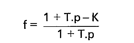
- the transfer function of the servo 2 placed downstream and in series of the regulator 5 is of the form: where Kp is the coefficient of the proportional member 3, while K is the coefficient of the integral member 4.
- Kp is the coefficient of the proportional member 3
- K is the coefficient of the integral member 4.
- FIG. 2 the values of the instantaneous rotational speeds N of a heat engine are shown on the ordinate, that is to say the inverse values of the periods P and on the abscissa the time t.
- the air intake control valve would be open at time t 2 when the instantaneous speed N becomes equal to the constant and predetermined idling speed N R (intersection B of the curves N and N R ).
- the instantaneous regime N is filtered so as to obtain a variable filtered regime N 'whose evolution is represented on the curve of FIG. 2 referenced N'.
- the filtered value is further transformed by carrying out the weighted average which has been explained previously so as to obtain a reference value for the engine speed, the evolution of which is represented by the curve referenced Ne. It is this setpoint which is used as input to the slave system.
- the action on the control valve occurs at time t l , that is to say at mo ment where the difference between the nominal value Ne and the instantaneous value N is zero, at point A.
- the invention therefore makes it possible to anticipate the action on the valve control, thus preventing the engine from suddenly stopping in the event of a rapid fall in the instantaneous speed of the heat engine.
- the input signal consists of the difference between the instantaneous speed (N or P) and the idle speed (N R or R) while according to the invention, the setpoint is constituted by the output s of regulator 5, that is to say the difference between the setpoint speed Ne or its period C and the idle speed (N R or R).
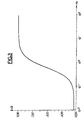
- FIG. 3 represents the variations of the module or ratio of amplitudes of the output signal to the input signal expressed in decibels as a function of the pulsation expressed in Hertz and represented on a logarithmic scale: If one wishes to attenuate the decrease in gain in the vicinity of low frequencies, it is possible to act on the characteristics of the servo 2, for example by an increase in the integral term K.
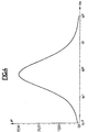
- FIG. 4 represents the variations of the phase expressed in degrees as a function of the pulsation expressed in Hertz on a logarithmic scale.
- the regulator of the invention provides a phase advance with a maximum which is around 0.7 to 0.8 Hz.
- the maximum phase advance is around the maximum frequency of the motor oscillations at its idling speed which is generally of the order of 0.5 to 1 Hz.
- the addition of the regulator of the invention makes it possible to act on the servo-control and for example to open the valve for controlling the admission of air into the heat engine in transient mode, for example in the case of '' a no-load deceleration before the engine speed is lower than the idle speed.
Landscapes
- Engineering & Computer Science (AREA)
- Chemical & Material Sciences (AREA)
- Combustion & Propulsion (AREA)
- Mechanical Engineering (AREA)
- General Engineering & Computer Science (AREA)
- Electrical Control Of Air Or Fuel Supplied To Internal-Combustion Engine (AREA)
- Combined Controls Of Internal Combustion Engines (AREA)
- Preparation Of Compounds By Using Micro-Organisms (AREA)
Claims (5)

Applications Claiming Priority (2)
| Application Number | Priority Date | Filing Date | Title |
|---|---|---|---|
| FR8411667A FR2567961B1 (fr) | 1984-07-23 | 1984-07-23 | Procede et dispositif de commande du debit d'air d'un moteur thermique au ralenti |
| FR8411667 | 1984-07-23 |
Publications (2)
| Publication Number | Publication Date |
|---|---|
| EP0170574A1 EP0170574A1 (de) | 1986-02-05 |
| EP0170574B1 true EP0170574B1 (de) | 1988-09-14 |
Family
ID=9306394
Family Applications (1)
| Application Number | Title | Priority Date | Filing Date |
|---|---|---|---|
| EP85401364A Expired EP0170574B1 (de) | 1984-07-23 | 1985-07-05 | Verfahren und Vorrichtung zum Steuern des Luftdurchsatzes bei einer Wärmekraftmaschine im Leerlaufzustand |
Country Status (6)
| Country | Link |
|---|---|
| US (1) | US4658782A (de) |
| EP (1) | EP0170574B1 (de) |
| JP (1) | JPH0759906B2 (de) |
| CA (1) | CA1252544A (de) |
| DE (1) | DE3564983D1 (de) |
| FR (1) | FR2567961B1 (de) |
Families Citing this family (3)
| Publication number | Priority date | Publication date | Assignee | Title |
|---|---|---|---|---|
| JPS62240442A (ja) * | 1986-04-09 | 1987-10-21 | Hitachi Ltd | 燃料制御装置 |
| JP3876609B2 (ja) * | 2000-10-31 | 2007-02-07 | トヨタ自動車株式会社 | 内燃機関のアイドル回転制御装置 |
| DE10221681B4 (de) * | 2002-05-16 | 2005-12-08 | Mtu Friedrichshafen Gmbh | Verfahren zur Regelung einer Brennkraftmaschinen-Generator-Einheit |
Family Cites Families (15)
| Publication number | Priority date | Publication date | Assignee | Title |
|---|---|---|---|---|
| NL7012597A (de) * | 1970-08-25 | 1972-02-29 | ||
| JPS6060025B2 (ja) * | 1977-10-19 | 1985-12-27 | 株式会社日立製作所 | 自動車制御方法 |
| DE2906782A1 (de) * | 1979-02-22 | 1980-09-04 | Bosch Gmbh Robert | Einrichtung zum daempfen von ruckelschwingungen bei einer brennkraftmaschine |
| GB2051420B (en) * | 1979-04-24 | 1983-12-14 | Nissan Motor | Intake air flow control system to control idling speed of an internal combustion engine |
| FR2462562A1 (fr) * | 1979-07-26 | 1981-02-13 | Motobecane Ateliers | Procede et dispositif pour la regulation automatique du regime d'un moteur a combustion interne |
| JPS56132430A (en) * | 1980-03-24 | 1981-10-16 | Hitachi Ltd | Idling rotary speed controller |
| US4307690A (en) * | 1980-06-05 | 1981-12-29 | Rockwell International Corporation | Electronic, variable speed engine governor |
| JPS5759038A (en) * | 1980-09-25 | 1982-04-09 | Toyota Motor Corp | Intake air flow controlling process in internal combustion engine |
| DE3039435C2 (de) * | 1980-10-18 | 1984-03-22 | Robert Bosch Gmbh, 7000 Stuttgart | Vorrichtung zur Regelung der Leerlauf-Drehzahl von Brennkraftmaschinen |
| US4401075A (en) * | 1980-10-27 | 1983-08-30 | The Bendix Corporation | Automatic speed control for heavy vehicles |
| JPS58187556A (ja) * | 1982-04-28 | 1983-11-01 | Nippon Denso Co Ltd | 内燃機関制御用信号処理装置 |
| DE3232725A1 (de) * | 1982-09-03 | 1984-03-08 | Robert Bosch Gmbh, 7000 Stuttgart | Regeleinrichtung fuer ein stellwerk bei einer brennkraftmaschine mit selbstzuendung |
| DE3246524A1 (de) * | 1982-12-16 | 1984-06-20 | Robert Bosch Gmbh, 7000 Stuttgart | Drehzahlregelsystem fuer eine brennkraftmaschine |
| FR2538855B1 (fr) * | 1982-12-30 | 1987-05-15 | Renault | Procede de stabilisation de la vitesse de rotation a vide d'un moteur a allumage commande |
| JPS606071A (ja) * | 1983-06-24 | 1985-01-12 | Toyota Motor Corp | 車両用エンジンの点火時期制御装置 |
-
1984
- 1984-07-23 FR FR8411667A patent/FR2567961B1/fr not_active Expired
-
1985
- 1985-07-05 EP EP85401364A patent/EP0170574B1/de not_active Expired
- 1985-07-05 DE DE8585401364T patent/DE3564983D1/de not_active Expired
- 1985-07-22 US US06/757,298 patent/US4658782A/en not_active Expired - Lifetime
- 1985-07-22 CA CA000487208A patent/CA1252544A/fr not_active Expired
- 1985-07-23 JP JP60161347A patent/JPH0759906B2/ja not_active Expired - Lifetime
Also Published As
| Publication number | Publication date |
|---|---|
| EP0170574A1 (de) | 1986-02-05 |
| CA1252544A (fr) | 1989-04-11 |
| DE3564983D1 (en) | 1988-10-20 |
| FR2567961A1 (fr) | 1986-01-24 |
| FR2567961B1 (fr) | 1986-12-12 |
| JPH0759906B2 (ja) | 1995-06-28 |
| US4658782A (en) | 1987-04-21 |
| JPS61135955A (ja) | 1986-06-23 |
Similar Documents
| Publication | Publication Date | Title |
|---|---|---|
| US3661131A (en) | Speed controls | |
| FR2464852A1 (fr) | Dispositif de commande pour un mecanisme de reglage en continu, de conformation en carburant d'un moteur a combustion d'automobile | |
| FR2460391A1 (fr) | Circuit de reglage du debit de carburant d'un moteur a turbine a gaz | |
| FR2771450A1 (fr) | Commande de la pression d'alimentation d'un moteur a combustion interne suralimente et utilisation de cette commande | |
| CA1048623A (en) | Engine speed limiting control circuit | |
| FR2579145A1 (fr) | Dispositif pour influencer la vitesse de deplacement d'un vehicule automobile | |
| FR2467294A1 (fr) | Systeme de commande d'injection de carburant | |
| FR2736010A1 (fr) | Procede et dispositif pour commander l'unite d'entrainement d'un vehicule a moteur | |
| FR2714697A1 (fr) | Système de régulation de la suralimentation d'un moteur à combustion interne. | |
| FR2556293A1 (fr) | Procede de reglage de la vitesse d'un vehicule a moteur et installation pour sa mise en oeuvre | |
| FR2568942A1 (fr) | Systeme de regulation de la vitesse de rotation de moteurs a combustion interne | |
| EP0170574A1 (de) | Verfahren und Vorrichtung zum Steuern des Luftdurchsatzes bei einer Wärmekraftmaschine im Leerlaufzustand | |
| FR2579672A1 (fr) | Dispositif de controle du nombre de tours par minute d'un moteur a combustion interne | |
| FR2716417A1 (fr) | Procédé et dispositif pour régler le régime d'un groupe d'entraînement d'un véhicule au ralenti. | |
| FR2754310A1 (fr) | Groupe motopropulseur pour avion et son procede de commande | |
| FR2645591A1 (fr) | Procede et dispositif pour le fonctionnement d'une unite motrice notamment des excavatrices ou analogues | |
| FR2861860A1 (fr) | Procede de gestion d'une unite d'entrainement | |
| FR2574127A1 (fr) | Methode de reglage d'un rapport air/combustible pour un moteur a combustion interne | |
| EP1753947B1 (de) | Verfahren zur steuerung eines eingestellten drehmoments für räder eines automatikgetriebes für ein kraftfahrzeug und entsprechende vorrichtung | |
| FR2818313A1 (fr) | Procede pour la regulation d'un dispositif de chargement pour un moteur a combustion interne | |
| EP0856099B1 (de) | System und verfahren mit einem doppelten regelungskreis für brennkraftmaschine | |
| FR2724881A1 (fr) | Dispositif d'entrainement des accessoires d'un moteur a combustion de vehicule automobile | |
| EP0884466A1 (de) | Verfahren und Vorrichtung zum Korrigieren des Luft/Kraftstoff-Verhältnisses in einer Brennkraftmaschine | |
| FR2851298A1 (fr) | Procede de commande d'un moteur thermique, appareil de commande et/ou de regulation pour un moteur thermique, programme d'ordinateur et support de memoire electrique d'un moteur thermique | |
| JPS59110847A (ja) | 内燃機関の回転数制御装置 |
Legal Events
| Date | Code | Title | Description |
|---|---|---|---|
| PUAI | Public reference made under article 153(3) epc to a published international application that has entered the european phase |
Free format text: ORIGINAL CODE: 0009012 |
|
| 17P | Request for examination filed |
Effective date: 19850710 |
|
| AK | Designated contracting states |
Designated state(s): CH DE GB IT LI NL SE |
|
| 17Q | First examination report despatched |
Effective date: 19870325 |
|
| GRAA | (expected) grant |
Free format text: ORIGINAL CODE: 0009210 |
|
| AK | Designated contracting states |
Kind code of ref document: B1 Designated state(s): CH DE GB IT LI NL SE |
|
| ITF | It: translation for a ep patent filed | ||
| GBT | Gb: translation of ep patent filed (gb section 77(6)(a)/1977) | ||
| REF | Corresponds to: |
Ref document number: 3564983 Country of ref document: DE Date of ref document: 19881020 |
|
| PLBE | No opposition filed within time limit |
Free format text: ORIGINAL CODE: 0009261 |
|
| STAA | Information on the status of an ep patent application or granted ep patent |
Free format text: STATUS: NO OPPOSITION FILED WITHIN TIME LIMIT |
|
| 26N | No opposition filed | ||
| ITTA | It: last paid annual fee | ||
| EAL | Se: european patent in force in sweden |
Ref document number: 85401364.6 |
|
| PGFP | Annual fee paid to national office [announced via postgrant information from national office to epo] |
Ref country code: GB Payment date: 19990614 Year of fee payment: 15 |
|
| PGFP | Annual fee paid to national office [announced via postgrant information from national office to epo] |
Ref country code: CH Payment date: 19990617 Year of fee payment: 15 |
|
| PGFP | Annual fee paid to national office [announced via postgrant information from national office to epo] |
Ref country code: SE Payment date: 19990622 Year of fee payment: 15 |
|
| PGFP | Annual fee paid to national office [announced via postgrant information from national office to epo] |
Ref country code: NL Payment date: 19990624 Year of fee payment: 15 |
|
| PG25 | Lapsed in a contracting state [announced via postgrant information from national office to epo] |
Ref country code: GB Free format text: LAPSE BECAUSE OF NON-PAYMENT OF DUE FEES Effective date: 20000705 |
|
| PG25 | Lapsed in a contracting state [announced via postgrant information from national office to epo] |
Ref country code: SE Free format text: LAPSE BECAUSE OF NON-PAYMENT OF DUE FEES Effective date: 20000706 |
|
| PG25 | Lapsed in a contracting state [announced via postgrant information from national office to epo] |
Ref country code: LI Free format text: LAPSE BECAUSE OF NON-PAYMENT OF DUE FEES Effective date: 20000731 Ref country code: CH Free format text: LAPSE BECAUSE OF NON-PAYMENT OF DUE FEES Effective date: 20000731 |
|
| PG25 | Lapsed in a contracting state [announced via postgrant information from national office to epo] |
Ref country code: NL Free format text: LAPSE BECAUSE OF NON-PAYMENT OF DUE FEES Effective date: 20010201 |
|
| GBPC | Gb: european patent ceased through non-payment of renewal fee |
Effective date: 20000705 |
|
| REG | Reference to a national code |
Ref country code: CH Ref legal event code: PL |
|
| EUG | Se: european patent has lapsed |
Ref document number: 85401364.6 |
|
| NLV4 | Nl: lapsed or anulled due to non-payment of the annual fee |
Effective date: 20010201 |
|
| PGFP | Annual fee paid to national office [announced via postgrant information from national office to epo] |
Ref country code: DE Payment date: 20040706 Year of fee payment: 20 |