EP0170574B1 - Method and apparatus for controlling the intake air flow in a thermal engine during idling - Google Patents
Method and apparatus for controlling the intake air flow in a thermal engine during idling Download PDFInfo
- Publication number
- EP0170574B1 EP0170574B1 EP85401364A EP85401364A EP0170574B1 EP 0170574 B1 EP0170574 B1 EP 0170574B1 EP 85401364 A EP85401364 A EP 85401364A EP 85401364 A EP85401364 A EP 85401364A EP 0170574 B1 EP0170574 B1 EP 0170574B1
- Authority
- EP
- European Patent Office
- Prior art keywords
- speed
- engine
- air flow
- linked
- heat engine
- Prior art date
- Legal status (The legal status is an assumption and is not a legal conclusion. Google has not performed a legal analysis and makes no representation as to the accuracy of the status listed.)
- Expired
Links
Images


Classifications
-
- F—MECHANICAL ENGINEERING; LIGHTING; HEATING; WEAPONS; BLASTING
- F02—COMBUSTION ENGINES; HOT-GAS OR COMBUSTION-PRODUCT ENGINE PLANTS
- F02D—CONTROLLING COMBUSTION ENGINES
- F02D31/00—Use of speed-sensing governors to control combustion engines, not otherwise provided for
- F02D31/001—Electric control of rotation speed
- F02D31/002—Electric control of rotation speed controlling air supply
- F02D31/003—Electric control of rotation speed controlling air supply for idle speed control
-
- F—MECHANICAL ENGINEERING; LIGHTING; HEATING; WEAPONS; BLASTING
- F02—COMBUSTION ENGINES; HOT-GAS OR COMBUSTION-PRODUCT ENGINE PLANTS
- F02D—CONTROLLING COMBUSTION ENGINES
- F02D41/00—Electrical control of supply of combustible mixture or its constituents
- F02D41/02—Circuit arrangements for generating control signals
- F02D41/14—Introducing closed-loop corrections
- F02D41/1401—Introducing closed-loop corrections characterised by the control or regulation method
- F02D2041/1413—Controller structures or design
- F02D2041/1432—Controller structures or design the system including a filter, e.g. a low pass or high pass filter
-
- F—MECHANICAL ENGINEERING; LIGHTING; HEATING; WEAPONS; BLASTING
- F02—COMBUSTION ENGINES; HOT-GAS OR COMBUSTION-PRODUCT ENGINE PLANTS
- F02D—CONTROLLING COMBUSTION ENGINES
- F02D41/00—Electrical control of supply of combustible mixture or its constituents
- F02D41/0097—Electrical control of supply of combustible mixture or its constituents using means for generating speed signals
Definitions
- the present invention relates to a method and a device for controlling the air flow rate at the intake of a heat engine powered by fuel injection in which the air flow rate is regulated as a function of the engine rotation speed. .
- the invention applies in particular to the regulation of the air flow in the vicinity of the nominal idling speed of a heat engine of a motor vehicle.
- the idle speed of a heat engine is mainly controlled by the air flow in the intake duct.
- the richness and the advance it is possible to obtain a stable speed in the absence of disturbances external to the heat engine.
- the heat engine is asked for additional power to actuate, for example, a peripheral element such as a power steering or another member, the balance of the idle is disturbed and the static adjustment of the speed cannot compensate for the variation. charge imposed.
- the action on the air flow can be carried out in different ways. This is how you can control an independent valve arranged in bypass on the main intake circuit of the engine. It is also possible to act directly on the throttle valve connected to the vehicle's accelerator control.
- the object of the present invention is to improve the operation of the regulation of the air flow at the intake, in particular during transient phenomena by providing anticipation in the control of the actuator of the regulation valve.
- the filtering is preferably carried out by a first order system analogous to a low-pass filter.
- the gain and the time constant of the first order system used for filtering are preferably chosen so that the overall transfer function brings a maximum phase advance around the maximum frequency of the motor oscillations at its idle speed.
- the regulation of the air flow at the intake in a heat engine requires a suitably controlled action on the air admitted in the heat engine.
- To carry out a suitable regulation in the case of a transient phenomenon it is not enough to open the valve below the idling speed, that is to say below the nominal idling speed of the heat engine. , because the action on the intake air would then take place too late to compensate for a rapid drop in engine speed, possibly resulting in an abrupt stop of the engine.
- FIG 1 there is shown by way of example very schematically a control valve 1 capable of acting on the air admitted into a heat engine not shown.
- the valve control signal, referenced V comes from a servo system referenced 2 as a whole, carrying out from the input signal s, a cor proportional correction by member 3 and full correction by member 4.
- the input s of the controlled system 2 would be constituted by the difference between a quantity P linked to the instantaneous value of the speed of rotation of the heat engine and a quantity R linked to the idle speed or nominal speed of rotation of the engine at idle, this value being predetermined for a given engine.
- this difference e PR, is first of all subjected to a transformation in the regulator 5.
- the control of the valve 1 is not carried out by directly taking as a reference value the desired constant idle speed linked to the quantity R, but on the contrary, from a fictitious variable reference speed and dependent on the instantaneous speed.
- the regulator according to the invention comprises a first branch 6 provided with a member 7 behaving like a first order system and with a proportional member 8.
- the instantaneous engine speed is represented by the value of the instantaneous period P.
- the idle speed which is a constant, is represented by the idle period R.
- a filtering of the instantaneous period P is carried out so as to obtain a filtered value P '.
- This filtering is carried out by the first order system 7 whose input P is linked to the output P 'by the first degree differential equation:
- the input of the filter 7 is the difference P-R. Due to the fact that the idle period R is constant, the output of the filter 7 is therefore P'-R.
- the setpoint value chosen for the control of the control valve 1 is a setpoint period C which is constituted by the weighted average between the filtered value of the instantaneous period P 'and the idle period R.
- This setpoint is therefore chosen by definition as follows:
- the signal e at the input of the regulator 5 is subjected in a first branch to a first filtering 7 supplying the filtered signal e 'which is then subjected to a proportional member 8 of coefficient K.
- the same input signal e is subjected in the second branch 9 of the regulator 5 to the faction of a proportional member 10 of coefficient 1.
- the output of the first branch 6 is subtracted from the output of the second branch 9 so as to provide the output signal s.
- the transfer function of the servo 2 placed downstream and in series of the regulator 5 is of the form: where Kp is the coefficient of the proportional member 3, while K is the coefficient of the integral member 4.
- Kp is the coefficient of the proportional member 3
- K is the coefficient of the integral member 4.
- FIG. 2 the values of the instantaneous rotational speeds N of a heat engine are shown on the ordinate, that is to say the inverse values of the periods P and on the abscissa the time t.
- the air intake control valve would be open at time t 2 when the instantaneous speed N becomes equal to the constant and predetermined idling speed N R (intersection B of the curves N and N R ).
- the instantaneous regime N is filtered so as to obtain a variable filtered regime N 'whose evolution is represented on the curve of FIG. 2 referenced N'.
- the filtered value is further transformed by carrying out the weighted average which has been explained previously so as to obtain a reference value for the engine speed, the evolution of which is represented by the curve referenced Ne. It is this setpoint which is used as input to the slave system.
- the action on the control valve occurs at time t l , that is to say at mo ment where the difference between the nominal value Ne and the instantaneous value N is zero, at point A.
- the invention therefore makes it possible to anticipate the action on the valve control, thus preventing the engine from suddenly stopping in the event of a rapid fall in the instantaneous speed of the heat engine.
- the input signal consists of the difference between the instantaneous speed (N or P) and the idle speed (N R or R) while according to the invention, the setpoint is constituted by the output s of regulator 5, that is to say the difference between the setpoint speed Ne or its period C and the idle speed (N R or R).
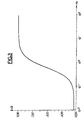
- FIG. 3 represents the variations of the module or ratio of amplitudes of the output signal to the input signal expressed in decibels as a function of the pulsation expressed in Hertz and represented on a logarithmic scale: If one wishes to attenuate the decrease in gain in the vicinity of low frequencies, it is possible to act on the characteristics of the servo 2, for example by an increase in the integral term K.
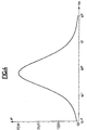
- FIG. 4 represents the variations of the phase expressed in degrees as a function of the pulsation expressed in Hertz on a logarithmic scale.
- the regulator of the invention provides a phase advance with a maximum which is around 0.7 to 0.8 Hz.
- the maximum phase advance is around the maximum frequency of the motor oscillations at its idling speed which is generally of the order of 0.5 to 1 Hz.
- the addition of the regulator of the invention makes it possible to act on the servo-control and for example to open the valve for controlling the admission of air into the heat engine in transient mode, for example in the case of '' a no-load deceleration before the engine speed is lower than the idle speed.
Description
La présente invention a pour objet un procédé et un dispositif de commande du débit d'air à l'admission d'un moteur thermique alimenté par injection de carburant dans lequel le débit d'air est régulé en fonction de la vitesse de rotation du moteur. L'invention s'applique en particulier à la régulation du débit d'air au voisinage de la vitesse nominale de rotation au ralenti d'un moteur thermique de véhicule automobile.The present invention relates to a method and a device for controlling the air flow rate at the intake of a heat engine powered by fuel injection in which the air flow rate is regulated as a function of the engine rotation speed. . The invention applies in particular to the regulation of the air flow in the vicinity of the nominal idling speed of a heat engine of a motor vehicle.
On sait que le régime de ralenti d'un moteur thermique est principalement réglé par le débit d'air dans le conduit d'admission. En réglant correctement la richesse et l'avance, on parvient à obtenir un régime stable en l'absence de perturbations extérieures au moteur thermique. Par contre, lorsqu'on demande au moteur thermique une puissance supplémentaire pour actionner par exemple un élément périphérique tel qu'une direction assistée ou un autre organe, l'équilibre du ralenti se trouve perturbé et le réglage statique du régime ne peut compenser la variation de charge imposée.We know that the idle speed of a heat engine is mainly controlled by the air flow in the intake duct. By correctly adjusting the richness and the advance, it is possible to obtain a stable speed in the absence of disturbances external to the heat engine. On the other hand, when the heat engine is asked for additional power to actuate, for example, a peripheral element such as a power steering or another member, the balance of the idle is disturbed and the static adjustment of the speed cannot compensate for the variation. charge imposed.
On a déjà prévu pour rétablir alors le régime de ralenti d'un tel moteur thermique d'utiliser un actionneur capable de modifier le débit d'air dans la conduite d'admission. La commande de cet actionneur permet de conserver un régime de ralenti indépendant des conditions extérieures du moteur thermique et d'obtenir un ralenti plus stable en compensant les petites variations inévitables sur un moteur.It has already been planned to re-establish the idle speed of such a heat engine to use an actuator capable of modifying the air flow in the intake pipe. The control of this actuator makes it possible to maintain an idling speed independent of the external conditions of the heat engine and to obtain a more stable idling speed by compensating for the inevitable small variations on an engine.
L'action sur le débit d'air peut être réalisée de différentes manières. C'est ainsi que l'on peut commander une vanne indépendante disposée en by-pass sur le circuit d'admission principal du moteur. On peut également agir directement sur le papillon relié à la commande d'accélérateur du véhicule.The action on the air flow can be carried out in different ways. This is how you can control an independent valve arranged in bypass on the main intake circuit of the engine. It is also possible to act directly on the throttle valve connected to the vehicle's accelerator control.
Dans les dispositifs connus de ce type, la commande de l'actionneur peut donc être assimilée à un asservissement du débit d'air à l'admission au régime moteur ou vitesse de rotation du moteur thermique. Le document GB-A-2 085 619 décrit un procédé de régulation de la vitesse de ralenti d'un moteur thermique dans lequel un actionneur est commandé pour réguler le débit d'air du ralenti, cette commande étant assurée par un système asservi recevant en entrée l'écart entre la vitesse de rotation du moteur et une valeur de consigne. On constate cependant dans la pratique des difficultés d'application, en particulier lors des phénomènes transitoires. Il est en effet difficile pour les régulations de type classique d'effectuer une différence entre une action de stabilisation du ralenti et les phénomènes transitoires mal définis pouvant exister dans un moteur thermique. Il en est ainsi en particulier lors d'une décélération rapide du moteur thermique qui peut entraîner un sous-régime trop important du moteur ou même un calage complet avec arrêt du moteur.In known devices of this type, the control of the actuator can therefore be assimilated to a servo-control of the air flow rate on admission to the engine speed or rotation speed of the heat engine. Document GB-A-2 085 619 describes a method for regulating the idle speed of a heat engine in which an actuator is controlled to regulate the air flow of the idle, this control being ensured by a servo system receiving in input the difference between the motor speed and a setpoint. However, in practice there are application difficulties, in particular during transient phenomena. It is indeed difficult for conventional type regulations to make a difference between an idle stabilization action and ill-defined transient phenomena that may exist in a heat engine. This is particularly the case during a rapid deceleration of the heat engine which can cause an excessive sub-regime of the engine or even a complete stall with engine stopping.
La présente invention a pour objet d'améliorer le fonctionnement de la régulation du débit d'air à l'admission, en particulier lors des phénomènes transitoires en apportant une anticipation dans la commande de l'actionneur de la vanne de régulation.The object of the present invention is to improve the operation of the regulation of the air flow at the intake, in particular during transient phenomena by providing anticipation in the control of the actuator of the regulation valve.
Le procédé de commande du débit d'air à l'admission d'un moteur thermique alimenté par injection de carburant, selon l'invention, dans lequel le débit d'air est régulé en fonction de la vitesse de rotation du moteur au voisinage de sa vitesse nominale de ralenti, consiste à prendre comme valeur de consigne C de la régulation, le résultat d'un filtrage effectué sur une grandeur P liée à la valeur instantanée de la vitesse de rotation du moteur thermique suivi d'une moyenne pondérée entre la valeur filtrée P' ainsi obtenue et une grandeur R liée à la vitesse nominale de ralenti, de sorte que C=KP'+(1-K) R.The method of controlling the air flow at the intake of a combustion engine powered by fuel injection, according to the invention, in which the air flow is regulated as a function of the speed of rotation of the engine in the vicinity of its nominal idling speed, consists in taking as the reference value C of the regulation, the result of a filtering carried out on a quantity P linked to the instantaneous value of the speed of rotation of the thermal engine followed by a weighted average between the filtered value P 'thus obtained and a quantity R linked to the nominal idling speed, so that C = KP' + (1-K) R.
Le filtrage est de préférence effectué par un système du premier ordre analogue à un filtre passe-bas.The filtering is preferably carried out by a first order system analogous to a low-pass filter.
Le gain et la constante de temps du système du premier ordre utilisé pour le filtrage sont de préférence choisis de façon que la fonction de transfert globale apporte une avance de phase maximale aux alentours de la fréquence maximale des oscillations du moteur à sa vitesse de ralenti.The gain and the time constant of the first order system used for filtering are preferably chosen so that the overall transfer function brings a maximum phase advance around the maximum frequency of the motor oscillations at its idle speed.
L'invention sera mieux comprise à l'étude de la description détaillée d'un exemple de réalisation décrit à titre nullement limitatif et illustré par les dessins annexés, sur lesquels:
- - la figure 1 est un schéma fonctionnel des principaux éléments d'un système asservi comprenant le régulateur de l'invention;
- - la figure 2 illustre certaines courbes permettant de comprendre le fonctionnement de l'invention;
- - et les figures 3 et 4 représentent respectivement le module et la phase de la fonction de transfert d'un exemple de réalisation du régulateur utilisé dans la présente invention.
- - Figure 1 is a block diagram of the main elements of a slave system comprising the regulator of the invention;
- - Figure 2 illustrates some curves for understanding the operation of the invention;
- - And Figures 3 and 4 respectively represent the module and the phase of the transfer function of an embodiment of the regulator used in the present invention.
La régulation du débit d'air à l'admission dans un moteur thermique nécessite une action convenablement asservie sur l'air admis dans le moteur thermique. Dans le cas d'une régulation au moyen d'une vanne, il s'agit donc d'ouvrir cette vanne lorsque le régime ou vitesse de rotation du moteur thermique est trop faible et au contraire de la fermer lorsque le régime ou vitesse de rotation du moteur thermique est trop élevé. Pour effectuer une régulation convenable dans le cas d'un phénomène transitoire, il ne suffit pas d'ouvrir la vanne au-dessous du régime de ralenti, c'est-à-dire au-dessous de la vitesse nominale de ralenti du moteur thermique, car l'action sur l'air à l'admission interviendrait alors trop tard pour compenser une chute rapide de régime du moteur thermique entraînant éventuellement un arrêt brusque du moteur.The regulation of the air flow at the intake in a heat engine requires a suitably controlled action on the air admitted in the heat engine. In the case of regulation by means of a valve, it is therefore a question of opening this valve when the speed or speed of rotation of the thermal engine is too low and on the contrary of closing it when the speed or speed of rotation of the engine is too high. To carry out a suitable regulation in the case of a transient phenomenon, it is not enough to open the valve below the idling speed, that is to say below the nominal idling speed of the heat engine. , because the action on the intake air would then take place too late to compensate for a rapid drop in engine speed, possibly resulting in an abrupt stop of the engine.
Sur la figure 1 on a représenté à titre d'exemple de façon très schématique une vanne de commande 1 capable d'agir sur l'air admis dans un moteur thermique non représenté. Le signal de commande de la vanne, référencé V, est issu d'un système asservi référencé 2 dans son ensemble, effectuant à partir du signal d'entrée s, une correction proportionnelle par l'organe 3 et une correction intégrale par l'organe 4.In Figure 1 there is shown by way of example very schematically a
Dans un système classique, l'entréé s du système asservi 2 serait constituée par l'écart entre une grandeur P liée à la valeur instantanée de la vitesse de rotation du moteur thermique et une grandeur R liée au régime de ralenti ou vitesse de rotation nominale du moteur thermique au ralenti, cette valeur étant prédéterminée pour un moteur thermique donné.In a conventional system, the input s of the controlled system 2 would be constituted by the difference between a quantity P linked to the instantaneous value of the speed of rotation of the heat engine and a quantity R linked to the idle speed or nominal speed of rotation of the engine at idle, this value being predetermined for a given engine.
Selon l'invention, cet écart e=P-R, est tout d'abord soumis à une transformation dans le régulateur 5. En d'autres termes, la commande de la vanne 1 n'est pas réalisée en prenant directement comme valeur de consigne le régime de ralenti constant souhaité lié à la grandeur R, mais au contraire, à partir d'un régime de consigne fictif variable et dépendant du régime instantané.According to the invention, this difference e = PR, is first of all subjected to a transformation in the
Le régulateur selon l'invention comprend une première branche 6 munie d'un organe 7 se comportant comme un système du premier ordre et d'un organe 8 proportionnel.The regulator according to the invention comprises a
On va maintenant, à titre d'exemple, préciser l'action des différents organes du système de l'invention dans le cas où les grandeurs mesurées liées aux valeurs des vitesses de rotation du moteur thermique sont des périodes, c'est-à-dire l'inverse des régimes on vitesses de rotation.We will now, by way of example, specify the action of the various organs of the system of the invention in the case where the measured quantities linked to the values of the rotational speeds of the heat engine are periods, that is to say say the reverse of the regimes on rotational speeds.
Dans ces conditions, le régime instantané du moteur est représenté par la valeur de la période instantanée P. Le régime de ralenti, qui est une constante, est représenté par la période du ralenti R.Under these conditions, the instantaneous engine speed is represented by the value of the instantaneous period P. The idle speed, which is a constant, is represented by the idle period R.
Selon l'invention, on effectue tout d'abord un filtrage de la période instantanée P de façon à obtenir une valeur filtrée P'. Ce filtrage est effectué par le système de premier ordre 7 dont l'entrée P est liée à la sortie P' par l'équation différentielle du premier degré:![]()
![]()
Dans le cas du régulateur de la figure 1, l'entrée du filtre 7 est l'écart P-R. En raison du fait que la période de ralenti R est constante, la sortie du filtre 7 est donc P'-R.In the case of the regulator of FIG. 1, the input of the filter 7 is the difference P-R. Due to the fact that the idle period R is constant, the output of the filter 7 is therefore P'-R.
Selon l'invention, la valeur de consigne choisie pour l'asservissement de la vanne de commande 1 est une période de consigne C qui est constituée par la moyenne pondérée entre la valeur filtrée de la période instantanée P' et la période de ralenti R. Cette valeur de consigne est donc choisie par définition de la manière suivante:![]()
![]()
Dans ces conditions, le signal d'entrée s de l'asservissement 2 qui est l'écart entre la période instantanée P et la période de consigne C est obtenu par l'équation suivante:![]()
![]()
Cette équation peut se lire: s=e-Ké en adoptant les symboles figurant sur la figure 1 où e représente le signal d'entrée du régulateur 5, e' représente la sortie du filtre 7 et s représente la sortie du régulateur 5.This equation can be read: s = e-Ke by adopting the symbols shown in Figure 1 where e represents the input signal from
Dans ces conditions et selon l'invention, le signal e à l'entrée du régulateur 5 est soumis dans une première branche à un premier filtrage 7 fournissant le signal filtré e' qui est ensuite soumis à un organe proportionnel 8 de coefficient K. Le même signal d'entrée e est soumis dans la deuxième branche 9 du régulateur 5 à faction d'un organe proportionnel 10 de coefficient 1. La sortie de la première branche 6 est soustraite de la sortie de la deuxième branche 9 de façon à fournir le signal de sortie s.Under these conditions and according to the invention, the signal e at the input of the
On voit que la fonction de transfert du régulateur 5 est de la forme:
La fonction de transfert de l'asservissement 2 placé en aval et en série du régulateur 5 est de la forme:
![]()
![]()
On se reportera maintenant à la figure 2 sur laquelle on a représenté en ordonnées les valeurs des vitesses de rotation instantanées N d'un moteur thermique, c'est-à-dire les valeurs inverses des périodes P et en abscisses le temps t. Dans le cas d'un phénomène transitoire matérialisé par une décélération rapide du régime du moteur thermique visible sur la courbe référencée N, on voit que dans un asservissement de type classique, la vanne de commande d'admission d'air serait ouverte au temps t2 lorsque le régime instantané N devient égal au régime de ralenti NR constant et prédéterminé (intersection B des courbes N et NR).We will now refer to FIG. 2 on which the values of the instantaneous rotational speeds N of a heat engine are shown on the ordinate, that is to say the inverse values of the periods P and on the abscissa the time t. In the case of a transient phenomenon materialized by a rapid deceleration of the engine speed visible on the curve referenced N, it can be seen that in a conventional type servo, the air intake control valve would be open at time t 2 when the instantaneous speed N becomes equal to the constant and predetermined idling speed N R (intersection B of the curves N and N R ).
Selon l'invention, le régime instantané N est filtré de façon à obtenir un régime filtré N' variable dont l'évolution est représentée sur la courbe de la figure 2 référencée N'. On transforme encore la valeur filtrée en effectuant la moyenne pondérée qui a été explicitée précédemment de façon à obtenir une valeur de consigne pour le régime du moteur dont l'évolution est représentée par la courbe référencée Ne. C'est cette valeur de consigne qui est utilisée comme entrée du système asservi. Dans ces conditions, l'action sur la vanne de commande intervient au temps tl, c'est-à-dire au moment où l'écart entre la valeur de consigne Ne et la valeur instantanée N est nul, au point A.According to the invention, the instantaneous regime N is filtered so as to obtain a variable filtered regime N 'whose evolution is represented on the curve of FIG. 2 referenced N'. The filtered value is further transformed by carrying out the weighted average which has been explained previously so as to obtain a reference value for the engine speed, the evolution of which is represented by the curve referenced Ne. It is this setpoint which is used as input to the slave system. Under these conditions, the action on the control valve occurs at time t l , that is to say at mo ment where the difference between the nominal value Ne and the instantaneous value N is zero, at point A.
L'invention permet donc d'anticiper l'action sur la commande de la vanne, évitant ainsi en cas de chute rapide du régime instantané du moteur thermique, que le moteur ne s'arrête brutalement.The invention therefore makes it possible to anticipate the action on the valve control, thus preventing the engine from suddenly stopping in the event of a rapid fall in the instantaneous speed of the heat engine.
Dans un asservissement de type classique, le signal d'entrée est constitué par l'écart entre le régime instantané (N ou P) et le régime de ralenti (NR ou R) tandis que selon l'invention, la valeur de consigne est constituée par la sortie s du régulateur 5, c'est-à-dire la différence entre le régime de consigne Ne ou sa période C et le régime de ralenti (NR ou R).In a conventional type servo, the input signal consists of the difference between the instantaneous speed (N or P) and the idle speed (N R or R) while according to the invention, the setpoint is constituted by the output s of
On a illustré à titre d'exemple les réponses fré- quentielles en amplitude et en phase du régulateur 5 de la figure 1. La figure 3 représente les variations du module ou rapport d'amplitudes du signal de sortie au signal d'entrée exprimées en décibels en fonction de la pulsation exprimée en Hertz et représentée sur une échelle logarithmique: Si l'on désire atténuer la diminution de gain au voisinage des basses fréquences, il est possible d'agir sur les caractéristiques de l'asservissement 2, par exemple par une augmentation du terme intégral K.The frequency responses in amplitude and in phase of the
La figure 4 représente les variations de la phase exprimée en degrés en fonction de la pulsation exprimée en Hertz sur une échelle logarithmique. Comme on peut le voir, le régulateur de l'invention apporte une avance de phase avec un maximum qui se situe aux alentours de 0,7 à 0,8 Hz. Dans ces conditions, l'avance de phase maximale se trouve aux alentours de la fréquence maximale des oscillations du moteur à sa vitesse de ralenti qui est en général de l'ordre de 0,5 à 1 Hz.FIG. 4 represents the variations of the phase expressed in degrees as a function of the pulsation expressed in Hertz on a logarithmic scale. As can be seen, the regulator of the invention provides a phase advance with a maximum which is around 0.7 to 0.8 Hz. Under these conditions, the maximum phase advance is around the maximum frequency of the motor oscillations at its idling speed which is generally of the order of 0.5 to 1 Hz.
En définitive, l'adjonction du régulateur de l'invention permet d'agir sur l'asservissement et par exemple d'ouvrir la vanne de commande d'admission d'air dans le moteur thermique en régime transitoire, par exemple dans le cas d'une décélération à vide avant que le régime du moteur thermique soit inférieur au régime du ralenti.Ultimately, the addition of the regulator of the invention makes it possible to act on the servo-control and for example to open the valve for controlling the admission of air into the heat engine in transient mode, for example in the case of '' a no-load deceleration before the engine speed is lower than the idle speed.
Claims (5)
Applications Claiming Priority (2)
| Application Number | Priority Date | Filing Date | Title |
|---|---|---|---|
| FR8411667A FR2567961B1 (en) | 1984-07-23 | 1984-07-23 | METHOD AND DEVICE FOR CONTROLLING THE AIR FLOW OF AN IDLE THERMAL ENGINE |
| FR8411667 | 1984-07-23 |
Publications (2)
| Publication Number | Publication Date |
|---|---|
| EP0170574A1 EP0170574A1 (en) | 1986-02-05 |
| EP0170574B1 true EP0170574B1 (en) | 1988-09-14 |
Family
ID=9306394
Family Applications (1)
| Application Number | Title | Priority Date | Filing Date |
|---|---|---|---|
| EP85401364A Expired EP0170574B1 (en) | 1984-07-23 | 1985-07-05 | Method and apparatus for controlling the intake air flow in a thermal engine during idling |
Country Status (6)
| Country | Link |
|---|---|
| US (1) | US4658782A (en) |
| EP (1) | EP0170574B1 (en) |
| JP (1) | JPH0759906B2 (en) |
| CA (1) | CA1252544A (en) |
| DE (1) | DE3564983D1 (en) |
| FR (1) | FR2567961B1 (en) |
Families Citing this family (3)
| Publication number | Priority date | Publication date | Assignee | Title |
|---|---|---|---|---|
| JPS62240442A (en) * | 1986-04-09 | 1987-10-21 | Hitachi Ltd | Fuel control device |
| JP3876609B2 (en) * | 2000-10-31 | 2007-02-07 | トヨタ自動車株式会社 | Idle rotation control device for internal combustion engine |
| DE10221681B4 (en) * | 2002-05-16 | 2005-12-08 | Mtu Friedrichshafen Gmbh | Method for controlling an internal combustion engine-generator unit |
Family Cites Families (15)
| Publication number | Priority date | Publication date | Assignee | Title |
|---|---|---|---|---|
| NL7012597A (en) * | 1970-08-25 | 1972-02-29 | ||
| JPS6060025B2 (en) * | 1977-10-19 | 1985-12-27 | 株式会社日立製作所 | car control method |
| DE2906782A1 (en) * | 1979-02-22 | 1980-09-04 | Bosch Gmbh Robert | DEVICE FOR DAMPING VIBRATION VIBRATIONS IN AN INTERNAL COMBUSTION ENGINE |
| GB2051420B (en) * | 1979-04-24 | 1983-12-14 | Nissan Motor | Intake air flow control system to control idling speed of an internal combustion engine |
| FR2462562A1 (en) * | 1979-07-26 | 1981-02-13 | Motobecane Ateliers | Electronic IC engine governor - uses compensation at reference input to prevent hunting and alternator to generate frequency proportional to speed |
| JPS56132430A (en) * | 1980-03-24 | 1981-10-16 | Hitachi Ltd | Idling rotary speed controller |
| US4307690A (en) * | 1980-06-05 | 1981-12-29 | Rockwell International Corporation | Electronic, variable speed engine governor |
| JPS5759038A (en) * | 1980-09-25 | 1982-04-09 | Toyota Motor Corp | Intake air flow controlling process in internal combustion engine |
| DE3039435C2 (en) * | 1980-10-18 | 1984-03-22 | Robert Bosch Gmbh, 7000 Stuttgart | Device for regulating the idling speed of internal combustion engines |
| US4401075A (en) * | 1980-10-27 | 1983-08-30 | The Bendix Corporation | Automatic speed control for heavy vehicles |
| JPS58187556A (en) * | 1982-04-28 | 1983-11-01 | Nippon Denso Co Ltd | Processing device for internal-combustion engine controlling signals |
| DE3232725A1 (en) * | 1982-09-03 | 1984-03-08 | Robert Bosch Gmbh, 7000 Stuttgart | CONTROL DEVICE FOR AN ACTUATOR IN AN INTERNAL COMBUSTION ENGINE WITH AUTO IGNITION |
| DE3246524A1 (en) * | 1982-12-16 | 1984-06-20 | Robert Bosch Gmbh, 7000 Stuttgart | Speed control system for an internal combustion engine |
| FR2538855B1 (en) * | 1982-12-30 | 1987-05-15 | Renault | METHOD FOR STABILIZING THE VACUUM ROTATION SPEED OF A CONTROLLED IGNITION ENGINE |
| JPS606071A (en) * | 1983-06-24 | 1985-01-12 | Toyota Motor Corp | Control method for knocking in internal-combustion engine |
-
1984
- 1984-07-23 FR FR8411667A patent/FR2567961B1/en not_active Expired
-
1985
- 1985-07-05 DE DE8585401364T patent/DE3564983D1/en not_active Expired
- 1985-07-05 EP EP85401364A patent/EP0170574B1/en not_active Expired
- 1985-07-22 CA CA000487208A patent/CA1252544A/en not_active Expired
- 1985-07-22 US US06/757,298 patent/US4658782A/en not_active Expired - Lifetime
- 1985-07-23 JP JP60161347A patent/JPH0759906B2/en not_active Expired - Lifetime
Also Published As
| Publication number | Publication date |
|---|---|
| EP0170574A1 (en) | 1986-02-05 |
| FR2567961A1 (en) | 1986-01-24 |
| JPS61135955A (en) | 1986-06-23 |
| FR2567961B1 (en) | 1986-12-12 |
| DE3564983D1 (en) | 1988-10-20 |
| US4658782A (en) | 1987-04-21 |
| CA1252544A (en) | 1989-04-11 |
| JPH0759906B2 (en) | 1995-06-28 |
Similar Documents
| Publication | Publication Date | Title |
|---|---|---|
| US3661131A (en) | Speed controls | |
| FR2464852A1 (en) | CONTROL DEVICE FOR A CONTINUOUS ADJUSTMENT MECHANISM FOR FUEL CONFORMING AN AUTOMOBILE COMBUSTION ENGINE | |
| FR2460391A1 (en) | FUEL FLOW ADJUSTING CIRCUIT OF A GAS TURBINE ENGINE | |
| FR2771450A1 (en) | CONTROLLING THE SUPPLY PRESSURE OF A SUPERCHARGED INTERNAL COMBUSTION ENGINE AND USE THEREOF | |
| CA1048623A (en) | Engine speed limiting control circuit | |
| FR2736010A1 (en) | METHOD AND DEVICE FOR CONTROLLING THE DRIVE UNIT OF A MOTOR VEHICLE | |
| EP0170574B1 (en) | Method and apparatus for controlling the intake air flow in a thermal engine during idling | |
| FR2714697A1 (en) | System for regulating the supercharging of an internal combustion engine. | |
| EP1753947B1 (en) | Method for controlling a set torque to be applied to wheels of an automatic transmission for a motor vehicle and corresponding device | |
| FR2709271A1 (en) | Method and device for controlling a ventilation system of a tank, in particular a motor vehicle. | |
| FR2556293A1 (en) | METHOD FOR ADJUSTING THE SPEED OF A MOTOR VEHICLE AND INSTALLATION FOR ITS IMPLEMENTATION | |
| FR2749040A1 (en) | PROCEDURE FOR ADJUSTING THE PRESSURE IN THE SUCTION DUCT OF AN INTERNAL COMBUSTION ENGINE AND DEVICE FOR IMPLEMENTING THE PROCESS | |
| FR2568942A1 (en) | SYSTEM FOR CONTROLLING THE ROTATION SPEED OF INTERNAL COMBUSTION ENGINES | |
| FR2645591A1 (en) | METHOD AND DEVICE FOR OPERATING A POWER UNIT, IN PARTICULAR EXCAVATORS OR THE LIKE | |
| FR2579672A1 (en) | DEVICE FOR MONITORING THE NUMBER OF TURNS PER MINUTE OF AN INTERNAL COMBUSTION ENGINE | |
| FR2726515A1 (en) | DEVICE FOR REGULATING THE DISPLACEMENT SPEED, IN PARTICULAR FOR A DIESEL ENGINE VEHICLE | |
| FR2716417A1 (en) | Method and device for regulating the speed of a driving group of a vehicle at idling. | |
| FR2574127A1 (en) | METHOD FOR ADJUSTING AN AIR / FUEL RATIO FOR AN INTERNAL COMBUSTION ENGINE | |
| FR2861860A1 (en) | Vehicle driving unit management method, involves predefining set point value for magnitude of output of driving unit, and releasing thrust of unit when set point value of magnitude passes below characteristic thrust value | |
| FR2540182A1 (en) | SPEED ISOCHRONE CONTROL DEVICE FOR GAS TURBINE ENGINE AND METHOD OF CONTROLLING THE SAME | |
| FR2720107A1 (en) | Method for preventing false information in the diagnosis of control elements, in particular flow valves in the case of motor vehicles. | |
| FR2818313A1 (en) | METHOD FOR CONTROLLING A LOADING DEVICE FOR AN INTERNAL COMBUSTION ENGINE | |
| EP0884466A1 (en) | Method and apparatus for correcting the air/fuel ratio of an internal combustion engine | |
| WO1997014877A1 (en) | Dual control loop system and method for internal combustion engines | |
| FR2851298A1 (en) | Thermal engine control process, involves defining mass charging that should be applied to combustion chamber, from bunch of curve characteristics, desired torque, and size explaining desired air/fuel ratio |
Legal Events
| Date | Code | Title | Description |
|---|---|---|---|
| PUAI | Public reference made under article 153(3) epc to a published international application that has entered the european phase |
Free format text: ORIGINAL CODE: 0009012 |
|
| 17P | Request for examination filed |
Effective date: 19850710 |
|
| AK | Designated contracting states |
Designated state(s): CH DE GB IT LI NL SE |
|
| 17Q | First examination report despatched |
Effective date: 19870325 |
|
| GRAA | (expected) grant |
Free format text: ORIGINAL CODE: 0009210 |
|
| AK | Designated contracting states |
Kind code of ref document: B1 Designated state(s): CH DE GB IT LI NL SE |
|
| ITF | It: translation for a ep patent filed |
Owner name: JACOBACCI & PERANI S.P.A. |
|
| GBT | Gb: translation of ep patent filed (gb section 77(6)(a)/1977) | ||
| REF | Corresponds to: |
Ref document number: 3564983 Country of ref document: DE Date of ref document: 19881020 |
|
| PLBE | No opposition filed within time limit |
Free format text: ORIGINAL CODE: 0009261 |
|
| STAA | Information on the status of an ep patent application or granted ep patent |
Free format text: STATUS: NO OPPOSITION FILED WITHIN TIME LIMIT |
|
| 26N | No opposition filed | ||
| ITTA | It: last paid annual fee | ||
| EAL | Se: european patent in force in sweden |
Ref document number: 85401364.6 |
|
| PGFP | Annual fee paid to national office [announced via postgrant information from national office to epo] |
Ref country code: GB Payment date: 19990614 Year of fee payment: 15 |
|
| PGFP | Annual fee paid to national office [announced via postgrant information from national office to epo] |
Ref country code: CH Payment date: 19990617 Year of fee payment: 15 |
|
| PGFP | Annual fee paid to national office [announced via postgrant information from national office to epo] |
Ref country code: SE Payment date: 19990622 Year of fee payment: 15 |
|
| PGFP | Annual fee paid to national office [announced via postgrant information from national office to epo] |
Ref country code: NL Payment date: 19990624 Year of fee payment: 15 |
|
| PG25 | Lapsed in a contracting state [announced via postgrant information from national office to epo] |
Ref country code: GB Free format text: LAPSE BECAUSE OF NON-PAYMENT OF DUE FEES Effective date: 20000705 |
|
| PG25 | Lapsed in a contracting state [announced via postgrant information from national office to epo] |
Ref country code: SE Free format text: LAPSE BECAUSE OF NON-PAYMENT OF DUE FEES Effective date: 20000706 |
|
| PG25 | Lapsed in a contracting state [announced via postgrant information from national office to epo] |
Ref country code: LI Free format text: LAPSE BECAUSE OF NON-PAYMENT OF DUE FEES Effective date: 20000731 Ref country code: CH Free format text: LAPSE BECAUSE OF NON-PAYMENT OF DUE FEES Effective date: 20000731 |
|
| PG25 | Lapsed in a contracting state [announced via postgrant information from national office to epo] |
Ref country code: NL Free format text: LAPSE BECAUSE OF NON-PAYMENT OF DUE FEES Effective date: 20010201 |
|
| GBPC | Gb: european patent ceased through non-payment of renewal fee |
Effective date: 20000705 |
|
| REG | Reference to a national code |
Ref country code: CH Ref legal event code: PL |
|
| EUG | Se: european patent has lapsed |
Ref document number: 85401364.6 |
|
| NLV4 | Nl: lapsed or anulled due to non-payment of the annual fee |
Effective date: 20010201 |
|
| PGFP | Annual fee paid to national office [announced via postgrant information from national office to epo] |
Ref country code: DE Payment date: 20040706 Year of fee payment: 20 |