EP0169578A2 - Moteur couple - Google Patents
Moteur couple Download PDFInfo
- Publication number
- EP0169578A2 EP0169578A2 EP85109418A EP85109418A EP0169578A2 EP 0169578 A2 EP0169578 A2 EP 0169578A2 EP 85109418 A EP85109418 A EP 85109418A EP 85109418 A EP85109418 A EP 85109418A EP 0169578 A2 EP0169578 A2 EP 0169578A2
- Authority
- EP
- European Patent Office
- Prior art keywords
- stationary core
- housing
- coil
- support
- torque motor
- Prior art date
- Legal status (The legal status is an assumption and is not a legal conclusion. Google has not performed a legal analysis and makes no representation as to the accuracy of the status listed.)
- Granted
Links
Images
Classifications
-
- F—MECHANICAL ENGINEERING; LIGHTING; HEATING; WEAPONS; BLASTING
- F02—COMBUSTION ENGINES; HOT-GAS OR COMBUSTION-PRODUCT ENGINE PLANTS
- F02D—CONTROLLING COMBUSTION ENGINES
- F02D11/00—Arrangements for, or adaptations to, non-automatic engine control initiation means, e.g. operator initiated
- F02D11/06—Arrangements for, or adaptations to, non-automatic engine control initiation means, e.g. operator initiated characterised by non-mechanical control linkages, e.g. fluid control linkages or by control linkages with power drive or assistance
- F02D11/10—Arrangements for, or adaptations to, non-automatic engine control initiation means, e.g. operator initiated characterised by non-mechanical control linkages, e.g. fluid control linkages or by control linkages with power drive or assistance of the electric type
-
- H—ELECTRICITY
- H02—GENERATION; CONVERSION OR DISTRIBUTION OF ELECTRIC POWER
- H02K—DYNAMO-ELECTRIC MACHINES
- H02K26/00—Machines adapted to function as torque motors, i.e. to exert a torque when stalled
-
- F—MECHANICAL ENGINEERING; LIGHTING; HEATING; WEAPONS; BLASTING
- F02—COMBUSTION ENGINES; HOT-GAS OR COMBUSTION-PRODUCT ENGINE PLANTS
- F02D—CONTROLLING COMBUSTION ENGINES
- F02D11/00—Arrangements for, or adaptations to, non-automatic engine control initiation means, e.g. operator initiated
- F02D11/06—Arrangements for, or adaptations to, non-automatic engine control initiation means, e.g. operator initiated characterised by non-mechanical control linkages, e.g. fluid control linkages or by control linkages with power drive or assistance
- F02D11/10—Arrangements for, or adaptations to, non-automatic engine control initiation means, e.g. operator initiated characterised by non-mechanical control linkages, e.g. fluid control linkages or by control linkages with power drive or assistance of the electric type
- F02D2011/101—Arrangements for, or adaptations to, non-automatic engine control initiation means, e.g. operator initiated characterised by non-mechanical control linkages, e.g. fluid control linkages or by control linkages with power drive or assistance of the electric type characterised by the means for actuating the throttles
- F02D2011/102—Arrangements for, or adaptations to, non-automatic engine control initiation means, e.g. operator initiated characterised by non-mechanical control linkages, e.g. fluid control linkages or by control linkages with power drive or assistance of the electric type characterised by the means for actuating the throttles at least one throttle being moved only by an electric actuator
Definitions
- the present invention relates to a torque motor, and more particularly to a torque motor suitable for use in driving a throttle valve for automobiles.
- a throttle valve control device of the automobiles comprising a controller, an actuator for driving a throttle valve, and a throttle valve.
- the throttle valve control device has employed a motor rotating over an angular range of 360 0 as the actuator for driving the throttle valve. ( United State Patent Specification No. 4, 388, 913 ).
- the throttle valve of the automobiles does not make a complete revolution; it rotates about 90°. From this reason, rotation of the motor is converted to partial rotation of the throttle valve through a gear or the like.
- rotating 360 0 has involved disadvantages in that no current flows in some of coil due to rectification and torque is not always generated effectively dependent on the form of winding wires. This results in the disadvantage that the motor is relatively large with respect to its torque.
- a motor for driving the throttle valve is enough to rotate through an angular range corresponding to the opening thereof; it need not rotate over 360 0 .
- the motors which rotate 360° have been employed as the actuator for driving the throttle valve in conventional throttle valve control device.
- An object of the present invention is to provide a relatively small torque motor.
- the present invention is to reduce the size of torque motor by preparing a housing provided at its center with a shaft therethrough, fixedly supporting a stationary core at the center of the housing with a support which is not in contact with the shaft, forming a coil fixed to the shaft to surround the stationary core, and by providing magnets within the housing to produce one part of the magnetic flux directed toward the stationary core and the remaining part of the magnetic flux directed outward from the stationary core.
- the present invention is to reduce the size of torque motor by preparing a housing provided at its center with a shaft therethrough, fixedly supporting a disc magnet at the center of the housing with a support which is not in contact with the shaft, and forming a coil fixed to the shaft to surround the disc magnet, whereby magnetic flux emenates from the disc magnet to the housing to form a magnetic circuit, thereby producing forces on the coil.
- the torque motor can be made smaller by effectively utilizing the coil, there can be achieved reduction in the size of torque motors.
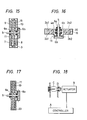
- a throttle valve control device for automobiles comprising a controller A, an actuator B for driving a throttle valve, and a throttle valve C, as shown in Fig.18.
- the present invention relates to a torque motor for use the actuator for the throttle valve C.
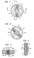
- Fig.l shows an inner structure view of a torque motor of one embodiment of the present invention which is omitted an upper part of a housing when viewed in the axial direction
- Fig.3 shows a sectional view taken along the line III-III in Fig.l
- Fig.4 shows a sectional view taken along the line IV-IV in Fig.l.
- a stationary core 1 made of magnetic permeable material having a doughnut-like disc form is rigidly supported by upper support 2al and 2a2 and by lower support 2bl and 2b2 made of plastic material respectively, each formed into a sector shape within a cylindrically formed housing 3, as shown in Fig.3.
- the same sectorally shaped upper support 2al and 2a2 is provided respectively within the housing 3 to opposite each other on the stationary core 1.
- the same sectorally shaped lower support 2bl and 2b2 is provided respectively within the housing 3 to opposite each other on the stationary core 1.
- both same sectorally shaped upper support 2al and lower support 2bl and the same sectorally shaped upper support 2a2 and lower support 2b2 are disposed respectively to overlap each other on the stationary core 1. And both the upper support 2al, 2a2 and the lower support 2bl, 2b2 rigidly support to sandwich the stationary core 1.
- a shaft 5 is provided through a pair of bearings 6a and 6b as shown Fig. 3 and Fig. 4.
- Two bands of belt-like coil assemblies 4a and 4b as shown in Fig.l are provided round the shaft 5 to surround the stationary core 1 without contacting the stationary core 1.
- the coils 4a and 4b are molded into position with a resin 11 as shown in Fig.3 and Fig.4.
- Two bands of coils 4a and 4b are provided to the outer surface of the stationary core 1, except for those portions including the upper support 2al, 2a2 and the lower support 2bl, 2b2 respectively.
- the two bands of coils 4a and 4b are provided to project from the outer surface of the stationary core 1 and to surround the stationary core 1.
- the coils 4a and 4b are turned within the stationary core 1, except for those portions including the upper support 2al, 2a2 and the lower support 2bl, 2b2 respectively as shown in Fig.2.
- the coils 4a and 4b are turned with the torque, it is capable of turning only within a finite range because of being stopped at the supports 2al, 2bl or the supports 2a2, 2b2 on the stationary core 1.
- such a finite turning range is set to be 85 0 .
- This value of the finit range is set to coincide with the degree of opening of the throttle valve C.
- the adjustable turning angle of the coils 4a and 4b can be increased or decreased by changing the size of the upper support 2al, 2a2 or the lower support 2bl, 2b2.
- magnets 7, 8 and 9, 10 are magnetized such that the inner side of the magnet 7 exhibits an N pole, the inner side of the magnet 8 exhibits an N pole, the inner side of the magnet 9 exhibits an S pole, and the inner side of the magnet 10 exhibits an S pole respectively.
- lead wires of the coils 4a and 4b are led out to the exterior of the housing 3 through the hollow inner portion of the shaft 5.
- magnetic flux emenates from the stationary core 1 to the magnet 10 with the side of the magnet 10 opposite to the stationary core 1 exhibiting an S pole. And current flows from lower to upper through the coils 4a and 4b crossing the magnetic flux thus produced, so that a force emenates from the front to the rear of the view shown in Fig.4.
- the output torque of the shaft 5 is determined from the forces produced on the coil 4a and 4b between the magnets 7, 8, 9 and 10 and the stationary core 1, as well as the as the distance between the coils 4a and 4b and the shaft center.
- the coils 4a and 4b are turned with the torque thus produced, it is capable of turning only within a finite range because of being stopped at the supports 2al, 2bl or at the supports 2a2, 2b2 on the stationary core 1.
- such a finite turning range is set to be 85°.
- This embodiment is a modified embodiment of the torque motor of Embodiment 1 shown from Fig.l to Fig.4.
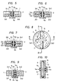
- Only the lower support 2bl and 2b2 for supporting the stationary core 1 is provided on one side of the housing 3 as shown in Fig.5.
- the stationary core 1 is fixed in a cantilevered manner by the lower support 2bl and 2b2. This reduces weight of the torque motor.
- This embodiment is a modified embodiment of the torque motor of Embodiment 1 shown from Fig.l to Fig.4.
- the stationary core comprises a two-stage core 12a and 12b using two doughnut-like disc plates placed one over the other as shown in Fig.6. And two separate stationary cores 12a and 12b are fixed without being in contact so as to produce a gap 12c therebetween.
- the upper stationary core 12a is fixed to the sector shaped supports 2al, 2bl and the lower stationary core 12b is fixed to the sectorally shaped supports 2a2, 2b2 respectively. This reduces weight of the torque motor.
- a still amother embodiment of the torque motor of the present invention will be described.
- This embodiment is a modified embodiment of the torque motor of Embodiment 3 shown in Fig.6.
- the gap 12c between the upper stationary core 12a and the lower stationary core 12B in Fig.6 is filled with a spacer 13 made of metal shown in Fig.7.
- This embodiment is a modified embodiment of the torque motor of Embodiment 1 shown from Fig.l to Fig.4.
- Fig.8 is an inner structure view of a torque motor, which is omitted an upper part of a housing, when viewed in the axial direction
- Fig.9 is a sectional view taken along the line IX-IX in Fig.8
- Fig.10 is a sectional view taken along the line X-X in Fig.8.
- the shaft is divided into two parts 14a and 14b to provide a structure such that one band of belt-like coil assembly 15 is interposed between the two separate shafts 14a and 14b thus divided.
- the coil 15 is molded with a resin 16 to surround the shafts 14a and 14b.
- the coil 15 is provided to the stationary core 1 therebetween, as shown in Fig.8, except for those portions including the sectorally shaped upper support 2al, 2a2 and the sectorally shaped lower support 2b, 2b2 respectively.
- the coil 15 is provided to project from the outer surface of the stationary core 1 and to surround the stationary core 1.
- This coil 15 turns the stationary core 1, except for those portions including the upper support 2al, 2a2 and the lower support 2bl, 2b2 respectively.
- This embodiment is a modified embodiment of the torque motor of Embodiment 5 shown from Fig.8 to Fig.10.
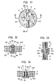
- Fig.ll is an inner structure view of a torque motor, which is omitted an upper part of a housing, when viewed in the axial direction
- Fig.12 is a sectional view taken along the line XII-XII in Fig.ll
- Fig.13 is a sectional view taken along the line XIII-XIII in Fig.ll.
- a complete disc plate 17 is employed as the stationary core, as shown from Fig.ll to Fig.13, in place of the doughnut-like disc core as illustrated in the embodiment of Fig.9.
- the coil 15 is molded with a resin 18.
- This embodiment is a modified embodiment of the torque motor of Embodiment 1 shown from Fig.l to fig.4.
- a magnet 19 shown Fig.14 and Fig.15, in place of the stationary core. More specifically, the magnets 7, 8, 9 and 10 are arranged and magnetized similarly to those explained in connection with Fig.l to Fig.4. Whereas the magnet 19 is magnetized to exhibit an S pole on the lower side of Fig.15 and an N pole on the upper side thereof. The strength of magnetic flux between each of the magnets 7, 8, 9 and 10 and the magnet 19 can be increased.
- This embodiment is a modified the torque motor of Embodiment 7 shown in Fig.14 and Fig.15.
- a housing 20 is arranged to approach the coils 4a and 4b, magnetic flux emenates from the magnet 19 to the housing 20 to form a magnetic circuit, thereby producing forces on the coils 4a and 4b.
Landscapes
- Engineering & Computer Science (AREA)
- Power Engineering (AREA)
- Chemical & Material Sciences (AREA)
- Combustion & Propulsion (AREA)
- Mechanical Engineering (AREA)
- General Engineering & Computer Science (AREA)
- Reciprocating, Oscillating Or Vibrating Motors (AREA)
- Control Of Throttle Valves Provided In The Intake System Or In The Exhaust System (AREA)
- Connection Of Motors, Electrical Generators, Mechanical Devices, And The Like (AREA)
- Permanent Magnet Type Synchronous Machine (AREA)
Applications Claiming Priority (2)
| Application Number | Priority Date | Filing Date | Title |
|---|---|---|---|
| JP59158258A JPH0624417B2 (ja) | 1984-07-27 | 1984-07-27 | トルクモータ |
| JP158258/84 | 1984-07-27 |
Publications (3)
| Publication Number | Publication Date |
|---|---|
| EP0169578A2 true EP0169578A2 (fr) | 1986-01-29 |
| EP0169578A3 EP0169578A3 (en) | 1987-05-27 |
| EP0169578B1 EP0169578B1 (fr) | 1989-11-15 |
Family
ID=15667687
Family Applications (1)
| Application Number | Title | Priority Date | Filing Date |
|---|---|---|---|
| EP85109418A Expired EP0169578B1 (fr) | 1984-07-27 | 1985-07-26 | Moteur couple |
Country Status (6)
| Country | Link |
|---|---|
| US (1) | US4639624A (fr) |
| EP (1) | EP0169578B1 (fr) |
| JP (1) | JPH0624417B2 (fr) |
| KR (1) | KR900003989B1 (fr) |
| CA (1) | CA1234407A (fr) |
| DE (1) | DE3574315D1 (fr) |
Families Citing this family (20)
| Publication number | Priority date | Publication date | Assignee | Title |
|---|---|---|---|---|
| GB8912537D0 (en) * | 1989-06-01 | 1989-07-19 | Lucas Ind Plc | Throttle actuator and control system |
| DE4019823C2 (de) * | 1989-06-21 | 1996-11-14 | Hitachi Metals Ltd | Schwenk-Betätigungseinrichtung |
| US5148071A (en) * | 1990-03-22 | 1992-09-15 | Hitachi Metals, Ltd. | Swing-type actuator with thin reinforced movable coil |
| US5165090A (en) * | 1990-05-24 | 1992-11-17 | Hitachi Metals, Ltd. | Swing-type actuator |
| US5168184A (en) * | 1990-10-04 | 1992-12-01 | Hitachi Metals, Ltd. | Swing-type actuator |
| US5168185A (en) * | 1990-10-09 | 1992-12-01 | Hitachi Metals, Ltd. | Swing-type actuator |
| US5576583A (en) * | 1992-04-30 | 1996-11-19 | Hitachi Metals, Ltd. | Swing-type actuator |
| DE4314167C2 (de) * | 1992-04-30 | 1995-04-13 | Hitachi Metals Ltd | Magnetanordnung für einen Pendel-Stellantrieb |
| US5581422A (en) * | 1993-02-09 | 1996-12-03 | Hitachi Metals, Ltd. | Actuator with moveable coil and recording apparatus |
| US5382851A (en) * | 1994-05-04 | 1995-01-17 | Xolox Corporation | Swing-type actuator |
| EP0984549A1 (fr) * | 1997-10-28 | 2000-03-08 | Caspar Hohoff | Moteur-couple pour un entraínement pour un actionneur avec une course de reglage de 0 à 90 degrés pour le positionnement de vannes papillon ou de vannes rotatives pour des moteurs de véhicules |
| US6106682A (en) * | 1998-05-22 | 2000-08-22 | Cvc Products, Inc. | Thin-film processing electromagnet for low-skew magnetic orientation |
| DE19852650A1 (de) * | 1998-11-16 | 2000-05-25 | Joerg Bobzin | Elektrische Maschine |
| JP3790214B2 (ja) * | 2002-12-17 | 2006-06-28 | 株式会社 アサバ | コアレスモータ |
| FR2910739B1 (fr) * | 2006-12-21 | 2009-03-06 | Teleflex Automotive France Sas | Actionneur electrique, en particulier pour l'entrainement d'un arbre de selection d'une boite de vitesses. |
| RU2337458C1 (ru) * | 2007-07-18 | 2008-10-27 | Андрей Борисович Захаренко | Торцевая магнитоэлектрическая машина (варианты) |
| RU2339147C1 (ru) * | 2007-11-13 | 2008-11-20 | Андрей Борисович Захаренко | Электрическая машина |
| US9739218B2 (en) * | 2015-10-06 | 2017-08-22 | Kohler Co. | Throttle drive actuator for an engine |
| US10815908B2 (en) | 2015-10-06 | 2020-10-27 | Kohler Co. | Throttle drive actuator for an engine |
| WO2024054587A1 (fr) * | 2022-09-08 | 2024-03-14 | Woodward, Inc. | Limiteur de deplacement d'induit |
Family Cites Families (12)
| Publication number | Priority date | Publication date | Assignee | Title |
|---|---|---|---|---|
| FR1341582A (fr) * | 1962-09-11 | 1963-11-02 | Electronique & Automatisme Sa | Perfectionnements aux machines électriques tournantes |
| US3530380A (en) * | 1966-05-05 | 1970-09-22 | Weston Instruments Inc | Moving coil instrument having a magnetic detent mechanism |
| FR2049558A5 (fr) * | 1969-06-13 | 1971-03-26 | Compteurs Comp D | |
| GB1352127A (en) * | 1970-08-11 | 1974-05-08 | Lucas Industries Ltd | Electromagnetic torque motor |
| JPS537610U (fr) * | 1976-07-06 | 1978-01-23 | ||
| JPS5310807A (en) * | 1976-07-17 | 1978-01-31 | Osamu Taniguchi | Movable coil torque actuator |
| DE3001473A1 (de) * | 1980-01-17 | 1981-07-23 | Robert Bosch Gmbh, 7000 Stuttgart | Stelleinrichtung zur drehwinkeleinstellung |
| IT1142978B (it) * | 1980-10-29 | 1986-10-15 | Pierburg Gmbh & Co Kg | Regolatore rotativo in particolare per carburatori di motori a combustione interna |
| JPS57180487A (en) * | 1981-04-30 | 1982-11-06 | Matsushita Electric Works Ltd | Purification tank |
| US4443724A (en) * | 1982-02-19 | 1984-04-17 | The United States Of America As Represented By The Administrator Of The National Aeronautics And Space Administration | Shaft transducer having DC output proportional to angular velocity |
| US4558937A (en) * | 1984-02-06 | 1985-12-17 | Polaroid Corporation | Electromagnetic blade mechanism |
| US4553058A (en) * | 1984-03-30 | 1985-11-12 | Aisin Seiki Kabushiki Kaisha | Low profile direct current motor |
-
1984
- 1984-07-27 JP JP59158258A patent/JPH0624417B2/ja not_active Expired - Lifetime
-
1985
- 1985-07-15 KR KR1019850005033A patent/KR900003989B1/ko not_active Expired
- 1985-07-24 CA CA000487395A patent/CA1234407A/fr not_active Expired
- 1985-07-26 EP EP85109418A patent/EP0169578B1/fr not_active Expired
- 1985-07-26 DE DE8585109418T patent/DE3574315D1/de not_active Expired
- 1985-07-29 US US06/759,964 patent/US4639624A/en not_active Expired - Fee Related
Also Published As
| Publication number | Publication date |
|---|---|
| US4639624A (en) | 1987-01-27 |
| KR900003989B1 (ko) | 1990-06-07 |
| KR860001286A (ko) | 1986-02-24 |
| EP0169578A3 (en) | 1987-05-27 |
| EP0169578B1 (fr) | 1989-11-15 |
| JPH0624417B2 (ja) | 1994-03-30 |
| CA1234407A (fr) | 1988-03-22 |
| JPS6139839A (ja) | 1986-02-26 |
| DE3574315D1 (en) | 1989-12-21 |
Similar Documents
| Publication | Publication Date | Title |
|---|---|---|
| EP0169578A2 (fr) | Moteur couple | |
| JP2000253635A (ja) | アキシャルギャップモータ | |
| JP2000069734A (ja) | 直流トルクモ―タ及びその製造方法 | |
| JPH0340869U (fr) | ||
| US4839552A (en) | Brushless DC motor | |
| JP2000078783A (ja) | 電気モータ | |
| GB2288488A (en) | Limited angular deflection type rotary electromagnetic actuator | |
| JPH0135583Y2 (fr) | ||
| JP2003314550A (ja) | 磁気軸受装置 | |
| JPS6070958A (ja) | アウタロ−タステップモ−タ構造 | |
| JPS5930619Y2 (ja) | 可動コイル形円弧モ−タ− | |
| JPH056594Y2 (fr) | ||
| JPS6216056A (ja) | ステツピングモ−タ | |
| JPS6421215A (en) | Triaxial control magnetic bearing apparatus | |
| JPH0223103Y2 (fr) | ||
| JP2543533Y2 (ja) | 電磁式有限回転型電動機の回転子原点復帰機構 | |
| JPS6334463Y2 (fr) | ||
| JPS5930620Y2 (ja) | 可動コイル型円弧モ−タ− | |
| JPS62199717U (fr) | ||
| JPH01157575U (fr) | ||
| JPS59113762A (ja) | 円弧モ−タ | |
| JPS62233054A (ja) | モ−タ | |
| JPS62110464A (ja) | モ−タ用ロ−タ磁石 | |
| JPH0289653U (fr) | ||
| JPS62110465A (ja) | モ−タ用ロ−タ磁石 |
Legal Events
| Date | Code | Title | Description |
|---|---|---|---|
| PUAI | Public reference made under article 153(3) epc to a published international application that has entered the european phase |
Free format text: ORIGINAL CODE: 0009012 |
|
| AK | Designated contracting states |
Designated state(s): CH DE FR GB IT LI NL SE |
|
| PUAL | Search report despatched |
Free format text: ORIGINAL CODE: 0009013 |
|
| AK | Designated contracting states |
Kind code of ref document: A3 Designated state(s): CH DE FR GB IT LI NL SE |
|
| 17P | Request for examination filed |
Effective date: 19870529 |
|
| 17Q | First examination report despatched |
Effective date: 19890301 |
|
| RBV | Designated contracting states (corrected) |
Designated state(s): DE GB |
|
| GRAA | (expected) grant |
Free format text: ORIGINAL CODE: 0009210 |
|
| AK | Designated contracting states |
Kind code of ref document: B1 Designated state(s): DE GB |
|
| REF | Corresponds to: |
Ref document number: 3574315 Country of ref document: DE Date of ref document: 19891221 |
|
| PLBE | No opposition filed within time limit |
Free format text: ORIGINAL CODE: 0009261 |
|
| STAA | Information on the status of an ep patent application or granted ep patent |
Free format text: STATUS: NO OPPOSITION FILED WITHIN TIME LIMIT |
|
| 26N | No opposition filed | ||
| PGFP | Annual fee paid to national office [announced via postgrant information from national office to epo] |
Ref country code: GB Payment date: 19930716 Year of fee payment: 9 |
|
| PG25 | Lapsed in a contracting state [announced via postgrant information from national office to epo] |
Ref country code: GB Effective date: 19940726 |
|
| GBPC | Gb: european patent ceased through non-payment of renewal fee |
Effective date: 19940726 |
|
| PGFP | Annual fee paid to national office [announced via postgrant information from national office to epo] |
Ref country code: DE Payment date: 19970930 Year of fee payment: 13 |
|
| PG25 | Lapsed in a contracting state [announced via postgrant information from national office to epo] |
Ref country code: DE Free format text: LAPSE BECAUSE OF NON-PAYMENT OF DUE FEES Effective date: 19990501 |