EP0168945B1 - Gripper for a programmable manipulator - Google Patents
Gripper for a programmable manipulator Download PDFInfo
- Publication number
- EP0168945B1 EP0168945B1 EP85304075A EP85304075A EP0168945B1 EP 0168945 B1 EP0168945 B1 EP 0168945B1 EP 85304075 A EP85304075 A EP 85304075A EP 85304075 A EP85304075 A EP 85304075A EP 0168945 B1 EP0168945 B1 EP 0168945B1
- Authority
- EP
- European Patent Office
- Prior art keywords
- gripper
- arm
- finger element
- frame member
- finger
- Prior art date
- Legal status (The legal status is an assumption and is not a legal conclusion. Google has not performed a legal analysis and makes no representation as to the accuracy of the status listed.)
- Expired
Links
- 230000015572 biosynthetic process Effects 0.000 claims description 7
- 238000005755 formation reaction Methods 0.000 claims description 7
- 238000006073 displacement reaction Methods 0.000 claims description 5
- 230000000694 effects Effects 0.000 claims description 3
- 238000013459 approach Methods 0.000 description 2
- 238000003780 insertion Methods 0.000 description 2
- 230000037431 insertion Effects 0.000 description 2
- 238000003801 milling Methods 0.000 description 2
- 238000007493 shaping process Methods 0.000 description 2
- 230000003247 decreasing effect Effects 0.000 description 1
- 238000000034 method Methods 0.000 description 1
- 239000000523 sample Substances 0.000 description 1
- 238000000926 separation method Methods 0.000 description 1
- 230000035939 shock Effects 0.000 description 1
Images

Classifications
-
- B—PERFORMING OPERATIONS; TRANSPORTING
- B25—HAND TOOLS; PORTABLE POWER-DRIVEN TOOLS; MANIPULATORS
- B25J—MANIPULATORS; CHAMBERS PROVIDED WITH MANIPULATION DEVICES
- B25J15/00—Gripping heads and other end effectors
- B25J15/04—Gripping heads and other end effectors with provision for the remote detachment or exchange of the head or parts thereof
- B25J15/0475—Exchangeable fingers
Definitions
- the present invention relates to a gripper apparatus for a programmable manipulator, and more particularly to such a gripper apparatus which enables the handling of a wide variety of differently shaped articles.
- programmable manipulators are to be used for assembly as part of a flexible work station capable of the assembly of a variety of different products, the gripper of the manipulator must be capable of picking up a wide variety of different components. Attempts have been made to construct a "universal" gripper, often based upon the human hand, but they tend to be expensive and often not able to perform handling operations satisfactorily.
- US-4 372 728 describes a tool transfer arm assembly for an automatic milling machine.
- the assembly includes a magazine storing a number of different tools for use with the milling machine, and a transfer arm arranged to remove a selected tool from the magazine, and to return it to the magazine after use.
- the transfer arm has a pair of cooperable jaws arranged to grip a selected tool, and the arm is manoevred into the correct position by a succession of linear and rotational movements.
- a transfer mechanism of this kind is unsuitable for use in some automated arrangements which require a more rapid transfer capability.
- the present invention provides a gripper apparatus for a programmable manipulator, the apparatus comprising a gripper arm; at least one article-handling finger element, the arm and the finger element having co-operable, inter- engageable formations whereby the finger element may be mounted detachably on the arms and an assembly station arranged to hold the finger element releasably and including a body member, characterised in that the assembly station further includes a frame member displaceable with respect to the body member and latching means for holding the finger element releasably against the frame member;
- the finger elements used in the gripping apparatus can be low cost items because they can consist essentially only of a section to effect connection with the gripper mount and a section shaped for the handling operation. Also they can be tailored to suit the precise requirements of the component for handling, thereby ensuring improved handling performance and adequate control during the assembly process.
- the co-operating parts on the gripper mount and on the finger elements are of conical form; also preferably the gripper mount or the finger elements have releasable means to effect locking of the two parts and/or means to prevent relative rotation of the two parts.
- the Figures illustrate a manipulator gripper attachment system which has a gripper being capable of holding any one of a number of readily-detachably fingers, each designed for a specific handling operation; the system also incorporates an assembly rack for holding the fingers when not in use and for providing quick and easy assembly and detachment of the gripper and finger.
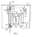
- the assembly rack consists of an elongate horizontal plate 1 having a number of locations (only one being illustrated) at which a finger 2 can be held.
- Each finger has a conical section 3 for engagement with a co-operating recess on the gripper, a web 4 extending between the conical section 3 and a flat shield 5, from which there projects a finger element 6 with an end surface 7 whose profile is designed specifically for a particular handling operation.
- the profiled end surface is in the form of an elongate, straight-sided groove; such a finger may be used (together with another gripper and finger of similar, or flat, profile) for holding a length of rod.
- profiled end surface is in the form of an elongate, straight-sided groove; such a finger may be used (together with another gripper and finger of similar, or flat, profile) for holding a length of rod.
- Profiled ends for other applications may have any of the following shapes: elongate grooves of different dimensions and/or with arcuate sides; recesses of various cross-sections whether straight-sided (e.g. triangular), arcuate (e.g. circular) or a combination, the recesses being of various depths and having various contours of base surfaces; projections of various shapes and dimensions forming e.g. a probe or a screwdriver head (of standard or Philips (Registered Trade Mark) format).
- Figure 2 shows the form of engagement in the assembled gripper between finger 2 and a gripper mount 10 which is located on the end of the manipulator arm.
- a conical recess 11 in gripper mount and of appropriate dimensions receives the conical section 3, which is restrained from rotation therein by lug 12 projecting from gripper mount 10 into part of a recess 8 (see Figure 3).
- the recess 8 has a length substantially greater than necessary to accommodate the lug 12, its depth decreasing towards the narrow end of conical section 3.
- a pin 13 having spring-loading 14 engages with a recess 18 of comparable dimensions in section 3.
- the pin 13 has a roller 16 located on an extension 17 such that, when roller 16 is urged away from mount 10, latch pin 13 is moved out of engagement with recess 15 against the action of spring-loading 14, thereby permitting finger section 3 to be withdrawn from recess 11.
- a finger 2 is held in a slot 19 within a tray 20 by means of two latches 21 and 22 each of which is pivotally mounted on tray 20 at hinge-pins 23, 24.
- the tray 20 is held within a slot 25 of rack plate 1 by means of one of lateral edge of the tray slideably engaging in grooved edge 26 of slot 25, while the opposite edge of the tray is attached to a rod 27 which is mounted against plate 1 via loops 28 in order to be able to move vertically while restrained horizontally.
- Two sets of springs 29 and 30, located around rod 27, return tray 20 to a predetermined position in slot 25 when external forces are removed.
- Latches 21 and 22 have a generally L-shape, each with a roller 31, 32 at the free end of the shorter section; each roller is postioned to contact with a cam surface 33, 34.
- the finger 2 Prior to the operation of assembling the finger 2 onto the gripper mount 10, the finger 2 is held in the rack in the position shown in Figure 1.
- the gripper mount 10 approaches, from above and on the side of the rack opposite to that shown in Figure 7, moving in a downward direction.
- the programmable manipulator control system can guide the gripper mount 10 such as to ensure that the recess 11 passes over and around the conical section 3 to enable engagement and then locking of these two parts by means of pin 13.
- the conical shaping of these two cooperating parts guides them together and encourages their correct alignment, thereby compensating for the minor inaccuracies that might occur in the path taken by the mount 10.
- the included angle of the conical shaping used for these parts is greater than is necessary for overcoming this misalignment problem in order to effectively eliminate jamming of the parts during their engagement.
- a tolerance on path position of ⁇ 2 mm can readily be achieved, this being quite adequate even for existing standard programmable manipulators.
- section 3 is movable laterally relative to the direction of motion of mount 10.
- finger 2 is jiggled laterally until correct alignment and engagement is achieved. Forward motion of finger 2 is prevented at this stage by the notches 35, 36 on latches 21, 22.
- the put-down operation for returning the finger 2 to the tray 20 is essentially the reverse of the pick-up operation.
- roller 16 engages with another cam surface 37 on rack plate 1 which withdraws pin 13 from recess 15.
- latches 21 and 22 As the upwardly moving top edge of the finger's shield 5 contacts the inclined ends of latches 21 and 22, the latter are urged laterally apart to allow the finger 2 to pass through, whereupon the latches snap-to behind.
- the final separation of the finger 2 and gripper mount 10 is caused when the finger 2 hits the top edge of the slot of tray 20. Any shock loading incurred by this is absorbed by the springs 29, 30.
Landscapes
- Engineering & Computer Science (AREA)
- Robotics (AREA)
- Mechanical Engineering (AREA)
- Manipulator (AREA)
Applications Claiming Priority (2)
| Application Number | Priority Date | Filing Date | Title |
|---|---|---|---|
| GB8415498 | 1984-06-18 | ||
| GB848415498A GB8415498D0 (en) | 1984-06-18 | 1984-06-18 | Gripper |
Publications (2)
| Publication Number | Publication Date |
|---|---|
| EP0168945A1 EP0168945A1 (en) | 1986-01-22 |
| EP0168945B1 true EP0168945B1 (en) | 1988-06-29 |
Family
ID=10562601
Family Applications (1)
| Application Number | Title | Priority Date | Filing Date |
|---|---|---|---|
| EP85304075A Expired EP0168945B1 (en) | 1984-06-18 | 1985-06-10 | Gripper for a programmable manipulator |
Country Status (5)
| Country | Link |
|---|---|
| US (1) | US4645407A (enExample) |
| EP (1) | EP0168945B1 (enExample) |
| JP (1) | JPS6114885A (enExample) |
| DE (1) | DE3563518D1 (enExample) |
| GB (1) | GB8415498D0 (enExample) |
Cited By (1)
| Publication number | Priority date | Publication date | Assignee | Title |
|---|---|---|---|---|
| DE3901655A1 (de) * | 1988-01-20 | 1989-08-03 | Fraunhofer Ges Forschung | Werkzeugsystem mit wechselbaren werkzeug-elementen |
Families Citing this family (6)
| Publication number | Priority date | Publication date | Assignee | Title |
|---|---|---|---|---|
| JPH0453914Y2 (enExample) * | 1986-09-16 | 1992-12-17 | ||
| US4852242A (en) * | 1988-03-24 | 1989-08-01 | Hewlett-Packard Company | Tool coupling apparatus and method |
| US5056844A (en) * | 1990-03-06 | 1991-10-15 | Amistar Corporation | Multiple jaw centering head structure for surface mounted component placement machines |
| US5486030A (en) * | 1994-05-04 | 1996-01-23 | Abc Packaging Machine Corporation | Apparatus and method for lifting and depositing bottles having handles |
| US8967691B2 (en) | 2012-10-16 | 2015-03-03 | Beckman Coulter, Inc. | Chute arrangement with strip-off feature |
| CN113211482B (zh) * | 2021-04-29 | 2022-09-23 | 南京埃斯顿智能系统工程有限公司 | 自动快速交换的翼型轴承座专用夹具 |
Family Cites Families (13)
| Publication number | Priority date | Publication date | Assignee | Title |
|---|---|---|---|---|
| JPS5124789Y2 (enExample) * | 1971-08-14 | 1976-06-24 | ||
| US3848753A (en) * | 1972-04-14 | 1974-11-19 | Electrolux Ab | Turning movement device for material handling apparatus |
| US4046263A (en) * | 1976-07-29 | 1977-09-06 | General Motors Corporation | Tool changing apparatus for a multi-axis manipulator |
| DE2819622A1 (de) * | 1978-05-05 | 1979-11-08 | Festo Maschf Stoll G | Greifzange fuer manipulatoren, roboter o.dgl. |
| US4227853A (en) * | 1979-02-06 | 1980-10-14 | Spar Aerospace Limited | Manipulator wrist tool interface |
| US4281447A (en) * | 1979-03-01 | 1981-08-04 | Mcdonnell Douglas Corporation | Detachable tool interface system for a robot |
| US4372728A (en) * | 1981-01-02 | 1983-02-08 | Enshu Limited | Tool transfer arm assembly for automatic milling machines |
| US4488241A (en) * | 1981-12-08 | 1984-12-11 | Zymark Corporation | Robot system with interchangeable hands |
| JPS58137593A (ja) * | 1982-02-10 | 1983-08-16 | ぺんてる株式会社 | ロボツトのフインガ−自動交換装置 |
| JPS58121691U (ja) * | 1982-02-15 | 1983-08-18 | 三菱電機株式会社 | つかみ装置の把持爪取付機構 |
| DE3214025A1 (de) * | 1982-04-16 | 1983-10-20 | Messerschmitt-Bölkow-Blohm GmbH, 8000 München | Zweiteilige einrichtung mit kegelhuelse und kegelschaft |
| JPS59148290U (ja) * | 1983-03-23 | 1984-10-03 | 日立精機株式会社 | ロボツトハンドの爪交換装置 |
| US4512709A (en) * | 1983-07-25 | 1985-04-23 | Cincinnati Milacron Inc. | Robot toolchanger system |
-
1984
- 1984-06-18 GB GB848415498A patent/GB8415498D0/en active Pending
-
1985
- 1985-06-10 EP EP85304075A patent/EP0168945B1/en not_active Expired
- 1985-06-10 DE DE8585304075T patent/DE3563518D1/de not_active Expired
- 1985-06-17 US US06/744,947 patent/US4645407A/en not_active Expired - Lifetime
- 1985-06-17 JP JP60130095A patent/JPS6114885A/ja active Granted
Cited By (1)
| Publication number | Priority date | Publication date | Assignee | Title |
|---|---|---|---|---|
| DE3901655A1 (de) * | 1988-01-20 | 1989-08-03 | Fraunhofer Ges Forschung | Werkzeugsystem mit wechselbaren werkzeug-elementen |
Also Published As
| Publication number | Publication date |
|---|---|
| JPS6114885A (ja) | 1986-01-23 |
| EP0168945A1 (en) | 1986-01-22 |
| JPH0585314B2 (enExample) | 1993-12-07 |
| GB8415498D0 (en) | 1984-07-25 |
| US4645407A (en) | 1987-02-24 |
| DE3563518D1 (en) | 1988-08-04 |
Similar Documents
| Publication | Publication Date | Title |
|---|---|---|
| USRE40578E1 (en) | Apparatus for changing operating modules on a coordinate positioning machine | |
| EP0155362B1 (en) | Manipulator gripper tool changing apparatus | |
| US4658494A (en) | Apparatus for drilling printed circuit boards | |
| US4852242A (en) | Tool coupling apparatus and method | |
| EP0344954A1 (en) | Gripper head | |
| EP0118052A1 (en) | Robot object manipulator with changeable finger tools | |
| EP0168945B1 (en) | Gripper for a programmable manipulator | |
| JPH01289634A (ja) | 工作機械の工具交換装置 | |
| US5481794A (en) | Device for handling objects and method of using same | |
| EP0171715B1 (en) | Method of cutting slide fastener chain | |
| US4583288A (en) | Apparatus for the acquistion and insertion of dual in-line package components | |
| EP0007183B1 (en) | An electrical connector assembly and apparatus for, and a method of, manufacturing the assembly | |
| EP0716484A2 (en) | Terminal inserting apparatus | |
| US4455044A (en) | Tool for picking up and inserting different length bolts | |
| EP0204451B1 (en) | Circuit assembly system | |
| CA1322841C (en) | Electronic component insertion machine | |
| EP0340921B1 (en) | Electronic component insertion machine | |
| SU1468746A1 (ru) | Устройство дл автоматической смены захватов | |
| JPS61180618A (ja) | 折曲げ加工製品の製造方法および装置 | |
| CN120422310A (zh) | 换刀系统、电路板加工系统及换刀方法 | |
| CN120962694A (zh) | 一种料盘夹取爪手 | |
| SU1466018A1 (ru) | Ручка-съемник | |
| EP0318068A1 (en) | A component lead straightening apparatus | |
| JPS60248000A (ja) | 插入ハンドへの電子部品装着装置 | |
| JPH0751961A (ja) | 治具プレート着脱装置 |
Legal Events
| Date | Code | Title | Description |
|---|---|---|---|
| PUAI | Public reference made under article 153(3) epc to a published international application that has entered the european phase |
Free format text: ORIGINAL CODE: 0009012 |
|
| AK | Designated contracting states |
Designated state(s): DE GB SE |
|
| 17P | Request for examination filed |
Effective date: 19860521 |
|
| 17Q | First examination report despatched |
Effective date: 19870911 |
|
| GRAA | (expected) grant |
Free format text: ORIGINAL CODE: 0009210 |
|
| AK | Designated contracting states |
Kind code of ref document: B1 Designated state(s): DE GB SE |
|
| REF | Corresponds to: |
Ref document number: 3563518 Country of ref document: DE Date of ref document: 19880804 |
|
| PLBE | No opposition filed within time limit |
Free format text: ORIGINAL CODE: 0009261 |
|
| STAA | Information on the status of an ep patent application or granted ep patent |
Free format text: STATUS: NO OPPOSITION FILED WITHIN TIME LIMIT |
|
| 26N | No opposition filed | ||
| REG | Reference to a national code |
Ref country code: GB Ref legal event code: 732 |
|
| EAL | Se: european patent in force in sweden |
Ref document number: 85304075.6 |
|
| PGFP | Annual fee paid to national office [announced via postgrant information from national office to epo] |
Ref country code: SE Payment date: 19980616 Year of fee payment: 14 Ref country code: GB Payment date: 19980616 Year of fee payment: 14 |
|
| PGFP | Annual fee paid to national office [announced via postgrant information from national office to epo] |
Ref country code: DE Payment date: 19980626 Year of fee payment: 14 |
|
| PG25 | Lapsed in a contracting state [announced via postgrant information from national office to epo] |
Ref country code: GB Free format text: LAPSE BECAUSE OF NON-PAYMENT OF DUE FEES Effective date: 19990610 |
|
| PG25 | Lapsed in a contracting state [announced via postgrant information from national office to epo] |
Ref country code: SE Free format text: THE PATENT HAS BEEN ANNULLED BY A DECISION OF A NATIONAL AUTHORITY Effective date: 19990629 |
|
| GBPC | Gb: european patent ceased through non-payment of renewal fee |
Effective date: 19990610 |
|
| EUG | Se: european patent has lapsed |
Ref document number: 85304075.6 |
|
| PG25 | Lapsed in a contracting state [announced via postgrant information from national office to epo] |
Ref country code: DE Free format text: LAPSE BECAUSE OF NON-PAYMENT OF DUE FEES Effective date: 20000503 |