EP0168942B1 - Lead screw and nut assembly - Google Patents
Lead screw and nut assembly Download PDFInfo
- Publication number
- EP0168942B1 EP0168942B1 EP85304018A EP85304018A EP0168942B1 EP 0168942 B1 EP0168942 B1 EP 0168942B1 EP 85304018 A EP85304018 A EP 85304018A EP 85304018 A EP85304018 A EP 85304018A EP 0168942 B1 EP0168942 B1 EP 0168942B1
- Authority
- EP
- European Patent Office
- Prior art keywords
- lead screw
- roller means
- ring
- rollers
- screw
- Prior art date
- Legal status (The legal status is an assumption and is not a legal conclusion. Google has not performed a legal analysis and makes no representation as to the accuracy of the status listed.)
- Expired
Links
- 230000005540 biological transmission Effects 0.000 claims abstract description 10
- 230000033001 locomotion Effects 0.000 claims description 10
- 230000014759 maintenance of location Effects 0.000 claims description 5
- 230000036316 preload Effects 0.000 claims description 3
- 230000000717 retained effect Effects 0.000 claims description 2
- 230000004323 axial length Effects 0.000 claims 1
- 238000005096 rolling process Methods 0.000 abstract description 4
- 238000000227 grinding Methods 0.000 description 3
- 238000006073 displacement reaction Methods 0.000 description 2
- 238000009826 distribution Methods 0.000 description 2
- 230000000712 assembly Effects 0.000 description 1
- 238000000429 assembly Methods 0.000 description 1
- 230000000694 effects Effects 0.000 description 1
- 238000009434 installation Methods 0.000 description 1
- 238000003754 machining Methods 0.000 description 1
- 238000000034 method Methods 0.000 description 1
- 238000003801 milling Methods 0.000 description 1
- 238000012986 modification Methods 0.000 description 1
- 230000004048 modification Effects 0.000 description 1
- 230000002441 reversible effect Effects 0.000 description 1
Images


Classifications
-
- F—MECHANICAL ENGINEERING; LIGHTING; HEATING; WEAPONS; BLASTING
- F16—ENGINEERING ELEMENTS AND UNITS; GENERAL MEASURES FOR PRODUCING AND MAINTAINING EFFECTIVE FUNCTIONING OF MACHINES OR INSTALLATIONS; THERMAL INSULATION IN GENERAL
- F16H—GEARING
- F16H25/00—Gearings comprising primarily only cams, cam-followers and screw-and-nut mechanisms
- F16H25/18—Gearings comprising primarily only cams, cam-followers and screw-and-nut mechanisms for conveying or interconverting oscillating or reciprocating motions
- F16H25/20—Screw mechanisms
- F16H25/22—Screw mechanisms with balls, rollers, or similar members between the co-operating parts; Elements essential to the use of such members
- F16H25/2247—Screw mechanisms with balls, rollers, or similar members between the co-operating parts; Elements essential to the use of such members with rollers
- F16H25/2266—Screw mechanisms with balls, rollers, or similar members between the co-operating parts; Elements essential to the use of such members with rollers arranged substantially in parallel to the screw shaft axis
-
- F—MECHANICAL ENGINEERING; LIGHTING; HEATING; WEAPONS; BLASTING
- F16—ENGINEERING ELEMENTS AND UNITS; GENERAL MEASURES FOR PRODUCING AND MAINTAINING EFFECTIVE FUNCTIONING OF MACHINES OR INSTALLATIONS; THERMAL INSULATION IN GENERAL
- F16H—GEARING
- F16H25/00—Gearings comprising primarily only cams, cam-followers and screw-and-nut mechanisms
- F16H25/18—Gearings comprising primarily only cams, cam-followers and screw-and-nut mechanisms for conveying or interconverting oscillating or reciprocating motions
- F16H25/20—Screw mechanisms
- F16H25/22—Screw mechanisms with balls, rollers, or similar members between the co-operating parts; Elements essential to the use of such members
- F16H25/2247—Screw mechanisms with balls, rollers, or similar members between the co-operating parts; Elements essential to the use of such members with rollers
- F16H25/2252—Planetary rollers between nut and screw
-
- Y—GENERAL TAGGING OF NEW TECHNOLOGICAL DEVELOPMENTS; GENERAL TAGGING OF CROSS-SECTIONAL TECHNOLOGIES SPANNING OVER SEVERAL SECTIONS OF THE IPC; TECHNICAL SUBJECTS COVERED BY FORMER USPC CROSS-REFERENCE ART COLLECTIONS [XRACs] AND DIGESTS
- Y10—TECHNICAL SUBJECTS COVERED BY FORMER USPC
- Y10T—TECHNICAL SUBJECTS COVERED BY FORMER US CLASSIFICATION
- Y10T74/00—Machine element or mechanism
- Y10T74/19—Gearing
- Y10T74/19642—Directly cooperating gears
- Y10T74/19698—Spiral
- Y10T74/19702—Screw and nut
- Y10T74/19744—Rolling element engaging thread
- Y10T74/19781—Non-recirculating rolling elements
- Y10T74/19791—Cylindrical or quasi-cylindrical roller element [e.g., inclined roller, etc.]
- Y10T74/19795—Parallel to shaft
-
- Y—GENERAL TAGGING OF NEW TECHNOLOGICAL DEVELOPMENTS; GENERAL TAGGING OF CROSS-SECTIONAL TECHNOLOGIES SPANNING OVER SEVERAL SECTIONS OF THE IPC; TECHNICAL SUBJECTS COVERED BY FORMER USPC CROSS-REFERENCE ART COLLECTIONS [XRACs] AND DIGESTS
- Y10—TECHNICAL SUBJECTS COVERED BY FORMER USPC
- Y10T—TECHNICAL SUBJECTS COVERED BY FORMER US CLASSIFICATION
- Y10T74/00—Machine element or mechanism
- Y10T74/19—Gearing
- Y10T74/1987—Rotary bodies
- Y10T74/19893—Sectional
- Y10T74/19898—Backlash take-up
- Y10T74/19902—Screw and nut
Definitions
- This invention relates to an improved mechanical device for converting a rotary input to a linear output, and more particularly to an improved lead screw and nut assembly.
- the ordinary lead screw-nut combination is very inefficient due to the fact that the sliding screw thread surfaces are subject to output loads which result in large friction losses.
- Various devices have been used to reduce the friction such as a ball-nut, and a roller-nut.
- the present invention is related to a device that is intended to perform the same function but more simply, more efficiently, and at lower cost.
- conventional devices include a threaded lead screw and a nut unit.
- the nut unit commonly comprises an assembly having an outer case that houses anti-friction elements engaging the threaded lead screw and normally surround it for load distribution purposes.
- As an . example, of this US-A-3 003 362 uses a toroidal shaped bearing element in engagement with a normal screw, but, such combinations of toroidal shapes engaging normal screw threads do not permit large forces to be transmitted.
- This example also includes pintles at the end of shafts carrying the toroidal shape for force transmission to a surrounding cage. The diminutive and weak form of the pintles limit the forces that are transmittable from the lead screw through the cage to the housing plus high stress and friction concentration.
- This arrangement also includes a freely rotatable ring to hold bearing elements in rolling contact with the thread of the lead screw but this ring has no load bearing function whatsoever.
- US-A-4,048,867 describes the type of lead screw and nut assembly with which the present invention is particularly concerned and includes a nut assembly, a threaded lead screw having a plurality of threads extending through the nut assembly, the nut assembly including housing means, a plurality of roller means equal in number to the number of threads on the lead screw, each of the roller means having plurality of annular grooves forming a plurality of annular ring-like teeth conjugate with the threads of the lead screw, and a ring having annular grooves for engaging and retaining the roller means in radial engagement with the lead screw. Rotation of the lead screw causes a planetary motion of the roller means resulting in a linear translation of the ring.
- This simple device for converting torque to linear force has a draw back, namely, due to the planetary motion of the rollers, the nut does not move at the same rate in direct relationship with the lead of the screw but, rather, at a lesser rate. Moreover, repetition of position after a number of . cycles of motion and load reversals is not assured. Where accuracy and repetitiveness of position is not desired the device is adequate, however, where it is desired to repeat a position the device does not function adequately.
- US-A-2 488 356, US-A-3 965 761 and US-A-4 033 194 all show anti-friction devices that make use of an end face of rollers and frusto-conical surfaces on rollers and cages for transmission of axial and radial forces from a lead screw through the rollers to a housing.
- anti-friction devices that make use of an end face of rollers and frusto-conical surfaces on rollers and cages for transmission of axial and radial forces from a lead screw through the rollers to a housing.
- Such devices are inefficient and limited in their load bearing capabilities.
- FR-A-1494173 in accordance with the first part of claim 1 describes a device for converting a rotary input to a linear output including a threaded lead screw, a housing, a plurality of roller means with unthreaded ends, each of the roller means having a plurality of annular grooves forming a plurality of annular ring-like teeth conjugate with the threads of the lead screw, a ring which is freely rotatable and has annular grooves for engaging and retaining the roller means in radial engagement with the lead screw, the unthreaded ends of the roller means cooperating with circumferentially spaced retention means in the housing and bearing means for transmitting thrust from the freely rotable ring to the housing.
- such a device is characterised in that the number of roller means is equal to the number of thread on the lead screw and the annular ring-like teeth on the roller means engage the screw and the annular grooves on the ring throughout substantially the entire length of the roller means thereby widely distributing the thrust force transmission throughout substantially the entire length of the roller means.
- The. device in accordance with the present invention provides a simple device capable of transmitting large forces with a minimum of loss in efficiency.
- An advantage of the present invention is the provision of a motion-transmitting device in which the axially moveable element, be it the lead screw or the nut assembly, is advanced or returned a predetermined amount per revolution of the rotatable element so that accuracy and repetitiveness of position are attained.
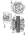
- a motion transmission device 10 contemplated by the present invention includes an involute-helicoidal screw 12 passing through, supporting, and threadedly engaging a nut assembly generally designated 14.
- a shaft 12 may be driven by any suitable power unit that is reversible (not shown) and the nut assembly 14 may be connected to a work load, carriage, or the like, to be moved along the axis of the shaft.
- the nut assembly 14 may be axially fixed but rotated under power and the shaft 12 moved axially relatively thereto and may be connected to the work load, carriage or the like.
- the shaft 12 is of the multiple lead of thread type.
- the preferred variety is a three lead thread of the right hand type but may be left or right handed as is best suited to a particular situation.
- a preferred form for such a screw thread on the shaft is that of an involute-helicoidal screw.
- the screw blank 12 and cutter (or grinding wheel) 16 are mounted in a standard thread-milling (or thread-grinding) machine geared to provide the desired lead.
- the axis 18 of the cutter 16 is set parallel to the axis 20 of the screw blank 12.
- the cutter 16 has a frusto-conical shape whose pressure angle is equal to the base helix angle of the involute-helicoid being generated. It can be shown mathematically that the finishing contact line 22 (a straight line) is located in a plane 24 containing the axis 18 of the cutter 16 and which is also tangent of the screw. In effect, the involute-helicoidal screw form is generated by the straight line segment 22. From the foregoing it is evident that the form of the screw depends only on the lead value and the pressure angle of the cutter, not on its size.
- This method of machining the screw lends itself well to forming multiple threads on the screw in a single pass, without indexing, since the cutter can have a multiplicity of forms equal in number to the number of starts desired to the screw (not shown).
- the nut assembly 14 includes an outer housing having a cylindrical shell 30 and a pair of end walls 32 suitably affixed to the shell 30 as by the bolts 34. It will be appreciated that, in a practical application of this device, means such as flanges or trunions would be included for association of the housing with the work-piece, carriage or the like.
- the screw 12 in the illustrated embodiment has three leads and hence the nut assembly includes three rollers 40 symmetrically disposed in circumferentially spaced relation around the screw 12.
- the rollers 40 have annular grooves and ridges and are conjugate to the screw threads 12.
- the rollers 40 are provided with a stub shaft or pintle 42 which is located within suitable anti-friction bearing means 44 position within a boss 46 supported by the end wall 32 of the housing.
- Encircling the rollers 40 is continuous ring 50 having internal grooves 52 that are conjugate to the ridges and grooves of roller 40. Adjacent the end surfaces, in this .embodiment, of the ring 50 there are provided suitable anti-friction bearing means such as ball bearings, roller bearings or tapered roller bearings 60 which transmit the forces that pass from the screw 12 to the annular roller 40 and the conjugate teeth 52 of the ring 50, thence through the bearings 60 into the housing 14.
- the outer nut assembly which engages the stub shafts 42, by means such as the bearing 44 may also utilize circumerentially disposed slots to permit slight movement of the rollers 40, but generally to prevent their planetary motion.
- rollers are in equilibrium between the screw and the ring and need no other support. It is evident that this device has a lead screw since the ring is prevented from axial motion by the fixed outer nut assembly that engages it through the anti-friction bearings 60.
- the small rolllers 40 are at all times in force- equilibrium between the screw 12 and the ring 50 except for the relatively small tangential forces resulting from the input driving torque. All the large axial forces are transmitted through substantially rolling contact, from the screw to the rollers (see force arrow "A"), from the rollers to the ring, and from the ring (see force arrow "B") through the bearings to the outer housing (see the arrow extending from ball bearing 60 into end wall 32.) The only coulomb friction within the device occurs at the stub shafts or pintles 42 and these are subject only to the input forces, which are of generally very small magnitude. The forces are evenly distributed since substantially all of the teeth (rings and grooves) or each roller are engaged by both the screw 12 and ring 50.
- the threaded shaft 12a is a multiple lead thread, in the present instance three leads, substantially identical to that utilized in the first embodiment.
- the nut assembly 14a includes an outer cylindrical shell 30a and a pair of end walls 32a having axially extending portions 70 which serve to form pockets for retention of the roller elements. In this instance the roller 40a is split into two axially spaced portions 72 and 74.
- the end wall 32a also includes additional axial extensions such as a shorter portion or pressure means 76 which limits the axial movement of the rollers while the semi-circular extension 70 symmetrically locate the shorter roller portions 72 and 74.
- the ring 50a is also divided into two portions 80 and 82 which are generally equal in axial extent to the roller portions 72 and 74 and with their outboard axial extremities bearing against anti-friction devices 60a that bear against the end walls 32a of the housing.
- a physical arrangement such as just described is modification of the first embodiment primarily for purposes to eliminate backlash as well as providing any desired degree of preload between the annular rollers 72-74 and the screw 12a.
- the rollers in the ring each have annular grooves and forces are transmitted to the outer nut housing through anti-friction bearings.
- the second embodiment has two rings and two sets of rollers contained in pockets extending from the end plates symmetrically to the middle.
- the end plates are tied together with the outer housing 30a in a way that permits a small relative angular displacement of one with respect to the other.
- the screw members 34 were used to retain the end plates 32 relative to the cylindrical shell 30a.
- the end wall 32a can be provided with a circumferentially disposed slot through which the screw 34a would be positioned and thereby permit angular rotation of one wall 32a with respect to the opposite end wall.
- the ring portions 80-82 are made suitably thin in a radial direction they will flex slightly in the radial direction, thus compensating for wear and preventing binding, while still retaining their stiffness in the axial direction to carry the loads required.
- rollers will be conjugate with an involute-helicoidal screw thread and can be adapted to accept small rollers, large rollers and intermediate size rollers with an appropriate diameter of annular grooved rings.
- Installation of the appropriate thrust bearings to accept the axially directed load ensures that virtually all of the forces being transmitted are of a rolling nature where the screw forces are passed to the rollers, from the rollers to the ring and from the ring through the thrust bearing means to the housing.
- the nut assembly is capable of being built into slides, or housings, and fastening means may be attached to the nut assembly housing for association with a work-piece (not shown).
Landscapes
- Engineering & Computer Science (AREA)
- General Engineering & Computer Science (AREA)
- Mechanical Engineering (AREA)
- Transmission Devices (AREA)
- Devices For Conveying Motion By Means Of Endless Flexible Members (AREA)
- Graft Or Block Polymers (AREA)
- Toilet Supplies (AREA)
- Braking Arrangements (AREA)
- Extrusion Moulding Of Plastics Or The Like (AREA)
- Fluid-Damping Devices (AREA)
- Gas-Filled Discharge Tubes (AREA)
- Holders For Apparel And Elements Relating To Apparel (AREA)
- Dowels (AREA)
- Glass Compositions (AREA)
Priority Applications (1)
| Application Number | Priority Date | Filing Date | Title |
|---|---|---|---|
| AT85304018T ATE36190T1 (de) | 1984-06-13 | 1985-06-06 | Zusammensetzen von mutter und gewindespindel. |
Applications Claiming Priority (2)
| Application Number | Priority Date | Filing Date | Title |
|---|---|---|---|
| US620355 | 1984-06-13 | ||
| US06/620,355 US4576057A (en) | 1984-06-13 | 1984-06-13 | Anti-friction nut/screw drive |
Publications (2)
| Publication Number | Publication Date |
|---|---|
| EP0168942A1 EP0168942A1 (en) | 1986-01-22 |
| EP0168942B1 true EP0168942B1 (en) | 1988-08-03 |
Family
ID=24485604
Family Applications (1)
| Application Number | Title | Priority Date | Filing Date |
|---|---|---|---|
| EP85304018A Expired EP0168942B1 (en) | 1984-06-13 | 1985-06-06 | Lead screw and nut assembly |
Country Status (10)
| Country | Link |
|---|---|
| US (1) | US4576057A (da) |
| EP (1) | EP0168942B1 (da) |
| JP (1) | JPH0621624B2 (da) |
| AT (1) | ATE36190T1 (da) |
| AU (1) | AU572630B2 (da) |
| BR (1) | BR8500971A (da) |
| CA (1) | CA1227953A (da) |
| DE (1) | DE3564153D1 (da) |
| DK (1) | DK159083C (da) |
| ES (1) | ES541369A0 (da) |
Families Citing this family (57)
| Publication number | Priority date | Publication date | Assignee | Title |
|---|---|---|---|---|
| US5027667A (en) * | 1984-01-30 | 1991-07-02 | Weyer Paul P | Spring actuator with rollers |
| US4945778A (en) * | 1984-01-30 | 1990-08-07 | Weyer Paul P | Fluid-power device with rollers |
| US4741250A (en) * | 1984-01-30 | 1988-05-03 | Weyer Paul P | Fluid-power device using rollers |
| US4881419A (en) * | 1984-01-30 | 1989-11-21 | Weyer Paul P | Fluid-power bearing actuator |
| US4846007A (en) * | 1986-07-03 | 1989-07-11 | Weyer Paul P | Fluid-power device using axially offset rollers |
| US4838103A (en) * | 1986-07-03 | 1989-06-13 | Weyer Paul P | Fluid-power device with rollers |
| US4702448A (en) * | 1986-02-03 | 1987-10-27 | Lojacono Francis X | Support bracket |
| EP0249674A1 (en) * | 1986-06-18 | 1987-12-23 | Bo Granbom | Device for converting a rotary motion into a linear one |
| US4748866A (en) * | 1986-07-03 | 1988-06-07 | Weyer Paul P | Linear helical actuator |
| JPH01127284A (ja) * | 1987-11-09 | 1989-05-19 | Hitachi Ltd | ロボットの動作制御装置 |
| US4964314A (en) * | 1989-03-13 | 1990-10-23 | Wilkes Donald F | Device for converting rotary motion to linear motion |
| US5004205A (en) * | 1990-06-04 | 1991-04-02 | Rockwell International Corporation | High-range and resolution determinate mount and positioner |
| US5491372A (en) * | 1991-10-11 | 1996-02-13 | Exlar Corporation | Electric linear actuator with planetary action |
| US5557154A (en) * | 1991-10-11 | 1996-09-17 | Exlar Corporation | Linear actuator with feedback position sensor device |
| JPH0550219U (ja) * | 1991-12-10 | 1993-07-02 | 欣一 小川 | 往復駆動装置 |
| US5809837A (en) * | 1994-05-02 | 1998-09-22 | Shaffer; James E. | Roller screw device for converting rotary to linear motion |
| US5551314A (en) * | 1994-08-24 | 1996-09-03 | Andrzejewski, Jr.; Max C. | Lead screw and linear drive assemblies using such lead screw |
| US6131479A (en) * | 1995-07-07 | 2000-10-17 | Dewitta Spezialmaschinenfabrik Wittenstein Gmbh & Co. Kg | Device for converting rotary motion into axial motion |
| DE19540634C1 (de) * | 1995-10-31 | 1997-03-13 | Deutsche Forsch Luft Raumfahrt | Vorrichtung zur Umwandlung einer Dreh- in eine Axialbewegung |
| DE19600238A1 (de) * | 1996-01-05 | 1997-07-10 | Dewitta Spezialmaschf | Vorrichtung zur Umwandlung einer Dreh- in eine Axialbewegung |
| US5707414A (en) * | 1996-02-07 | 1998-01-13 | Owens-Brockway Glass Container Inc. | Servo plunger mechanism |
| US6098479A (en) * | 1997-08-23 | 2000-08-08 | Hoermansdoerfer; Gerd | Linear actuator and preferred application |
| DE19650732A1 (de) * | 1996-12-06 | 1998-06-10 | Schaeffler Waelzlager Ohg | Vorrichtung zur Umwandlung einer Drehbewegung in eine geradlinige Bewegung |
| DE19747074A1 (de) * | 1997-10-24 | 1999-04-29 | Schaeffler Waelzlager Ohg | Lageranordnung |
| DE19750585A1 (de) * | 1997-11-17 | 1999-06-02 | Deutsch Zentr Luft & Raumfahrt | Aktuator zum Korrigieren eines über das Lenkrad eines Fahrzeugs an die Räder einer gelenkten Fahrzeugachse eingegebenen Lenkwinkels |
| JP2001208503A (ja) * | 2000-01-25 | 2001-08-03 | Harmonic Drive Syst Ind Co Ltd | リニアアクチュエータの絶対位置検出装置 |
| US6648568B2 (en) * | 2001-01-18 | 2003-11-18 | Utica Enterprises, Inc. | Linear blind broaching machine |
| GB0129350D0 (en) | 2001-12-07 | 2002-01-30 | Prec Actuation Systems Ltd | A device |
| FR2839127B1 (fr) * | 2002-04-24 | 2004-06-25 | Transrol | Dispositif d'actionnement a elements roulants intermediaires |
| JP3817677B2 (ja) * | 2003-05-30 | 2006-09-06 | 現代自動車株式会社 | 独立型ステアバイワイヤシステムのステアリングアクチュエータ |
| CN100585220C (zh) * | 2004-06-22 | 2010-01-27 | 杉谷伸 | 齿轮机构、行星齿轮装置、旋转轴承装置、及奇异行星齿轮减速装置 |
| AT502285B1 (de) * | 2004-10-19 | 2008-12-15 | Gissing Gerhard | Trennschleifring mit doppelter kernspannvorrichtung |
| JP4786240B2 (ja) | 2005-07-27 | 2011-10-05 | Ntn株式会社 | 電動式直動アクチュエータおよび電動式ブレーキ装置 |
| US20070266809A1 (en) * | 2006-05-18 | 2007-11-22 | Detlev Ziesel | Lift actuator and lift machine incorporating same |
| DE102006047790B4 (de) | 2006-10-06 | 2015-10-15 | Narr Beteiligungs Gmbh | Vorrichtung zur Umwandlung einer Drehbewegung in eine Axialbewegung |
| DE102008023130B3 (de) * | 2008-05-09 | 2009-12-31 | Eads Deutschland Gmbh | Vorrichtung zur Kontaktierung eines T/R-Moduls mit einer Testeinrichtung |
| KR101651675B1 (ko) | 2009-10-30 | 2016-08-29 | 유한킴벌리 주식회사 | 환형의 흡수부재를 구비하는 흡수제품 |
| JP5091958B2 (ja) * | 2010-01-26 | 2012-12-05 | 株式会社日立製作所 | 送りネジ装置、リニアアクチュエータ及びリフト装置 |
| JP5345587B2 (ja) * | 2010-06-15 | 2013-11-20 | 株式会社日立製作所 | 回転直動変換機構 |
| EP2581422A1 (en) | 2011-10-11 | 2013-04-17 | Sicpa Holding Sa | Ink coatings for security documents to prevent forgery by means of heat sensitive erasable ink |
| DE102011087712A1 (de) * | 2011-12-05 | 2013-06-06 | Schaeffler Technologies AG & Co. KG | Planetenwälzgewindetrieb |
| FR2984443B1 (fr) * | 2011-12-16 | 2014-01-17 | Skf Ab | Vis a rouleaux. |
| CN102562986A (zh) * | 2012-03-22 | 2012-07-11 | 上海久能机电制造有限公司 | 一种行星滚柱丝杠 |
| CN102678866A (zh) * | 2012-05-25 | 2012-09-19 | 西北工业大学 | 行星滚柱丝杠副 |
| WO2015081951A1 (de) * | 2013-12-06 | 2015-06-11 | Schaeffler Technologies AG & Co. KG | Aktuator mit planetenwälzgewindespindel (pwg) |
| KR102334152B1 (ko) * | 2014-02-06 | 2021-12-02 | 섀플러 테크놀로지스 아게 운트 코. 카게 | 유성 롤러 스핀들을 구비한 액추에이터 |
| FR3021085B1 (fr) * | 2014-05-16 | 2016-05-27 | Thales Sa | Dispositif de precharge pour un mecanisme de vis a rouleaux guide en rotation |
| ITRE20150029A1 (it) * | 2015-04-16 | 2016-10-16 | Ferrari Fabrizio | Autoveicolo con sistema di accesso laterale con portiera scorrevole a scomparsa |
| DE102015207642B4 (de) * | 2015-04-27 | 2017-07-06 | Schaeffler Technologies AG & Co. KG | Aktor mit Planetenwälzgewindetrieb |
| CN109791123B (zh) * | 2016-09-23 | 2021-05-07 | 株式会社日立高新技术 | 驱动螺杆装置、送液机构以及送液方法 |
| CN109386581B (zh) * | 2018-12-09 | 2024-01-23 | 扬州海通电子科技有限公司 | 一种细牙自锁型滚齿丝杠 |
| EP4543751B1 (fr) | 2022-06-22 | 2026-04-29 | Safran Aircraft Engines | Mécanisme de changement de pas avec dispositif de verrouillage de pas comprenant une vis à rouleaux satellites |
| FR3137062B1 (fr) | 2022-06-22 | 2024-05-17 | Safran Aircraft Engines | Mecanisme de changement de pas avec dispositif de verrouillage de pas comprenant une vis a rouleaux satellites |
| US12601272B2 (en) | 2022-06-22 | 2026-04-14 | Safran Aircraft Engines | Pitch change mechanism with an actuator surrounding a fluid transfer bearing |
| FR3141443B1 (fr) | 2022-10-28 | 2025-04-04 | Safran Aircraft Engines | Mécanisme de changement de pas avec vérin de commande et dispositif de verrouillage de pas hors des chambres du vérin |
| FR3141441B1 (fr) | 2022-10-28 | 2025-04-11 | Safran Aircraft Engines | Mécanisme de changement de pas à cinématique inversée |
| FR3141442B1 (fr) | 2022-10-28 | 2025-03-07 | Safran Aircraft Engines | Mécanisme de changement de pas avec dispositif de verrouillage de pas en porte-à-faux |
Family Cites Families (17)
| Publication number | Priority date | Publication date | Assignee | Title |
|---|---|---|---|---|
| US2488256A (en) * | 1944-03-07 | 1949-11-15 | Electrolux Corp | Ball bearing jack screw |
| US2938400A (en) * | 1956-02-02 | 1960-05-31 | John T Gondek | Screw thread |
| US3003362A (en) * | 1959-02-04 | 1961-10-10 | Anderson Co | Motion-transmitting device |
| US2951390A (en) * | 1959-09-21 | 1960-09-06 | Anderson Co | Motion-transmitting device |
| US3004445A (en) * | 1959-10-14 | 1961-10-17 | Zeiss Carl | Screw drive for measuring instruments |
| US3164029A (en) * | 1961-03-07 | 1965-01-05 | Anderson Co | Screw-nut device |
| FR1494173A (fr) * | 1966-07-20 | 1967-09-08 | Dba Sa | Perfectionnement aux systèmes vis-écrou à rouleaux |
| DE2112785A1 (de) * | 1970-03-17 | 1971-11-18 | Heidenstam Erik Johann Von Dip | Rollengeraet |
| SE357241B (da) * | 1972-04-25 | 1973-06-18 | Skf Ind Trading & Dev | |
| US3861226A (en) * | 1972-07-17 | 1975-01-21 | Richard B Stanley | Linear actuator |
| US3965761A (en) * | 1974-03-21 | 1976-06-29 | Stanley Richard B | Linear actuator |
| US4033194A (en) * | 1975-06-12 | 1977-07-05 | Stanley Richard B | Synchronized linear actuator |
| US4050319A (en) * | 1976-01-16 | 1977-09-27 | Stanley Richard B | Linear actuator |
| CA1058909A (en) * | 1976-05-03 | 1979-07-24 | Illinois Tool Works Inc. | Reversible rotary to linear motion converting device |
| US4048867A (en) * | 1976-06-01 | 1977-09-20 | Illinois Tool Works Inc. | Mechanical device converting rotary input to linear compression or stretching output with a high mechanical advantage |
| FR2368432A1 (fr) * | 1976-10-19 | 1978-05-19 | Nussbaum Kg Fertigungstechnik | Ecrou de levage a faible friction avec auto-enrayage |
| JPS5465262A (en) * | 1977-11-01 | 1979-05-25 | Shiyouichi Naruse | Instrument of supporting male screw for feed screw |
-
1984
- 1984-06-13 US US06/620,355 patent/US4576057A/en not_active Expired - Lifetime
-
1985
- 1985-03-04 BR BR8500971A patent/BR8500971A/pt unknown
- 1985-03-04 CA CA000475709A patent/CA1227953A/en not_active Expired
- 1985-03-12 AU AU39759/85A patent/AU572630B2/en not_active Expired
- 1985-03-18 ES ES541369A patent/ES541369A0/es active Granted
- 1985-06-06 AT AT85304018T patent/ATE36190T1/de not_active IP Right Cessation
- 1985-06-06 EP EP85304018A patent/EP0168942B1/en not_active Expired
- 1985-06-06 DE DE8585304018T patent/DE3564153D1/de not_active Expired
- 1985-06-07 JP JP60122855A patent/JPH0621624B2/ja not_active Expired - Lifetime
- 1985-06-13 DK DK267285A patent/DK159083C/da not_active IP Right Cessation
Also Published As
| Publication number | Publication date |
|---|---|
| ATE36190T1 (de) | 1988-08-15 |
| DE3564153D1 (en) | 1988-09-08 |
| DK267285A (da) | 1985-12-14 |
| AU572630B2 (en) | 1988-05-12 |
| EP0168942A1 (en) | 1986-01-22 |
| JPS612964A (ja) | 1986-01-08 |
| AU3975985A (en) | 1985-12-19 |
| JPH0621624B2 (ja) | 1994-03-23 |
| DK159083B (da) | 1990-08-27 |
| US4576057A (en) | 1986-03-18 |
| DK159083C (da) | 1991-02-18 |
| DK267285D0 (da) | 1985-06-13 |
| BR8500971A (pt) | 1986-04-15 |
| ES8603632A1 (es) | 1985-12-16 |
| ES541369A0 (es) | 1985-12-16 |
| CA1227953A (en) | 1987-10-13 |
Similar Documents
| Publication | Publication Date | Title |
|---|---|---|
| EP0168942B1 (en) | Lead screw and nut assembly | |
| EP0090214B1 (en) | Epicyclic transmission having free rolling roller driving elements | |
| EP1362198B1 (en) | Planet gear and use thereof | |
| US4487091A (en) | Speed reducer and method for reducing blacklash | |
| EP0189421B1 (en) | Power transmission system | |
| JPH0228027B2 (da) | ||
| US4541305A (en) | Speed reducer | |
| EP0003793B1 (en) | Planetary-roller transmission with elastic roller or ring | |
| GB2111635A (en) | A device for converting a rotary motion to a linear movement | |
| CA1280008C (en) | Fluid-power device with rollers | |
| US4563915A (en) | Wobble type axial speed reducer apparatus | |
| US5025671A (en) | High ratio planetary type traction roller transmission | |
| US3367198A (en) | Variable speed reducer mechanism | |
| NL8002267A (nl) | Werkwijze en inrichting voor het mechanisch over- brengen van kracht. | |
| CN113007313B (zh) | 一种高效啮合蜗轮 | |
| US5961221A (en) | Cross roller bearing and coriolis gear device | |
| EP0302846A1 (en) | Ball screw | |
| US4440043A (en) | Fixed ratio traction roller transmission with tapered loading means | |
| US4620455A (en) | Traction roller transmission | |
| CN114370487B (zh) | 谐波减速器及传动装置 | |
| EP0114561A1 (en) | Motion transmitting system | |
| EP0105370A4 (en) | GEAR WHEEL SET HAVING AN INTERNAL GEAR MECHANISM. | |
| GB2114259A (en) | Gearing | |
| JPH04272550A (ja) | 遊星ローラ式摩擦伝動装置 | |
| JPS60136659A (ja) | 減速機 |
Legal Events
| Date | Code | Title | Description |
|---|---|---|---|
| PUAI | Public reference made under article 153(3) epc to a published international application that has entered the european phase |
Free format text: ORIGINAL CODE: 0009012 |
|
| AK | Designated contracting states |
Designated state(s): AT BE CH DE FR GB IT LI NL SE |
|
| 17P | Request for examination filed |
Effective date: 19860701 |
|
| 17Q | First examination report despatched |
Effective date: 19870723 |
|
| GRAA | (expected) grant |
Free format text: ORIGINAL CODE: 0009210 |
|
| AK | Designated contracting states |
Kind code of ref document: B1 Designated state(s): AT BE CH DE FR GB IT LI NL SE |
|
| REF | Corresponds to: |
Ref document number: 36190 Country of ref document: AT Date of ref document: 19880815 Kind code of ref document: T |
|
| REF | Corresponds to: |
Ref document number: 3564153 Country of ref document: DE Date of ref document: 19880908 |
|
| ITF | It: translation for a ep patent filed | ||
| ET | Fr: translation filed | ||
| PLBE | No opposition filed within time limit |
Free format text: ORIGINAL CODE: 0009261 |
|
| STAA | Information on the status of an ep patent application or granted ep patent |
Free format text: STATUS: NO OPPOSITION FILED WITHIN TIME LIMIT |
|
| 26N | No opposition filed | ||
| ITTA | It: last paid annual fee | ||
| REG | Reference to a national code |
Ref country code: GB Ref legal event code: 732E |
|
| EAL | Se: european patent in force in sweden |
Ref document number: 85304018.6 |
|
| PGFP | Annual fee paid to national office [announced via postgrant information from national office to epo] |
Ref country code: AT Payment date: 20010521 Year of fee payment: 17 |
|
| REG | Reference to a national code |
Ref country code: GB Ref legal event code: IF02 |
|
| PG25 | Lapsed in a contracting state [announced via postgrant information from national office to epo] |
Ref country code: AT Free format text: LAPSE BECAUSE OF NON-PAYMENT OF DUE FEES Effective date: 20020606 |
|
| PGFP | Annual fee paid to national office [announced via postgrant information from national office to epo] |
Ref country code: NL Payment date: 20040517 Year of fee payment: 20 |
|
| PGFP | Annual fee paid to national office [announced via postgrant information from national office to epo] |
Ref country code: GB Payment date: 20040602 Year of fee payment: 20 |
|
| PGFP | Annual fee paid to national office [announced via postgrant information from national office to epo] |
Ref country code: FR Payment date: 20040618 Year of fee payment: 20 |
|
| PGFP | Annual fee paid to national office [announced via postgrant information from national office to epo] |
Ref country code: SE Payment date: 20040621 Year of fee payment: 20 Ref country code: CH Payment date: 20040621 Year of fee payment: 20 |
|
| PGFP | Annual fee paid to national office [announced via postgrant information from national office to epo] |
Ref country code: BE Payment date: 20040715 Year of fee payment: 20 |
|
| PGFP | Annual fee paid to national office [announced via postgrant information from national office to epo] |
Ref country code: DE Payment date: 20040802 Year of fee payment: 20 |
|
| PG25 | Lapsed in a contracting state [announced via postgrant information from national office to epo] |
Ref country code: GB Free format text: LAPSE BECAUSE OF EXPIRATION OF PROTECTION Effective date: 20050605 |
|
| PG25 | Lapsed in a contracting state [announced via postgrant information from national office to epo] |
Ref country code: NL Free format text: LAPSE BECAUSE OF EXPIRATION OF PROTECTION Effective date: 20050606 |
|
| REG | Reference to a national code |
Ref country code: GB Ref legal event code: PE20 |
|
| BE20 | Be: patent expired |
Owner name: *ILLINOIS TOOL WORKS INC. Effective date: 20050606 |
|
| REG | Reference to a national code |
Ref country code: CH Ref legal event code: PL |
|
| NLV7 | Nl: ceased due to reaching the maximum lifetime of a patent |
Effective date: 20050606 |
|
| EUG | Se: european patent has lapsed | ||
| BE20 | Be: patent expired |
Owner name: *ILLINOIS TOOL WORKS INC. Effective date: 20050606 |