EP0168053B1 - Auskleidung von Pipelines und Durchgängen - Google Patents
Auskleidung von Pipelines und Durchgängen Download PDFInfo
- Publication number
- EP0168053B1 EP0168053B1 EP85108645A EP85108645A EP0168053B1 EP 0168053 B1 EP0168053 B1 EP 0168053B1 EP 85108645 A EP85108645 A EP 85108645A EP 85108645 A EP85108645 A EP 85108645A EP 0168053 B1 EP0168053 B1 EP 0168053B1
- Authority
- EP
- European Patent Office
- Prior art keywords
- lining
- passageway
- light
- pipeline
- resin
- Prior art date
- Legal status (The legal status is an assumption and is not a legal conclusion. Google has not performed a legal analysis and makes no representation as to the accuracy of the status listed.)
- Expired
Links
- XLYOFNOQVPJJNP-UHFFFAOYSA-N water Substances O XLYOFNOQVPJJNP-UHFFFAOYSA-N 0.000 claims abstract description 14
- 229910001507 metal halide Inorganic materials 0.000 claims abstract description 4
- 150000005309 metal halides Chemical class 0.000 claims abstract description 4
- 229920003002 synthetic resin Polymers 0.000 claims abstract description 4
- 239000000057 synthetic resin Substances 0.000 claims abstract description 4
- 229920005989 resin Polymers 0.000 claims description 34
- 239000011347 resin Substances 0.000 claims description 34
- 238000000034 method Methods 0.000 claims description 20
- 239000012530 fluid Substances 0.000 claims description 9
- 239000000463 material Substances 0.000 claims description 7
- 230000002745 absorbent Effects 0.000 claims description 6
- 239000002250 absorbent Substances 0.000 claims description 6
- 239000012528 membrane Substances 0.000 claims description 5
- 230000000694 effects Effects 0.000 claims description 4
- 238000007789 sealing Methods 0.000 claims description 4
- 230000008878 coupling Effects 0.000 claims 1
- 238000010168 coupling process Methods 0.000 claims 1
- 238000005859 coupling reaction Methods 0.000 claims 1
- IJGRMHOSHXDMSA-UHFFFAOYSA-N Atomic nitrogen Chemical compound N#N IJGRMHOSHXDMSA-UHFFFAOYSA-N 0.000 abstract description 4
- 229910052751 metal Inorganic materials 0.000 abstract description 3
- 239000002184 metal Substances 0.000 abstract description 3
- 229910052757 nitrogen Inorganic materials 0.000 abstract description 2
- 230000000712 assembly Effects 0.000 description 7
- 238000000429 assembly Methods 0.000 description 7
- 239000004020 conductor Substances 0.000 description 3
- 239000003999 initiator Substances 0.000 description 3
- 238000005286 illumination Methods 0.000 description 2
- 239000007788 liquid Substances 0.000 description 2
- 229920001225 polyester resin Polymers 0.000 description 2
- 239000004645 polyester resin Substances 0.000 description 2
- 239000004743 Polypropylene Substances 0.000 description 1
- NIXOWILDQLNWCW-UHFFFAOYSA-N acrylic acid group Chemical group C(C=C)(=O)O NIXOWILDQLNWCW-UHFFFAOYSA-N 0.000 description 1
- 239000004411 aluminium Substances 0.000 description 1
- 229910052782 aluminium Inorganic materials 0.000 description 1
- XAGFODPZIPBFFR-UHFFFAOYSA-N aluminium Chemical compound [Al] XAGFODPZIPBFFR-UHFFFAOYSA-N 0.000 description 1
- 238000005266 casting Methods 0.000 description 1
- 239000011248 coating agent Substances 0.000 description 1
- 238000000576 coating method Methods 0.000 description 1
- 150000001875 compounds Chemical class 0.000 description 1
- 239000002657 fibrous material Substances 0.000 description 1
- 239000011521 glass Substances 0.000 description 1
- 238000003780 insertion Methods 0.000 description 1
- 230000037431 insertion Effects 0.000 description 1
- 239000000314 lubricant Substances 0.000 description 1
- 239000000203 mixture Substances 0.000 description 1
- 238000010422 painting Methods 0.000 description 1
- -1 polypropylene Polymers 0.000 description 1
- 229920001155 polypropylene Polymers 0.000 description 1
- 230000001681 protective effect Effects 0.000 description 1
- 239000010453 quartz Substances 0.000 description 1
- 230000000452 restraining effect Effects 0.000 description 1
- VYPSYNLAJGMNEJ-UHFFFAOYSA-N silicon dioxide Inorganic materials O=[Si]=O VYPSYNLAJGMNEJ-UHFFFAOYSA-N 0.000 description 1
- 239000007921 spray Substances 0.000 description 1
- 238000005507 spraying Methods 0.000 description 1
Images

Classifications
-
- B—PERFORMING OPERATIONS; TRANSPORTING
- B29—WORKING OF PLASTICS; WORKING OF SUBSTANCES IN A PLASTIC STATE IN GENERAL
- B29C—SHAPING OR JOINING OF PLASTICS; SHAPING OF MATERIAL IN A PLASTIC STATE, NOT OTHERWISE PROVIDED FOR; AFTER-TREATMENT OF THE SHAPED PRODUCTS, e.g. REPAIRING
- B29C35/00—Heating, cooling or curing, e.g. crosslinking or vulcanising; Apparatus therefor
- B29C35/02—Heating or curing, e.g. crosslinking or vulcanizing during moulding, e.g. in a mould
- B29C35/08—Heating or curing, e.g. crosslinking or vulcanizing during moulding, e.g. in a mould by wave energy or particle radiation
- B29C35/10—Heating or curing, e.g. crosslinking or vulcanizing during moulding, e.g. in a mould by wave energy or particle radiation for articles of indefinite length
-
- B—PERFORMING OPERATIONS; TRANSPORTING
- B29—WORKING OF PLASTICS; WORKING OF SUBSTANCES IN A PLASTIC STATE IN GENERAL
- B29C—SHAPING OR JOINING OF PLASTICS; SHAPING OF MATERIAL IN A PLASTIC STATE, NOT OTHERWISE PROVIDED FOR; AFTER-TREATMENT OF THE SHAPED PRODUCTS, e.g. REPAIRING
- B29C63/00—Lining or sheathing, i.e. applying preformed layers or sheathings of plastics; Apparatus therefor
- B29C63/0065—Heat treatment
- B29C63/0069—Heat treatment of tubular articles
-
- B—PERFORMING OPERATIONS; TRANSPORTING
- B29—WORKING OF PLASTICS; WORKING OF SUBSTANCES IN A PLASTIC STATE IN GENERAL
- B29C—SHAPING OR JOINING OF PLASTICS; SHAPING OF MATERIAL IN A PLASTIC STATE, NOT OTHERWISE PROVIDED FOR; AFTER-TREATMENT OF THE SHAPED PRODUCTS, e.g. REPAIRING
- B29C63/00—Lining or sheathing, i.e. applying preformed layers or sheathings of plastics; Apparatus therefor
- B29C63/26—Lining or sheathing of internal surfaces
- B29C63/34—Lining or sheathing of internal surfaces using tubular layers or sheathings
- B29C63/36—Lining or sheathing of internal surfaces using tubular layers or sheathings being turned inside out
-
- F—MECHANICAL ENGINEERING; LIGHTING; HEATING; WEAPONS; BLASTING
- F16—ENGINEERING ELEMENTS AND UNITS; GENERAL MEASURES FOR PRODUCING AND MAINTAINING EFFECTIVE FUNCTIONING OF MACHINES OR INSTALLATIONS; THERMAL INSULATION IN GENERAL
- F16L—PIPES; JOINTS OR FITTINGS FOR PIPES; SUPPORTS FOR PIPES, CABLES OR PROTECTIVE TUBING; MEANS FOR THERMAL INSULATION IN GENERAL
- F16L55/00—Devices or appurtenances for use in, or in connection with, pipes or pipe systems
- F16L55/16—Devices for covering leaks in pipes or hoses, e.g. hose-menders
- F16L55/162—Devices for covering leaks in pipes or hoses, e.g. hose-menders from inside the pipe
- F16L55/165—Devices for covering leaks in pipes or hoses, e.g. hose-menders from inside the pipe a pipe or flexible liner being inserted in the damaged section
- F16L55/1651—Devices for covering leaks in pipes or hoses, e.g. hose-menders from inside the pipe a pipe or flexible liner being inserted in the damaged section the flexible liner being everted
-
- H—ELECTRICITY
- H01—ELECTRIC ELEMENTS
- H01J—ELECTRIC DISCHARGE TUBES OR DISCHARGE LAMPS
- H01J61/00—Gas-discharge or vapour-discharge lamps
- H01J61/02—Details
- H01J61/30—Vessels; Containers
- H01J61/34—Double-wall vessels or containers
-
- B—PERFORMING OPERATIONS; TRANSPORTING
- B29—WORKING OF PLASTICS; WORKING OF SUBSTANCES IN A PLASTIC STATE IN GENERAL
- B29C—SHAPING OR JOINING OF PLASTICS; SHAPING OF MATERIAL IN A PLASTIC STATE, NOT OTHERWISE PROVIDED FOR; AFTER-TREATMENT OF THE SHAPED PRODUCTS, e.g. REPAIRING
- B29C35/00—Heating, cooling or curing, e.g. crosslinking or vulcanising; Apparatus therefor
- B29C35/02—Heating or curing, e.g. crosslinking or vulcanizing during moulding, e.g. in a mould
- B29C35/08—Heating or curing, e.g. crosslinking or vulcanizing during moulding, e.g. in a mould by wave energy or particle radiation
- B29C35/0805—Heating or curing, e.g. crosslinking or vulcanizing during moulding, e.g. in a mould by wave energy or particle radiation using electromagnetic radiation
- B29C2035/0833—Heating or curing, e.g. crosslinking or vulcanizing during moulding, e.g. in a mould by wave energy or particle radiation using electromagnetic radiation using actinic light
-
- B—PERFORMING OPERATIONS; TRANSPORTING
- B29—WORKING OF PLASTICS; WORKING OF SUBSTANCES IN A PLASTIC STATE IN GENERAL
- B29C—SHAPING OR JOINING OF PLASTICS; SHAPING OF MATERIAL IN A PLASTIC STATE, NOT OTHERWISE PROVIDED FOR; AFTER-TREATMENT OF THE SHAPED PRODUCTS, e.g. REPAIRING
- B29C35/00—Heating, cooling or curing, e.g. crosslinking or vulcanising; Apparatus therefor
- B29C35/02—Heating or curing, e.g. crosslinking or vulcanizing during moulding, e.g. in a mould
- B29C35/08—Heating or curing, e.g. crosslinking or vulcanizing during moulding, e.g. in a mould by wave energy or particle radiation
-
- B—PERFORMING OPERATIONS; TRANSPORTING
- B29—WORKING OF PLASTICS; WORKING OF SUBSTANCES IN A PLASTIC STATE IN GENERAL
- B29K—INDEXING SCHEME ASSOCIATED WITH SUBCLASSES B29B, B29C OR B29D, RELATING TO MOULDING MATERIALS OR TO MATERIALS FOR MOULDS, REINFORCEMENTS, FILLERS OR PREFORMED PARTS, e.g. INSERTS
- B29K2105/00—Condition, form or state of moulded material or of the material to be shaped
- B29K2105/06—Condition, form or state of moulded material or of the material to be shaped containing reinforcements, fillers or inserts
-
- B—PERFORMING OPERATIONS; TRANSPORTING
- B29—WORKING OF PLASTICS; WORKING OF SUBSTANCES IN A PLASTIC STATE IN GENERAL
- B29K—INDEXING SCHEME ASSOCIATED WITH SUBCLASSES B29B, B29C OR B29D, RELATING TO MOULDING MATERIALS OR TO MATERIALS FOR MOULDS, REINFORCEMENTS, FILLERS OR PREFORMED PARTS, e.g. INSERTS
- B29K2105/00—Condition, form or state of moulded material or of the material to be shaped
- B29K2105/24—Condition, form or state of moulded material or of the material to be shaped crosslinked or vulcanised
Definitions
- This invention relates to the lining of pipelines or passageways with a tubular liner and a curable synthetic resin.
- a method of lining a pipeline or passageway comprising moving a flexible tubular lining into the pipeline or passageway and using a fluid pressure differential to shape the tubular lining to the passageway surface, there being a light curable synthetic resin sandwiched between the inner surface of the lining and the passageway surface to define a hard pipe lining the passageway surface when cured, characterised in that a means is attached to the lining tube, when it is moved into the pipeline or passageway enabling curing light source means to be pulled into the passageway in order to effect curing of the resin.
- the lining may comprise one or more layers of resin absorbent material such as fibrous felet which is or are impregnated with the resin, and the resin may be applied to the resin absorbent material layer or layers inside or outside the passageway.
- resin absorbent material such as fibrous felet which is or are impregnated with the resin
- the resin may be applied to the passageway surface and may be held thereto by the subsequent application of the tubular liner, which may be in the form of a thin tubular membrane, inverted into the passageway imme- diatelyfollowing the application of the resin to the passageway surface.
- the application of the resin to the passageway surface may be by any suitable means, such as spraying or painting.
- the lining may be simply pulled into the passageway and then inflated using the fluid pressure differential or it may be inverted by said fluid pressure differential into and along the passageway.
- the fluid pressure differential may be created by liquid and/or gaseous medium as required.
- the said means may comprise a rope cable or the like which is attached to one end of the lining and which can be used for applying a restraining effect on the end of the lining when the lining is inverted, or in an alternative arrangement, to the end of the lining is attached a pulley forming said means, and the hold back rope trains round the pulley to provide two operative reaches of the rope.
- the rope is pulled round the pulley so that one reach is removed from the passageway, and the other reach feeds round the pulley.
- the light source means may be kept in position essentially centrally of the passageway by means of ballast weights and/or floats or any other suitable means.
- the light source means may comprise one or more light source units comprising high intensity filaments located in a vacuum casing, the casing being contained in a protective and transparent outer casing, the units being sealed permitting the light source means to be used under water.
- the lights may be high pressure metal halide lamps having pinched ends and they may be a wavelength of the order of 350 to 450 nanometres.
- the lining In the majority of cases, where the lining is everted, it will be everted using water, but in some cases the lining is everted by air or a combination of air and water. Where air only is used, in accordance with another of our inventions, it is preferred that a lubricant be placed in the base of the passageway to enable the lining to slip over same.
- a pull through cord, tape or the like which is located in the inside of the lining prior to inversion, so that the cord emerges from the inversion face, and tension can be applied thereto in order to assist the inversion process as necessary.
- the lining preferably comprises before insertion in the passageway one or more layers of fibrous felt, with the outside of the layer or the outside of the outermost layer provided with a fluid impermeable coating.
- the fibres of the felt and the resin are preferably selected so that they have a combined refractive index making the combined material substantially transparent to the specific wave length light which isused for the curing process whereby the light will penetrate completely through the lining in order to effect cure through the entire thickness of the lining.
- the lining may be any thickness but typically will be between 2 mm and 25 mm.
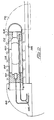
- FIG. 1 in this figure is shown an underground pipe 10 which is in the process of being lined with a liner 12 of flexible material.
- the pipe 10 is located under the ground level 14, and the liner is being inserted through a manhole 16, by means of an elbow feeding pipe 18.
- An end 20 of the liner is fixed to the open end of the elbow pipe 18 located in the bottom of the manhole, and then water is poured into the elbow pipe 18 as indicated by the spout 22, so as to cause the liner 12 to evert into and along the inside of the pipe 10, as illusrated at the everting region 24.
- the trailing end of the liner is illustrated at point 26, and the liner feed is maintained by keeping a constant head 28 of water in the elbow pipe 18.
- the liner 12 is made up of a layer 30 which is of resin absorbent material such as fibrous material in woven or felted form, or in any suitable combination, and an inner membrane 32 which is impermeable to fluids.
- the layer 30 is impregnated with a curable resin material, such as polyester resin or the like, and it will be observed that initially the membrane 32 is to the outside of the liner before inversion as shown in the region 34, but becomes the inner layer after the lining is applied to the inside of the pipe 10, and to resin lies between the inner surface of the liner and the passageway surface.
- the lining which is flexible until the resin carried thereby is cured is tailored to the size of the pipe 10 to be lined, and the trailing end 26 eventually emerges in another manhole, similar to manhole 16 but spaced therefrom, and after curing the protruding end is cut off to complete the lining operation.
- a first rope or cable 36 is a "pull through” rope which can be used to help to pull through the everting portion of the liner in the event of need, whilst the other rope or cable' 38 is a “hold back” rope which is attached to the point 36, and is trained round a guide roller 40 in the elbow 18, and serves to prevent the trailing end 26 of the liner from travelling along the inside of the passageway too quickly.
- the resin which impregnates the layer 30 contains a photo-initiator so that the resin system as a whole will be light curing, and in the arrangement shown in Fig. 1 a bank of illumination source assemblies 40, 42 and 44 are connected in the hold back rope 38, these sources being maintained at least approximately centrally of the pipe 10 by means of ballasting weights 46.
- a bank of illumination source assemblies 40, 42 and 44 are connected in the hold back rope 38, these sources being maintained at least approximately centrally of the pipe 10 by means of ballasting weights 46.
- the resin system and the photo initiator are preferably chosen so that only certain wave lengths will initate the cure, and it is also desirable to choose the layer 30 to be of fibres which, when immersed in the resin system, provide a layer which is of a refractive index so that the layer is in fact substantially transparent to the light of those wave lengths which can initiate the cure. This is to ensure that the light will penetrate through the interior thickness of the layer 30 to give effective curing.
- the membrane 32 is also selected to be transparent to light up the aforesaid wave lengths.
- the hold back rope 38 which may be a multicore cable will incorporate all of the necessary electrical conductors and ignitors for controlling and powering the bank assemblies 40, 42 and 44. As soon as the lamps (when lit) start travelling along the inside of the pipeline, the resin systems start to cure. The speed of inversion of the lining is controlled so that full and even curing takes place.
- Figures 3 and 4 illustrate an alternative method for a lining operation, but parts already described have the same reference numerals.
- the trailirig end 26 of the lining 12 is attached the pulley 50, and trained round the pulley is the pull back cable 38 defining two reaches 38A and 38B. These two reaches control the inward inversion of the lining, but at the end of the inversion, as shown in Fig. 4 the reaches are fed round the pulley 50, and attached to the end of one reach is the bank of light assemblies 40, 42 and 44, so that in fact these assemblies (when lit) are pulled through at a controlled speed after the eversion process has been completed.
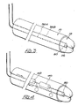
- Fig. 2 shows one arrangement which has been found suitable for each light unit, and referring to Fig. 2 a light unit is shown in sectional elevation.
- This is a high intensity metal halide lamp which provides a convenient light source, Because such a lamp requires a high operating temperature it is protected from the water by sealing the lamp in an outer tube of glass or quartz, and appropriate provision is made to conduct heat from the ends of the lamp as it must be kept relatively cool.
- the lamp is indicated by numeral 60 and is mounted by its ends within metal mounting blocks 62.
- These blocks are of metal such as aluminium in order to serve not only as conductors but also as heat drains to drain heat away from the lamp 60.
- the electric conductors 66 of the lamp 60 pass through a connector 68 which sealingly receives the screwed end of an outer transparent tube 72 which is optionally protected by a wire screen 74 and which is nitrogen filled.
- the screen is made up of individual strands which extend helically relative to the casing 72 in order to avoid the casting of linear shadows on the pipeline as the light assemblies pass down the inside of the liner during the curing operation.
- the casing 72 is a closed end tube and the closed end may, as shown in dotted lines, be supported by a mounting 76.
- the mountings 68 and 76 have the shape shown to protect the lamp assembly from being impacted as it is being drawn into and out of the passageway.
- the mounting 68 will be filled with sealing compound to waterproof the connecting lead 66 which couple with the multicore cable 38.
- the lining comprises resin absorbent felt layers, which may be of acrylic or polypropylene fibres, and the tube is dimensioned to the size of the passageway to be lined, so that it will experience a minimum stretch.
- resin absorbent felt layers which may be of acrylic or polypropylene fibres
- the tube is dimensioned to the size of the passageway to be lined, so that it will experience a minimum stretch.
- flexible tubes which are stretchable or non-stretchable.
- the flexible tubes forming linings may be simply pulled into the pipeline or passageway and then inflated herein fluid pressure of air or water or a combination of air and water.
- the resin may be applied to the absorbent layers either before the lining is introduced into the passageway or after it has been introduced into the passageway and indeed as it is being applied to the passageway surface.
- a layer of the curable resin is applied to the passageway surface for example by a rotary spray or the like, and this is followed immediately by an everting flexible tubular liner which retains the resin in position lining the surface until it is cured by the lights as described herein.
- a suitable light curing resin which can be used in the process of the present invention is a polyester resin including photo initiator.
- the total energy required for curing is of the order of 1 % of that required when curing is achieved by inserting hot water into the inside of the everted liner.
Landscapes
- Engineering & Computer Science (AREA)
- Physics & Mathematics (AREA)
- Manufacturing & Machinery (AREA)
- General Engineering & Computer Science (AREA)
- Health & Medical Sciences (AREA)
- Thermal Sciences (AREA)
- Mechanical Engineering (AREA)
- Oral & Maxillofacial Surgery (AREA)
- Toxicology (AREA)
- Lining Or Joining Of Plastics Or The Like (AREA)
- Pipe Accessories (AREA)
- Pipeline Systems (AREA)
- Protection Of Pipes Against Damage, Friction, And Corrosion (AREA)
- Rigid Pipes And Flexible Pipes (AREA)
- Extrusion Moulding Of Plastics Or The Like (AREA)
Claims (10)
Priority Applications (1)
| Application Number | Priority Date | Filing Date | Title |
|---|---|---|---|
| AT85108645T ATE46023T1 (de) | 1984-07-16 | 1985-07-11 | Auskleidung von pipelines und durchgaengen. |
Applications Claiming Priority (2)
| Application Number | Priority Date | Filing Date | Title |
|---|---|---|---|
| GB8418038 | 1984-07-13 | ||
| GB848418038A GB8418038D0 (en) | 1984-07-16 | 1984-07-16 | Lining of pipelines/passageways |
Related Child Applications (2)
| Application Number | Title | Priority Date | Filing Date |
|---|---|---|---|
| EP88100439A Division EP0275924A3 (de) | 1984-07-13 | 1985-07-11 | Auskleidung von Pipelines und Durchgängen |
| EP88100439.4 Division-Into | 1985-07-11 |
Publications (3)
| Publication Number | Publication Date |
|---|---|
| EP0168053A2 EP0168053A2 (de) | 1986-01-15 |
| EP0168053A3 EP0168053A3 (en) | 1987-05-27 |
| EP0168053B1 true EP0168053B1 (de) | 1989-08-30 |
Family
ID=10563937
Family Applications (2)
| Application Number | Title | Priority Date | Filing Date |
|---|---|---|---|
| EP88100439A Withdrawn EP0275924A3 (de) | 1984-07-13 | 1985-07-11 | Auskleidung von Pipelines und Durchgängen |
| EP85108645A Expired EP0168053B1 (de) | 1984-07-13 | 1985-07-11 | Auskleidung von Pipelines und Durchgängen |
Family Applications Before (1)
| Application Number | Title | Priority Date | Filing Date |
|---|---|---|---|
| EP88100439A Withdrawn EP0275924A3 (de) | 1984-07-13 | 1985-07-11 | Auskleidung von Pipelines und Durchgängen |
Country Status (7)
| Country | Link |
|---|---|
| US (1) | US4680066A (de) |
| EP (2) | EP0275924A3 (de) |
| AT (1) | ATE46023T1 (de) |
| CY (1) | CY1583A (de) |
| DE (1) | DE3572717D1 (de) |
| GB (1) | GB8418038D0 (de) |
| HK (1) | HK8292A (de) |
Cited By (2)
| Publication number | Priority date | Publication date | Assignee | Title |
|---|---|---|---|---|
| US5653555A (en) | 1995-05-19 | 1997-08-05 | Inliner, U.S.A. | Multiple resin system for rehabilitating pipe |
| US5699838A (en) | 1995-05-22 | 1997-12-23 | Inliner, U.S.A. | Apparatus for vacuum impregnation of a flexible, hollow tube |
Families Citing this family (53)
| Publication number | Priority date | Publication date | Assignee | Title |
|---|---|---|---|---|
| GB8530720D0 (en) * | 1985-12-13 | 1986-01-22 | Bio Kil Chemicals Ltd | Applying protective coating |
| DE3546417A1 (de) * | 1985-12-31 | 1987-07-16 | Rolining Ag | Verfahren und vorrichtung zur sanierung insbesondere erdverlegter rohrleitungen |
| GB2197253B (en) * | 1986-11-14 | 1990-08-22 | Bcl Ltd | Multilayer carrier films |
| EP0275060A1 (de) * | 1987-01-14 | 1988-07-20 | Insituform International Inc. | Auskleidung von Pipelines und Durchgängen |
| CH673695A5 (en) * | 1987-07-29 | 1990-03-30 | Lorenz Haller | Repairing e.g. PVC pipe |
| EP0301204B1 (de) * | 1987-07-29 | 1991-09-18 | SOFTLINING AG Systems for Relining | Schlauch für die Innenerneuerung von Rohrleitungen und Verwendung desselben |
| US5106440A (en) * | 1989-01-30 | 1992-04-21 | Tangeman Andrew F | Method for repairing manholes or wetwalls |
| GB8904475D0 (en) * | 1989-02-28 | 1989-04-12 | Pipe & Sewer Renovations Limit | Rubber compositions |
| SE9100524D0 (sv) * | 1991-02-22 | 1991-02-22 | Inpipe Sweden Ab | Matare |
| SE9100870D0 (sv) * | 1991-03-22 | 1991-03-22 | Inpipe Sweden Ab | Foerfarande och anordning foer infodring av en helt eller delvis vaeggomsluten passage |
| AU2184992A (en) * | 1991-05-21 | 1992-12-30 | Sonic-Curing Inc. | Ultrasonically cured replacement pipe and method of installation |
| US5451351A (en) * | 1991-09-13 | 1995-09-19 | Composite Components, Inc. | Method for rehabilitating a pipe with a liner having an electrically conductive layer |
| US5322653A (en) * | 1992-06-05 | 1994-06-21 | Mueller Hans | Method of repairing buried sewage pipes |
| US5348764A (en) * | 1992-10-06 | 1994-09-20 | Yasuhiro Yokoshima | Method for impregnating a lining material with a hardenable resin |
| GB9313901D0 (en) * | 1993-07-06 | 1993-08-18 | Chandler Brian | Linings for pipelines and passageways |
| CA2168756C (en) * | 1993-08-06 | 2004-12-07 | Joachim Brandenburger | A method and apparatus of producing a tubular lining hose |
| GB9319832D0 (en) * | 1993-09-25 | 1993-11-10 | Insituform Technologies Inc | Improvements relating to the lining of pipelines and passageways |
| US5466093A (en) * | 1994-05-16 | 1995-11-14 | Keller; Carl E. | Method and apparatus for removing contaminants from a duct or pipe |
| DE4427969C2 (de) * | 1994-08-09 | 1998-05-14 | Teerbau Gmbh Strassenbau | Vorrichtung zur Aushärtung von Kunststoffauskleidungen |
| US5950682A (en) * | 1994-08-19 | 1999-09-14 | Lmk Enterprises, Inc. | Apparatus and method for repairing the junction of a sewer main line and lateral |
| JP2667796B2 (ja) * | 1995-07-07 | 1997-10-27 | 株式会社湘南合成樹脂製作所 | 管ライニング工法 |
| US5803666A (en) * | 1996-12-19 | 1998-09-08 | Keller; Carl E. | Horizontal drilling method and apparatus |
| US5853049A (en) * | 1997-02-26 | 1998-12-29 | Keller; Carl E. | Horizontal drilling method and apparatus |
| US5816345A (en) * | 1997-04-17 | 1998-10-06 | Keller; Carl E. | Horizontal drilling apparatus |
| US5915419A (en) * | 1997-11-26 | 1999-06-29 | Insituform (Netherlands) B.V. | Cured in place lateral seal for relining of pipelines and method of manufacture |
| US6068725A (en) * | 1997-11-26 | 2000-05-30 | Insituform (Netherlands) B.V. | Method of installation of a flexible cured in place lateral seal in an existing main pipeline |
| US6029726A (en) | 1997-11-26 | 2000-02-29 | Insituform (Netherlands) B.V. | Apparatus for installing a flexible cured in place lateral seal in an existing main pipeline |
| DE19900229A1 (de) * | 1999-01-07 | 2000-07-27 | Rico Mikroelektronik Gmbh | Verfahren und Vorrichtung zum Auskleiden von Kanälen |
| US6423258B1 (en) | 2000-07-31 | 2002-07-23 | American Pipe & Plastics, Inc. | Machine and method for providing folded pipe liners |
| US20030038403A1 (en) * | 2001-08-21 | 2003-02-27 | American Pipe & Plastics, Inc. | Machine and method for providing folded pipe liners |
| US6813570B2 (en) * | 2002-05-13 | 2004-11-02 | Delphi Technologies, Inc. | Optimized convection based mass airflow sensor circuit |
| US7478650B2 (en) | 2002-06-19 | 2009-01-20 | Saint-Gobain Technical Fabrics Canada, Ltd. | Inversion liner and liner components for conduits |
| US7096890B2 (en) | 2002-06-19 | 2006-08-29 | Saint-Gobain Technical Fabrics Canada, Ltd. | Inversion liner and liner components for conduits |
| AU2003297615B2 (en) | 2002-12-04 | 2008-09-25 | Baker Hughes Incorporated | Expandable composite tubulars |
| DE10321488A1 (de) * | 2003-05-13 | 2004-12-02 | Linde Ag | Verfahren zur Innensanierung von Rohrleitungen |
| TW200613677A (en) * | 2004-10-27 | 2006-05-01 | Shonan Gosei Jushi Seisakusho | Lateral pipe lining material and lateral pipe lining method |
| CL2007003773A1 (es) * | 2007-12-21 | 2008-04-25 | Vulco Sa | Procedimiento para recubrir un codo o curva usando un mandril flexible de poliuretano que contiene un alma metalica, que comprende recubrir la superficie del mandril, fijar un disco, ajustar y precalentar el conjunto, enfriar y retirar el disco. |
| EP2151617A1 (de) * | 2008-08-05 | 2010-02-10 | Per Aarsleff A/S | Rohrleitungsabdichtungsvorrichtung, Abdichtungsverfahren und -system |
| JP5530880B2 (ja) * | 2010-09-28 | 2014-06-25 | 東海ゴム工業株式会社 | 管体用防音カバーおよびカバー付き管体 |
| US8807171B1 (en) | 2011-01-31 | 2014-08-19 | Jeffrey M. Tanner | Method and system for lining pipes |
| US11585188B2 (en) | 2014-11-17 | 2023-02-21 | Terves, Llc | In situ expandable tubulars |
| US10584564B2 (en) | 2014-11-17 | 2020-03-10 | Terves, Llc | In situ expandable tubulars |
| US10322436B2 (en) | 2016-10-06 | 2019-06-18 | Nano And Advanced Materials Institute Limited | Method of coating interior surfaces with riblets |
| CA3249610A1 (en) | 2017-01-06 | 2025-02-24 | Per Aarsleff A/S | Assembly for relining a junction between a branch pipeline and a main pipeline, and for relining a part of or the whole branch pipeline |
| GB201711648D0 (en) * | 2017-07-20 | 2017-09-06 | Sanders Simon | A pipe liner |
| US11674628B2 (en) | 2017-08-18 | 2023-06-13 | Moray Group, Llc | Method, apparatus and system for lining conduits |
| US11254045B2 (en) | 2019-08-26 | 2022-02-22 | Jeffrey M. Tanner | Method and system for lining pipes |
| WO2021096918A1 (en) | 2019-11-11 | 2021-05-20 | The Charles Machine Works, Inc. | System and method for repairing an underground pipeline |
| CN113294623B (zh) * | 2021-05-12 | 2022-07-26 | 万维新材料科技(浙江)有限公司 | 一种收放卷设备及管道修复材料牵引绳穿绳工艺 |
| US20230220941A1 (en) * | 2022-01-10 | 2023-07-13 | Moray Group, Llc | Device and method for repairing pipe with a repair assembly having a lighting assembly |
| US11879566B1 (en) | 2022-07-18 | 2024-01-23 | Moray Group, Llc | Pinch valve assembly and method for using same |
| US12439493B2 (en) | 2023-02-10 | 2025-10-07 | The Charles Machine Works, Inc. | Dynamic temperature regulation system for a light head |
| BE1031815B1 (fr) | 2023-07-20 | 2025-02-20 | Norditube Tech Se | Gaine structurante et résistante à la température pour le gainage de canalisations |
Family Cites Families (9)
| Publication number | Priority date | Publication date | Assignee | Title |
|---|---|---|---|---|
| BE541559A (de) * | 1954-09-24 | 1955-10-15 | ||
| US3307996A (en) * | 1963-03-29 | 1967-03-07 | Pan American Petroleum Corp | Method for placing a protective coating on the interior of a pipe |
| GB1563424A (en) * | 1974-01-25 | 1980-03-26 | Insituform Ltd | Lining of passageways |
| GB1512814A (en) * | 1975-08-13 | 1978-06-01 | Ciba Geigy Ag | Epoxide resins |
| GB2006381B (en) * | 1977-08-18 | 1982-05-06 | Osaka Gas Co Ltd | Method of internally lining an installed pipe |
| JPS5695902A (en) * | 1979-12-29 | 1981-08-03 | Toyobo Co Ltd | Uv-curable resin composition |
| US4602974A (en) * | 1981-12-31 | 1986-07-29 | Eric Wood | Method of sealing pipe |
| DE3377342D1 (en) * | 1982-02-05 | 1988-08-18 | Edgealpha Ltd | The lining of pipelines or passageways |
| GB8400233D0 (en) * | 1984-01-05 | 1984-02-08 | Edgealpha Ltd | Lining pipelines and passageways |
-
1984
- 1984-07-16 GB GB848418038A patent/GB8418038D0/en active Pending
-
1985
- 1985-07-11 AT AT85108645T patent/ATE46023T1/de not_active IP Right Cessation
- 1985-07-11 DE DE8585108645T patent/DE3572717D1/de not_active Expired
- 1985-07-11 EP EP88100439A patent/EP0275924A3/de not_active Withdrawn
- 1985-07-11 EP EP85108645A patent/EP0168053B1/de not_active Expired
- 1985-07-15 US US06/754,722 patent/US4680066A/en not_active Expired - Lifetime
-
1992
- 1992-01-23 HK HK82/92A patent/HK8292A/en not_active IP Right Cessation
- 1992-04-03 CY CY1583A patent/CY1583A/xx unknown
Cited By (2)
| Publication number | Priority date | Publication date | Assignee | Title |
|---|---|---|---|---|
| US5653555A (en) | 1995-05-19 | 1997-08-05 | Inliner, U.S.A. | Multiple resin system for rehabilitating pipe |
| US5699838A (en) | 1995-05-22 | 1997-12-23 | Inliner, U.S.A. | Apparatus for vacuum impregnation of a flexible, hollow tube |
Also Published As
| Publication number | Publication date |
|---|---|
| US4680066A (en) | 1987-07-14 |
| CY1583A (en) | 1992-04-03 |
| HK8292A (en) | 1992-01-31 |
| DE3572717D1 (en) | 1989-10-05 |
| EP0275924A2 (de) | 1988-07-27 |
| EP0275924A3 (de) | 1990-05-16 |
| EP0168053A3 (en) | 1987-05-27 |
| GB8418038D0 (en) | 1984-08-22 |
| ATE46023T1 (de) | 1989-09-15 |
| EP0168053A2 (de) | 1986-01-15 |
Similar Documents
| Publication | Publication Date | Title |
|---|---|---|
| EP0168053B1 (de) | Auskleidung von Pipelines und Durchgängen | |
| US4427480A (en) | Method and apparatus for providing the inner surface of a pipe line with a tubular lining material | |
| US12510204B2 (en) | Apparatus for curing a liner | |
| US4581085A (en) | Lining of pipelines or passageways | |
| US6520719B1 (en) | Apparatus for installing a flexible cured in place lateral seal in an existing main pipeline | |
| US5915419A (en) | Cured in place lateral seal for relining of pipelines and method of manufacture | |
| JPS63502050A (ja) | 敷設される管路の改造又は製造方法及び装置 | |
| CA1286963C (en) | Method for lining pipe lines | |
| EP2208920B1 (de) | Rohrleitungsabdichtungsverfahren und -system | |
| NO941763D0 (no) | Fremgangsmåte for utforing av rörledninger eller kanaler | |
| CA2260464A1 (en) | Pipe lining method | |
| US6364991B1 (en) | Method and apparatus for curing the lining of a pipe | |
| CA2260111C (en) | Lining a pipe | |
| US20140130927A1 (en) | Uv-curable tubular lining material for pipelines | |
| CA2291821A1 (en) | Apparatus and method for lining of passageways | |
| US8327899B2 (en) | Method and system for curing pipe liners using microwave energy | |
| JPS6225032A (ja) | 管系或いは通路のライニング方法 | |
| JPH11294684A (ja) | 光硬化式管路内面補修方法および装置 | |
| JP3725585B2 (ja) | 既設管渠内面のライニング方法 | |
| JPH03130130A (ja) | 枝管用内張り材の施工方法 | |
| JPS62152726A (ja) | 管内へのライニング材の配備方法 | |
| CA2361960A1 (en) | A tubular liner and method of rehabilitating of conduits | |
| JPH0349744B2 (de) | ||
| SU826129A1 (ru) | Вводное устройство дл световода | |
| JPH0516238A (ja) | 管内面のライニング方法 |
Legal Events
| Date | Code | Title | Description |
|---|---|---|---|
| PUAI | Public reference made under article 153(3) epc to a published international application that has entered the european phase |
Free format text: ORIGINAL CODE: 0009012 |
|
| AK | Designated contracting states |
Designated state(s): AT BE CH DE FR GB IT LI LU NL SE |
|
| RAP1 | Party data changed (applicant data changed or rights of an application transferred) |
Owner name: INSITUFORM GROUP LIMITED |
|
| PUAL | Search report despatched |
Free format text: ORIGINAL CODE: 0009013 |
|
| AK | Designated contracting states |
Kind code of ref document: A3 Designated state(s): AT BE CH DE FR GB IT LI LU NL SE |
|
| 17P | Request for examination filed |
Effective date: 19870805 |
|
| 17Q | First examination report despatched |
Effective date: 19871125 |
|
| ITF | It: translation for a ep patent filed | ||
| GRAA | (expected) grant |
Free format text: ORIGINAL CODE: 0009210 |
|
| AK | Designated contracting states |
Kind code of ref document: B1 Designated state(s): AT BE CH DE FR GB IT LI LU NL SE |
|
| REF | Corresponds to: |
Ref document number: 46023 Country of ref document: AT Date of ref document: 19890915 Kind code of ref document: T |
|
| REF | Corresponds to: |
Ref document number: 3572717 Country of ref document: DE Date of ref document: 19891005 |
|
| ET | Fr: translation filed | ||
| PLBI | Opposition filed |
Free format text: ORIGINAL CODE: 0009260 |
|
| 26 | Opposition filed |
Opponent name: INPIPE AB Effective date: 19900612 |
|
| ITTA | It: last paid annual fee | ||
| REG | Reference to a national code |
Ref country code: FR Ref legal event code: CL |
|
| NLR1 | Nl: opposition has been filed with the epo |
Opponent name: INPIPE AB |
|
| PLBN | Opposition rejected |
Free format text: ORIGINAL CODE: 0009273 |
|
| STAA | Information on the status of an ep patent application or granted ep patent |
Free format text: STATUS: OPPOSITION REJECTED |
|
| 27O | Opposition rejected |
Effective date: 19911026 |
|
| NLR2 | Nl: decision of opposition | ||
| ITPR | It: changes in ownership of a european patent |
Owner name: CESSIONE;INA ACQUISITION CORPORATION |
|
| REG | Reference to a national code |
Ref country code: FR Ref legal event code: TP |
|
| NLS | Nl: assignments of ep-patents |
Owner name: INA ACQUISITION CORPORATION TE MEMPHIS, TENNESSEE, |
|
| REG | Reference to a national code |
Ref country code: GB Ref legal event code: 732 |
|
| EPTA | Lu: last paid annual fee | ||
| EAL | Se: european patent in force in sweden |
Ref document number: 85108645.4 |
|
| REG | Reference to a national code |
Ref country code: GB Ref legal event code: 727 |
|
| REG | Reference to a national code |
Ref country code: GB Ref legal event code: 727A |
|
| REG | Reference to a national code |
Ref country code: GB Ref legal event code: 727B |
|
| REG | Reference to a national code |
Ref country code: GB Ref legal event code: SP |
|
| PGFP | Annual fee paid to national office [announced via postgrant information from national office to epo] |
Ref country code: SE Payment date: 19990707 Year of fee payment: 15 Ref country code: GB Payment date: 19990707 Year of fee payment: 15 |
|
| PGFP | Annual fee paid to national office [announced via postgrant information from national office to epo] |
Ref country code: FR Payment date: 19990709 Year of fee payment: 15 |
|
| PGFP | Annual fee paid to national office [announced via postgrant information from national office to epo] |
Ref country code: DE Payment date: 19990712 Year of fee payment: 15 |
|
| PGFP | Annual fee paid to national office [announced via postgrant information from national office to epo] |
Ref country code: CH Payment date: 19990713 Year of fee payment: 15 Ref country code: AT Payment date: 19990713 Year of fee payment: 15 |
|
| PGFP | Annual fee paid to national office [announced via postgrant information from national office to epo] |
Ref country code: LU Payment date: 19990715 Year of fee payment: 15 |
|
| PGFP | Annual fee paid to national office [announced via postgrant information from national office to epo] |
Ref country code: NL Payment date: 19990730 Year of fee payment: 15 |
|
| PGFP | Annual fee paid to national office [announced via postgrant information from national office to epo] |
Ref country code: BE Payment date: 19990915 Year of fee payment: 15 |
|
| PG25 | Lapsed in a contracting state [announced via postgrant information from national office to epo] |
Ref country code: LU Free format text: LAPSE BECAUSE OF NON-PAYMENT OF DUE FEES Effective date: 20000711 Ref country code: GB Free format text: LAPSE BECAUSE OF NON-PAYMENT OF DUE FEES Effective date: 20000711 Ref country code: AT Free format text: LAPSE BECAUSE OF NON-PAYMENT OF DUE FEES Effective date: 20000711 |
|
| PG25 | Lapsed in a contracting state [announced via postgrant information from national office to epo] |
Ref country code: SE Free format text: LAPSE BECAUSE OF NON-PAYMENT OF DUE FEES Effective date: 20000712 |
|
| PG25 | Lapsed in a contracting state [announced via postgrant information from national office to epo] |
Ref country code: LI Free format text: LAPSE BECAUSE OF NON-PAYMENT OF DUE FEES Effective date: 20000731 Ref country code: CH Free format text: LAPSE BECAUSE OF NON-PAYMENT OF DUE FEES Effective date: 20000731 Ref country code: BE Free format text: LAPSE BECAUSE OF NON-PAYMENT OF DUE FEES Effective date: 20000731 |
|
| BERE | Be: lapsed |
Owner name: INA ACQUISITION CORP. Effective date: 20000731 |
|
| PG25 | Lapsed in a contracting state [announced via postgrant information from national office to epo] |
Ref country code: NL Free format text: LAPSE BECAUSE OF NON-PAYMENT OF DUE FEES Effective date: 20010201 |
|
| GBPC | Gb: european patent ceased through non-payment of renewal fee |
Effective date: 20000711 |
|
| REG | Reference to a national code |
Ref country code: CH Ref legal event code: PL |
|
| EUG | Se: european patent has lapsed |
Ref document number: 85108645.4 |
|
| PG25 | Lapsed in a contracting state [announced via postgrant information from national office to epo] |
Ref country code: FR Free format text: LAPSE BECAUSE OF NON-PAYMENT OF DUE FEES Effective date: 20010330 |
|
| NLV4 | Nl: lapsed or anulled due to non-payment of the annual fee |
Effective date: 20010201 |
|
| REG | Reference to a national code |
Ref country code: FR Ref legal event code: ST |
|
| PG25 | Lapsed in a contracting state [announced via postgrant information from national office to epo] |
Ref country code: DE Free format text: LAPSE BECAUSE OF NON-PAYMENT OF DUE FEES Effective date: 20010501 |