EP0167557B1 - Control system for diverting/equalizing electrical potentials between two objects - Google Patents
Control system for diverting/equalizing electrical potentials between two objects Download PDFInfo
- Publication number
- EP0167557B1 EP0167557B1 EP85900221A EP85900221A EP0167557B1 EP 0167557 B1 EP0167557 B1 EP 0167557B1 EP 85900221 A EP85900221 A EP 85900221A EP 85900221 A EP85900221 A EP 85900221A EP 0167557 B1 EP0167557 B1 EP 0167557B1
- Authority
- EP
- European Patent Office
- Prior art keywords
- tank
- terminal
- control circuit
- connection
- plug
- Prior art date
- Legal status (The legal status is an assumption and is not a legal conclusion. Google has not performed a legal analysis and makes no representation as to the accuracy of the status listed.)
- Expired
Links
- 239000012530 fluid Substances 0.000 description 8
- 239000002360 explosive Substances 0.000 description 5
- 241000270722 Crocodylidae Species 0.000 description 3
- LNNWVNGFPYWNQE-GMIGKAJZSA-N desomorphine Chemical compound C1C2=CC=C(O)C3=C2[C@]24CCN(C)[C@H]1[C@@H]2CCC[C@@H]4O3 LNNWVNGFPYWNQE-GMIGKAJZSA-N 0.000 description 3
- 238000010586 diagram Methods 0.000 description 2
- 239000000126 substance Substances 0.000 description 2
- 230000015572 biosynthetic process Effects 0.000 description 1
- 230000001419 dependent effect Effects 0.000 description 1
- 238000011161 development Methods 0.000 description 1
- 230000018109 developmental process Effects 0.000 description 1
- 238000004880 explosion Methods 0.000 description 1
- 239000007789 gas Substances 0.000 description 1
- 238000007689 inspection Methods 0.000 description 1
- 238000009434 installation Methods 0.000 description 1
- 206010027175 memory impairment Diseases 0.000 description 1
- 238000000034 method Methods 0.000 description 1
- 238000003359 percent control normalization Methods 0.000 description 1
- 230000000284 resting effect Effects 0.000 description 1
- 238000000926 separation method Methods 0.000 description 1
- 239000007858 starting material Substances 0.000 description 1
Images
Classifications
-
- H—ELECTRICITY
- H05—ELECTRIC TECHNIQUES NOT OTHERWISE PROVIDED FOR
- H05F—STATIC ELECTRICITY; NATURALLY-OCCURRING ELECTRICITY
- H05F3/00—Carrying-off electrostatic charges
Definitions
- the present invention relates to a control system for diverting and equalizing electrical potentials between two objects, for example the shell of a storage tank installation and the body of a tank truck/vessel, when loading flammable/explosive fluids, of the type recited in the preamble of the appurtenant, independent claim 1 and disclosed in US-A-3 290 668.
- the explosives control board in Norway When loading a tank truck with explosive substances, the explosives control board in Norway requires, inter alia, that the main switch in the truck's electrical system must be in the «off» position, and that electrical connection must be established between the body of the tank truck and the shell of the storage tank.
- a crocodile clamp or the like is typically used for establishing electrical cannection with the tack truck. If driver should forget to break the connection by removing the crocodile clamp when he has finished loading, no catastrophe results, because the contacts on the crocodile clamp will be torn loose when the truck drives away.
- Prior art systems can be delivered with electronic control of the truck's connection to the storage tank's «rack connection», but it is not known on the systems currently in use in Norway to provide a similar safeguard atthe other end of the cable that establishes the electrical connection for equalizing electrical potentials.
- U.S. Patent No. 3 290 668 discloses a grounding and indicator means for checking that adequate connection has been established with the tank truck by means of a clamp with electrically insulated clamping members which are attached, e.g. to a flange or screw on the tank truck body.
- the two halves of the clamping means are connected to a control circuit comprising a voltage source, a resistor and an indicator which shows that current is flowing in the circuit when the clamp has been satisfactorily connected to the tank truck.
- This control circuit is connected to ground, but the circuit has no means for simultaneously controlling that grounding has actually been established.
- Said indicator will flash a green light and actuate or energize relays for starting the fluid pump when the connection is found to be in order, and will flash a red light and stop the pump if the connection has not been made and no current is flowing through the control circuit.
- the object of the present invention is to provide a control system for diverting/equalizing electrical potentials between two objects, for example a tank truck and a storage tank, wherein the electrical equalizer connection is continuously monitored, and which is adapted to ensure that the state of the electrical equalizer connection is indicated and that the storage tank's fluid pump is disconnected to prevent loading if the electrical equalizer connection is too poor.
- Another object is to ensure that the tank truck's electrical system will automatically fail to receive electrical current when said electrical equalizer connection has been established.
- the control system also includes fault indicator means which issue a warning if a plug connector is short-circuited or the contact is poor.
- the electrical equalizer connection's terminal at the tank truck is connected to the control circuit via separate terminals located respectively on the tank truck body and on the equlizer connection itself; therefore, the known per se control circuit, owing to the flow of current through all three said terminals, will indicate that the connections are in order and that electrical connection has been established between the truck and the equalizer connection.
- a similar control circuit is provided at the other end of the electrical equalizer connection, thus, obtaining the same control at both ends.
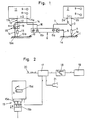
- Fig. 1 shows the electrical equalizer connection between the bodies of two objects, for example the body 1 of a storage tank and the body 10 of a tank truck.
- the equalizer connection consists in this case of an electrical busbar 6 permanently mounted on the storage tank and connected to the tank body 1 via a storage wire 5 at a storage tank terminal 1 a.
- the other end of the busbar is connected via a truck wire 14, later called distribution tank wire, to the truck 10 at a terminal 1 Oa, later called distribution tank terminal.
- a plug connector 15 is provided on the distribution tank wire 14 for connecting and disconnecting the electrical equalizer connection to/from the truck 10.
- a control circuit is provided at each end of the electrical equalizer connection, one control circuit comprising a low voltage source U 1 , a resistor 4 and an indicator means 8, 9, and the other control circuit comprising a low voltage souce U 2 , a resistor 13 and an indicator means 8, 9.
- the storage tank terminal 1 a for the equalizer connection at the storage tank 1 is connected to the control circuit via separate terminals, namely a storage tank control terminal 1 b on the storage tank 1 and an equalizer connectioon control terminal 6a on the busbar 6.
- the distribution tank terminal 10a for the equalizer connection is similarly connected to the other control circuit via separate terminals, namely a distribution tank control terminal 1 Ob on the truck 10 and an equalizer connection control terminal 6b on the busbar 6.
- the terminals 1 a and 10a are thus continuously monitored, because a current flows through each of the control circuits to indicate whether said terminals 1 a and 10a are in fact connecting the electrical equalizer connection 5, 6, 14to the bodies 1 and 10 of the storage tank truck, respectively.
- Each of the two control circuits also comprises a means for measuring the current flow 1 1 and 1 2 respectively, and a comparator which compares the measured value with predetermined values, namely a maximum and a minimum value. On the basis of these comparisons, the comparator transmits a signal to a warning means, for example a lamp 8 or 9, when the current is less than the minimum value or exceeds the maximum value.
- a warning means for example a lamp 8 or 9
- This signal can also be utilized for disconnecting the storage tank's fluid pump, thus preventing loating. If the current flow is too low, said signal will warn that at least one of the terminals has too much resistance (i.e. the terminal 1 a or 10a has too much resistance relative to the body 1 or 10), which means that the electrical equalizer connection between the storage tank and the tank truck is too poor.
- the measured corrent value is too high, this may be due to a short-circuiting of the resistor 4 or 13 in one or the other control circuit, each resistor being respectively connected between a voltage source U 1 ; U 2 and a body 1; 10.
- a short-circuiting of the resitor 4 or 13 may result from a conscious action to obtain sufficient current in the control circuit if it shows too high resistence, in orderto start the pump. This, however, will result in an excessive current value, and the fluid pump will not be able to be started.
- Each control circuit and its associated electrical components with the exception of the resistors 4; 13 can be gathered into a unit 2; with two terminals 2a, 2b; 11 a, 11 b.
- the terminals 2a, 2b on unit 2 are connected respectively to the terminal 6a on the busbar 6 and via the resistor 4to the storage tank control terminal 1 b on the storage tank 1.
- the terminals 11 a, 11 b on unit 11 are similarly connected, respectively, to the terminal 6b on the busbar 6 and the resistor 13 to the distribution tank control terminal 10b on the tank truck/vessel 10.
- Said units 2 and 11, which we may call electronic units, comprise in addition to the electrical composents mentioned above in connection with each of the control circuits (such as a low voltage source, resistor and indicator means), a means for measuring the current h; 1 2 in the respective control circuits, and a comparator which compares the measured value with predetermined values such as maximum and minimum values.
- the comparator may for example be arranged for sending a signal, perhaps via a relay output, to the indicator means 8, 9, e.g. light diodes, when the measured current either is less than or exceeds the predetermined minimum or maximum values.
- this signal can also be utilized for disconnecting the fluid pump and thereby prevent loading, because the equalizer connection between the respective objects is not in the prescribed order.
- the two electronic units 2 and 11, as seen in Fig. 1, are connected via the busbar 6 and will thus provide 100% control of the electrical equalizer connection between the bodies of the storage tank 1 and tank truck 10.
- the electronics unit 2 has a low voltage source U 2 (alternating or direct current) which produces a current 1 1 which is limited by the total resistance in the control circuit 3, 4, b, 1, a, 5, 6, 6a, 7.
- the resistor 4 is adapted to and mounted in close physical proximity to the body of the storage tank 1.
- the electronics unit 11 is identical to the unit 2, and it controls that an electrical connection exists between the busbar 6 and the body of the tank truck 10.
- the plug connector 15 for the wires 14 and 12 in the latter control circuit preferably constitutes a known per se explosion-proof switch comprising a socket member 15a and a plug member 15b, wherein the switch must be in the «off» position to enable the plug 15b to be inserted into or withdrawn from the socket 1 5a.
- the switch To establish electrical connection to the wires 12, 14 connected to the plug and socket 15b, 15a, the switch must be turned to the «on» position. This also provides a mechanical safeguard against accidental separation of the two parts 1 5a, 15b.
- a plug connector 15 of the above described type having three contacts a, b, c is utilized. Contacts a and b are used in the wire connections 14 and 12.
- the auxiliary contact c in the fixed part of the plug containing the switch, i.e., the socket 15a in Fig. 2, can be connected to a relay 17 mounted on the electrical system of the tank truck/vessel, which in turn is connected to the current source 19 for the electrical system.
- the current coil of the relay 17 will be energized so that its armature is actuated.
- the relay's contacts (which are connected between the main switch and the various user circuits in the electrical system) will be opened, and the electrical system will no longer receive current, because the connection to the electrical system's battery 19 via the main switch 18 has been broken.
- One of the contacts of the relay 17 which is open in the inactive position, can optionally be connected to a warning circuit so that when the contact is closed, a warning sound or light 21 will show that the main switch 18 has not been turned off.
Landscapes
- Loading And Unloading Of Fuel Tanks Or Ships (AREA)
- Catching Or Destruction (AREA)
- Details Of Connecting Devices For Male And Female Coupling (AREA)
Applications Claiming Priority (2)
| Application Number | Priority Date | Filing Date | Title |
|---|---|---|---|
| NO834639A NO153790C (no) | 1983-12-16 | 1983-12-16 | Kontrollsystem for avledning/utligning av elektriske potensialer mellom to gjenstander, f.eks. tankanlegg og tankkjoeretoey ved omlasting av brann-/eksplosjonsfarlige fluider. |
| NO834639 | 1983-12-16 |
Publications (2)
| Publication Number | Publication Date |
|---|---|
| EP0167557A1 EP0167557A1 (en) | 1986-01-15 |
| EP0167557B1 true EP0167557B1 (en) | 1987-10-28 |
Family
ID=19887393
Family Applications (1)
| Application Number | Title | Priority Date | Filing Date |
|---|---|---|---|
| EP85900221A Expired EP0167557B1 (en) | 1983-12-16 | 1984-12-14 | Control system for diverting/equalizing electrical potentials between two objects |
Country Status (7)
| Country | Link |
|---|---|
| US (1) | US4691198A (da) |
| EP (1) | EP0167557B1 (da) |
| AU (1) | AU3781785A (da) |
| DE (1) | DE3466972D1 (da) |
| DK (1) | DK157229C (da) |
| NO (1) | NO153790C (da) |
| WO (1) | WO1985002601A1 (da) |
Families Citing this family (14)
| Publication number | Priority date | Publication date | Assignee | Title |
|---|---|---|---|---|
| US4901195A (en) * | 1988-06-30 | 1990-02-13 | Scully Signal Company | Self-proving vehicle grounding system |
| US5034726A (en) * | 1990-03-06 | 1991-07-23 | Valvoline Oil & Chemicals Limited | Portable ground fault detector |
| US5159523A (en) * | 1990-10-24 | 1992-10-27 | Cornerstone Fuels, Inc. | Grounding system and detection circuit for fueling |
| DE4116066A1 (de) * | 1991-05-16 | 1992-11-19 | Siemens Ag | Verfahren und vorrichtung fuer einen funkenlosen potentialausgleich zwischen zwei koerpern |
| WO1998045636A1 (en) * | 1997-04-08 | 1998-10-15 | Aplc, Inc. | Truck grounding system |
| AU2352799A (en) * | 1999-02-15 | 2000-08-29 | Mico Gacanovic | Device for static electricity elimination used during racking, transportation and loading/unloading of inflammable or explosive materials |
| US6459279B2 (en) * | 1999-03-02 | 2002-10-01 | Lockheed Martin Corporation | Diagnostic testing equipment for determining properties of materials and structures of low observable vehicles |
| US6401767B1 (en) * | 2001-05-22 | 2002-06-11 | Air Products And Chemicals, Inc. | Apparatus and method for grounding compressed fuel fueling operator |
| GB2390692A (en) * | 2002-07-12 | 2004-01-14 | Ali Hassan Redha | Faulty earth bonding system detector |
| CN102180752B (zh) * | 2011-03-29 | 2012-08-22 | 大连海事大学 | 现场混装炸药车控制系统 |
| JP5884094B2 (ja) | 2011-06-24 | 2016-03-15 | パナソニックIpマネジメント株式会社 | 窒化物半導体装置 |
| CN103597588B (zh) | 2011-07-12 | 2016-10-05 | 松下知识产权经营株式会社 | 氮化物半导体装置 |
| JP5555739B2 (ja) * | 2012-04-11 | 2014-07-23 | 富士重工業株式会社 | 車両のバッテリ装置 |
| JP6844955B2 (ja) * | 2016-05-10 | 2021-03-17 | 川崎重工業株式会社 | 乗物用のヘッドランプ装置 |
Family Cites Families (8)
| Publication number | Priority date | Publication date | Assignee | Title |
|---|---|---|---|---|
| US1524423A (en) * | 1922-06-03 | 1925-01-27 | William H Chapman | Device for discharging electricity from gasoline tanks and the like |
| US1564855A (en) * | 1923-01-15 | 1925-12-08 | Associated Oil Company | Apparatus for grounding containers in the distribution of petroleum products |
| DE1099074B (de) * | 1956-12-07 | 1961-02-09 | Gilbert & Barker Mfg Co | Einrichtung zur UEberwachung der Erdungsvorrichtung eines Brennstofftanks |
| US3290668A (en) * | 1963-08-02 | 1966-12-06 | Crouse Hinds Co | Grounding and indicating device |
| US4083041A (en) * | 1974-12-16 | 1978-04-04 | Interroyal Corporation | Ground circuit monitor |
| FR2398312A1 (fr) * | 1977-07-20 | 1979-02-16 | Pipeline Service Sa | Procede de mise a la terre des navires pendant les operations de transfert de charges |
| US4220951A (en) * | 1978-09-28 | 1980-09-02 | Cathodic Protection Services, Inc. | Method and system for protecting barge |
| DE3210932C2 (de) * | 1982-03-25 | 1987-01-08 | Wintershall Ag, 3100 Celle | Vorrichtung zur Überwachung der Erdung fahrbarer Tankeinrichtungen während der Befüllung |
-
1983
- 1983-12-16 NO NO834639A patent/NO153790C/no unknown
-
1984
- 1984-12-14 AU AU37817/85A patent/AU3781785A/en not_active Abandoned
- 1984-12-14 US US06/762,150 patent/US4691198A/en not_active Expired - Fee Related
- 1984-12-14 WO PCT/NO1984/000059 patent/WO1985002601A1/en not_active Ceased
- 1984-12-14 DE DE8585900221T patent/DE3466972D1/de not_active Expired
- 1984-12-14 EP EP85900221A patent/EP0167557B1/en not_active Expired
-
1985
- 1985-08-12 DK DK364885A patent/DK157229C/da not_active IP Right Cessation
Also Published As
| Publication number | Publication date |
|---|---|
| DK157229B (da) | 1989-11-20 |
| DK364885D0 (da) | 1985-08-12 |
| NO834639L (no) | 1985-06-17 |
| US4691198A (en) | 1987-09-01 |
| DK157229C (da) | 1990-04-23 |
| AU3781785A (en) | 1985-06-26 |
| DE3466972D1 (en) | 1987-12-03 |
| EP0167557A1 (en) | 1986-01-15 |
| NO153790B (no) | 1986-02-10 |
| NO153790C (no) | 1986-05-28 |
| WO1985002601A1 (en) | 1985-06-20 |
| DK364885A (da) | 1985-08-12 |
Similar Documents
| Publication | Publication Date | Title |
|---|---|---|
| EP0167557B1 (en) | Control system for diverting/equalizing electrical potentials between two objects | |
| US4272142A (en) | Jumper cable | |
| US4871957A (en) | Method and apparatus for the automatic connection of battery cables | |
| US4463402A (en) | Safety jumper cable apparatus | |
| US4884050A (en) | Blade terminal tap fuse | |
| US3967133A (en) | Power supply means | |
| US6211577B1 (en) | Jump start circuit for a vehicle battery | |
| US4901195A (en) | Self-proving vehicle grounding system | |
| US3644745A (en) | Electrical lock for ignition systems | |
| US20040192092A1 (en) | System and method for preventing electric arcs in connectors feeding power loads and connector used | |
| US5629680A (en) | Vehicle current drain tester with memory saver | |
| US4726786A (en) | Direct current battery connector | |
| GB2327764A (en) | Measuring system with exchangeable sensors | |
| EP0824417B1 (en) | Battery clamp and vehicle comprising such battery clamp | |
| JP2010288325A (ja) | コンデンサ収容装置 | |
| US4757250A (en) | Three-conductor booster cable assembly | |
| US3957333A (en) | Universal control system interface | |
| US2876429A (en) | Theft-proof circuit for automotive vehicles | |
| US5094635A (en) | Universal automotive electrical apparatus kit connectable to automobile battery | |
| US10439413B1 (en) | Isolation jumper cables | |
| CN120056733A (zh) | 检测装置、车辆、电池管理器及回路控制方法、系统 | |
| EP0396426B1 (en) | An earthing system | |
| US3973641A (en) | Anti-theft device for motor vehicles | |
| JPH02101933A (ja) | エンジン始動補助バッテリー保護方法及び保護装置 | |
| JPH11329190A (ja) | 車両の異常報知装置 |
Legal Events
| Date | Code | Title | Description |
|---|---|---|---|
| PUAI | Public reference made under article 153(3) epc to a published international application that has entered the european phase |
Free format text: ORIGINAL CODE: 0009012 |
|
| AK | Designated contracting states |
Designated state(s): DE GB NL SE |
|
| 17P | Request for examination filed |
Effective date: 19851129 |
|
| 17Q | First examination report despatched |
Effective date: 19860821 |
|
| GRAA | (expected) grant |
Free format text: ORIGINAL CODE: 0009210 |
|
| AK | Designated contracting states |
Kind code of ref document: B1 Designated state(s): DE GB NL SE |
|
| REF | Corresponds to: |
Ref document number: 3466972 Country of ref document: DE Date of ref document: 19871203 |
|
| PLBE | No opposition filed within time limit |
Free format text: ORIGINAL CODE: 0009261 |
|
| STAA | Information on the status of an ep patent application or granted ep patent |
Free format text: STATUS: NO OPPOSITION FILED WITHIN TIME LIMIT |
|
| 26N | No opposition filed | ||
| PGFP | Annual fee paid to national office [announced via postgrant information from national office to epo] |
Ref country code: SE Payment date: 19931019 Year of fee payment: 10 |
|
| PGFP | Annual fee paid to national office [announced via postgrant information from national office to epo] |
Ref country code: DE Payment date: 19931127 Year of fee payment: 10 |
|
| PGFP | Annual fee paid to national office [announced via postgrant information from national office to epo] |
Ref country code: GB Payment date: 19931206 Year of fee payment: 10 |
|
| PGFP | Annual fee paid to national office [announced via postgrant information from national office to epo] |
Ref country code: NL Payment date: 19931231 Year of fee payment: 10 |
|
| PG25 | Lapsed in a contracting state [announced via postgrant information from national office to epo] |
Ref country code: GB Effective date: 19941214 |
|
| PG25 | Lapsed in a contracting state [announced via postgrant information from national office to epo] |
Ref country code: SE Effective date: 19941215 |
|
| EAL | Se: european patent in force in sweden |
Ref document number: 85900221.4 |
|
| PG25 | Lapsed in a contracting state [announced via postgrant information from national office to epo] |
Ref country code: NL Effective date: 19950701 |
|
| GBPC | Gb: european patent ceased through non-payment of renewal fee |
Effective date: 19941214 |
|
| NLV4 | Nl: lapsed or anulled due to non-payment of the annual fee |
Effective date: 19950701 |
|
| PG25 | Lapsed in a contracting state [announced via postgrant information from national office to epo] |
Ref country code: DE Effective date: 19950901 |
|
| EUG | Se: european patent has lapsed |
Ref document number: 85900221.4 |