EP0167331A2 - Gerät für Signalübertragung - Google Patents
Gerät für Signalübertragung Download PDFInfo
- Publication number
- EP0167331A2 EP0167331A2 EP85304453A EP85304453A EP0167331A2 EP 0167331 A2 EP0167331 A2 EP 0167331A2 EP 85304453 A EP85304453 A EP 85304453A EP 85304453 A EP85304453 A EP 85304453A EP 0167331 A2 EP0167331 A2 EP 0167331A2
- Authority
- EP
- European Patent Office
- Prior art keywords
- transmission channel
- control signal
- transmitter
- transmitting
- predetermined
- Prior art date
- Legal status (The legal status is an assumption and is not a legal conclusion. Google has not performed a legal analysis and makes no representation as to the accuracy of the status listed.)
- Granted
Links
Images


Classifications
-
- H—ELECTRICITY
- H04—ELECTRIC COMMUNICATION TECHNIQUE
- H04J—MULTIPLEX COMMUNICATION
- H04J1/00—Frequency-division multiplex systems
- H04J1/02—Details
- H04J1/08—Arrangements for combining channels
-
- H—ELECTRICITY
- H04—ELECTRIC COMMUNICATION TECHNIQUE
- H04W—WIRELESS COMMUNICATION NETWORKS
- H04W16/00—Network planning, e.g. coverage or traffic planning tools; Network deployment, e.g. resource partitioning or cells structures
- H04W16/02—Resource partitioning among network components, e.g. reuse partitioning
- H04W16/10—Dynamic resource partitioning
-
- H—ELECTRICITY
- H04—ELECTRIC COMMUNICATION TECHNIQUE
- H04M—TELEPHONIC COMMUNICATION
- H04M1/00—Substation equipment, e.g. for use by subscribers
- H04M1/72—Mobile telephones; Cordless telephones, i.e. devices for establishing wireless links to base stations without route selection
- H04M1/725—Cordless telephones
- H04M1/727—Identification code transfer arrangements
-
- H—ELECTRICITY
- H04—ELECTRIC COMMUNICATION TECHNIQUE
- H04W—WIRELESS COMMUNICATION NETWORKS
- H04W16/00—Network planning, e.g. coverage or traffic planning tools; Network deployment, e.g. resource partitioning or cells structures
- H04W16/14—Spectrum sharing arrangements between different networks
- H04W16/16—Spectrum sharing arrangements between different networks for PBS [Private Base Station] arrangements
Definitions
- This invention relates to signal transmission apparatus, and more particularly is directed to signal transmission apparatus for establishing a selected transmission channel within a multiple channel system for use in, for example, a cordless telephone.
- the radio frequency range of the electromagnetic spectrum is used for transmitting information signals between transmitters and receivers in many different types of communication systems, and is divided into standard frequency ranges which are assigned to the different types of systems to prevent interference between transmissions.
- each transmitter should have its own assigned frequency range, but while the total available radio frequency range is intrinsically limited, the number of systems is not. Instead, the assigned frequency range must somehow be shared by all the transmitters of the system. Frequently the assigned frequency range is itself divided up into a number of transmission channels, but even so there are usually more transmitters than transmission channels, so that the transmission channels themselves must be shared.
- a variety of communications systems are presently available which include a plurality of transmitters and a plurality of receivers, each transmitter being able to transmit information signals over any one of several transmission channels, and each receiver being able to receive such information signals transmitted over any ofthese transmission channels. It is usually intended that each transmitter will establish a transmission channel only with one respective receiver.
- An example of such a communication system is a cordless telephone system, where, in the USA, for example, a particular frequency range has been assigned by the Federal Communications Commission to all cordless telephones within the system. However, the number of cordless telephones already greatly exceeds the number of available transmission channels.
- each transmission channel generally includes an audio signal transmission band over which the audio signals will be transmitted once the transmission channel has been established between a particular transmitter and a particular receiver.
- the electric field intensity within the corresponding frequency range will be less than a predetermined level.
- each transmitter sequentially scans the transmission channels and detects the received electric field intensity at the corresponding frequency ranges to determine whether any of the transmission channels are unoccupied, and selects an unoccupied one for transmission.
- the audio signal transmission band thereof is used for transmitting an identifying code, uniquely identifying the transmitter to its respective receiver.
- This identifying code is used by the receiver to establish the transmission channel between itself and the transmitter.
- Each transmitter/receiver pair has identifying codes uniquely assigned to it by which each component may identify signals transmitted by the other.
- the receiver carries out a conventional polling operation whereby it checks each of the transmission channels to see if the correct identifying code is present. When this is detected, the receiver stops the polling operation and establishes the transmission channel over which it receives the correct identifying code between itself and the transmitter. Thereafter, the receiver is arranged to receive the audio signals from the transmitter over this particular transmission channel.
- the audio signal transmission band of the particular transmission channel may be used to transmit the identifying code before the transmission channel is established between the transmitter and receiver, it can no longer be so used once the transmission channel is established and an actual audio signal is being transmitted. In such case, there would be interference between the identifying code and the actual audio signal. On the other hand, if the identifying code is no longer transmitted, there is no way to continue to check that the signal is still being received from the correct transmitter. It would be highly advantageous to continue to transmit the identifying code after the transmission channel has been established.
- Another proposal is to transmit the identifying code over a separate frequency band, that is frequency division multiplexing.
- this separate frequency band has a bandwidth equivalent to the standard audio signal transmission band, this will rapidly use up the available bandwidth, reducing the number of available transmission channels.
- the bit transmission rate for the identifying code is reduced, so that it takes a relatively long time to transmit the identifying signal and thereby to establish the transmission channel between the transmitter and the receiver.
- a communications system having a plurality of transmitters for transmitting information signals including audio signals over any one of a plurality of transmission channels, and further having a plurality of receivers for receiving said information signals transmitted over any of said transmission channels, each of said transmission channels having a respective total frequency range including an allocated range for transmitting said audio signals;
- a communications system having a plurality of transmitters for transmitting information signals including audio signals over any one of a plurality of transmission channels, and further having a plurality of receivers for receiving said information signals transmitted over any of said transmission channels, each of said transmission channels having a respective total frequency range including an allocated range for transmitting said audio signals;
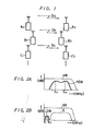
- a communications system of the type advantageously utilizing an embodiment of signal transmission apparatus has a plurality of transmitters A 1 , B 1 , C l and a plurality of receivers A 2 , B 2 , C 2 .
- the transmitter A 1 is intended to communicate only with the receiver A 2 , the transmitter B 1 with the receiver B 2' and the transmitter C l with the receiver C 2 , respectively.
- all the transmitter/receiver pairs share a single frequency range over which signals may be transmitted, and this frequency range is divided into a plurality of transmission channels, f 1 , f 2 , ... fn. It is contemplated that the total number of transmitter/receiver pairs exceeds the number of available transmission channels, so that they must share the transmission channels. Only one transmitter/receiver pair is to use any particular transmission channel at a time.
- Each transmitter/receiver pair has associated therewith a unique identifying code, provided as a string of binary digits.
- the transmitter/receiver pair A 1 , A 2 has an identifying code D a
- the transmitter/receiver pair B 1 , B 2 has an identifying code D b
- the transmitter/receiver pair C 1 , C 2 has an identifying code D c .
- the identifying codes D a , D b and D c are used by the respective transmitter/receiver pairs to ensure that, for example, the receiver A will receive signals only from the transmitter A l , as will be described below.
- each of the transmitters A l , B 1 and C 1 is capable of transmitting signals over any one of the transmission channels at a time.
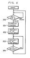
- the transmitter A 1 begins this process by sequentially scanning the available transmission channels beginning from a predetermined transmission channel to determine whether any is unoccupied, that is not being used by any of the remaining transmitters in the communications system. This is done by detecting the intensity of the electrical field in the frequency range corresponding to each transmission channel. If the transmission channel is not being used, the electric field intensity will be less than a predetermined level.
- the electric field intensity could be high due to the fact that one of the other transmitters, for example, the transmitter B 1 , is transmitting over this transmission channel, or due to some external signal totally unrelated to the particular communication system. In any event, if the electric field intensity is above the predetermined level, this of itself would create significant interference with any signals broadcast over the transmission channel at these frequencies, and so the transmission channel is not selected.
- this transmission channel for example, f, is selected.
- the transmitter A 1 uses the audio signal transmission band VB ( Figure 2A), allocated for the transmission of the audio signals and ranging from 0 to 4 KHz, to transmit the identifying code D a as a control signal.
- This control signal may advantageously be generated by minimum shift key (MSK) modulation of the binary identifying code, as illustrated in Figure 2A.
- MSK minimum shift key
- the frequencies f H1 and f H2 for the MSK modulation are chosen to be 1200 Hz and 1800 Hz, respectively, as illustrated, the resultant wide band MSK signal HDB occupies frequencies from 600 to 2400 Hz, that is, substantially the entire audio signal transmission band VB.
- the identifying code D a can be transmitted at a fast bit transmission rate of up to 1200 bits per second (bps).
- the entire identifying code D can be transmitted over the transmission channel f 1 in a very short time.
- the receiver A 2 is sequentially searching the available transmission channels in the conventional polling operation, looking for a transmission channel in which the proper identifying code is present. If the transmitter A 1 were not transmitting at all, the identifying code D a would not be found in any of the transmission channels, and so no transmission channel would be established. In the present case, it is assumed that the transmitter A 1 has selected the transmission channel f 1 and the identifying code D a appears therein. The receiver A 2 is responsive to the receipt of this correct identifying code D a to stop its searching operation and to establish the transmission channel f l , using the frequencies thereof as its operating frequencies.
- the identifying code D a is repeatedly transmitted by the transmitter A 1 .
- the transmitter A 1 stops transmitting the identifying code D over the wide band HDB.
- the elapsed time may simply be measured, or, as in the preferred embodiment described below, the receiver A 2 may retransmit a second control signal to indicate that the transmission channel f 1 has been established. In either case, the transmitter A 1 then transmits the identifying code Da by using only a narrow band signal LDB, as illustrated in Figure 2B.
- the narrow band signal LDB extends from 60 to 240 Hz within the audio signal transmission band VB, but is separate from a transmission band S used by the transmitter A 1 for transmitting the actual audio signal once the transmission channel f 1 has been established.
- the narrow band signal LDB is generated by MSK modulation of the identifying code D a using f L1 at 12 0 Hz and f L2 at 180 Hz, the bit transmission rate is 120 bps.
- the audio signal lies in the transmission band S from approximately 300 to 3400 Hz.
- bit transmission rate for the identifying code D is initially high so that the transmission channel f, can be quickly established
- bit transmission rate is relatively low after the transmission channel f has been established. Since the identifying code Dais now used only to confirm that the transmitter A is transmitting the audio signal received at the receiver A 2 , the low bit transmission rate is sufficient.
- a base unit 10 of one cordless telephone in the system includes a receiver 11 connected to an antenna lla for receiving signals transmitted over the transmission channels.
- a transmitter 12 is connected to an antenna 12a.
- the base unit 10 also includes a synthesizing oscillator 13, which operates as a local oscillator supplying local oscillation signals to the receiver 11 and the transmitter 12 for determining the receiving frequency and the transmitting frequency thereof, respectively.
- the base unit 10 includes a control section 14, which may advantageously be embodied in a suitably programmed microcomputer or microprocessor.
- a suitable microprocessor is the MSM6404, supplied by Oki Electric Industry Company Limited of Japan.
- the control section 14 also supplies a control signal to the modulator 16 to change the modulating frequencies creating the MSK modulated signal from f H1 , f H2 to f Ll' f L2' so that the MSK modulated signal no longer occupies substantially the entire audio signal transmission band VB, as illustrated in Figure 2A, but rather occupies the significantly narrower transmission band of signal LDB, illustrated in Figure 2B.
- the actual audio signal that is the telephone message signal, on the other hand, occupies the wide band transmission band S of Figure 2B.
- the MSK modulated signal LDB from the modulator 16 and the telephone message signal from the hybrid circuit H are combined in the adding circuit 17 and are then supplied to the transmitter 12 for transmission to the handset unit 20.
- the frequency band of the signal LDB used for transmitting the identifying code may be used to transmit other information. For example, if a first telephone call has been received and the base unit 10 and the handset unit 20 are in communication, and then a second incoming call appears on the telephone network line L, it is possible to send an indication thereof over this band to the handset 20 to create a "call waiting" signal. A second additional use of this band would be to transmit the above-mentioned call end signal.
- the narrow band signal LDB was generated by MSK modulation. It will be understood that other types of modulation are frequency shift keying (FSK) and phase shift keying (PSK), of which minimum shift keying is a variation. Other modulations systems may be utilized, so long as they provide a wide band modulated signal for fast bit transmission before the transmission channel is established, and a narrow band modulated signal for bit transmission at a low rate afterwards.
- FSK frequency shift keying
- PSK phase shift keying
- Other modulations systems may be utilized, so long as they provide a wide band modulated signal for fast bit transmission before the transmission channel is established, and a narrow band modulated signal for bit transmission at a low rate afterwards.
- the narrow band signal LDB in which the identifying code is transmitted after the transmission channel has been established need not be located at the low frequency end of the audio signal transmission band, but may alternatively be provided at the high frequency end.
- the communications system might be designed so that one transmitter could communicate with a specified plurality of receivers.
- one base unit could have two or more handset units associated therewith.
- the signal transmission apparatus according to the present invention could readily be adapted to establish a transmission channel only between these component.
Landscapes
- Engineering & Computer Science (AREA)
- Computer Networks & Wireless Communication (AREA)
- Signal Processing (AREA)
- Mobile Radio Communication Systems (AREA)
- Transceivers (AREA)
Applications Claiming Priority (2)
| Application Number | Priority Date | Filing Date | Title |
|---|---|---|---|
| JP59129388A JPS619039A (ja) | 1984-06-25 | 1984-06-25 | マルチチヤンネルアクセス無線方式 |
| JP129388/84 | 1984-06-25 |
Publications (3)
| Publication Number | Publication Date |
|---|---|
| EP0167331A2 true EP0167331A2 (de) | 1986-01-08 |
| EP0167331A3 EP0167331A3 (en) | 1988-08-03 |
| EP0167331B1 EP0167331B1 (de) | 1993-01-27 |
Family
ID=15008341
Family Applications (1)
| Application Number | Title | Priority Date | Filing Date |
|---|---|---|---|
| EP85304453A Expired - Lifetime EP0167331B1 (de) | 1984-06-25 | 1985-06-21 | Gerät für Signalübertragung |
Country Status (7)
| Country | Link |
|---|---|
| US (1) | US4679225A (de) |
| EP (1) | EP0167331B1 (de) |
| JP (1) | JPS619039A (de) |
| KR (1) | KR860000759A (de) |
| AU (1) | AU585514B2 (de) |
| CA (1) | CA1235753A (de) |
| DE (1) | DE3587027T2 (de) |
Cited By (7)
| Publication number | Priority date | Publication date | Assignee | Title |
|---|---|---|---|---|
| EP0304998A3 (en) * | 1987-08-26 | 1989-07-26 | N.V. Philips' Gloeilampenfabrieken | Pabx cordless telephone system |
| EP0260991A3 (de) * | 1986-09-18 | 1990-01-17 | Sony Corporation | System und Verfahren für Funkverbindung |
| US5123043A (en) * | 1986-09-18 | 1992-06-16 | Sony Corporation | Radio communication method and system |
| US5570467A (en) * | 1993-11-01 | 1996-10-29 | Telefonaktiebolaget Lm Ericsson | Method and apparatus for locating a digital control channel in a radiocommunication system |
| US5722078A (en) * | 1993-11-01 | 1998-02-24 | Ericsson Inc. | Method and apparatus for locating a digital control channel in a downbanded cellular radiocommunication system |
| WO1998058508A1 (en) * | 1997-06-16 | 1998-12-23 | Racal Communications Systems Limited | Radio communications systems |
| WO1998027768A3 (en) * | 1996-12-14 | 1998-12-23 | Central Research Lab Ltd | Mobile telephone security |
Families Citing this family (37)
| Publication number | Priority date | Publication date | Assignee | Title |
|---|---|---|---|---|
| US4741019A (en) * | 1984-03-15 | 1988-04-26 | Sanyo Electric Co., Ltd. | Cordless telephone |
| US4802200A (en) * | 1985-08-27 | 1989-01-31 | Nippon Telegraph And Telephone Corporation | Radio telephone system control apparatus and method |
| US4716407A (en) * | 1985-10-07 | 1987-12-29 | Motorola, Inc. | Trunked communication system true priority channel scan |
| US6433668B1 (en) * | 1990-05-25 | 2002-08-13 | Seiko Instruments Inc. | Paging system with spacial, frequency and time diversity |
| JPH0824388B2 (ja) * | 1987-01-16 | 1996-03-06 | 日本電信電話株式会社 | コ−ドレス電話装置の接続制御方式 |
| JPH0683674B2 (ja) * | 1987-03-17 | 1994-10-26 | 味の素株式会社 | セロビオ−スの製造法 |
| JPH0650839B2 (ja) * | 1987-06-30 | 1994-06-29 | 日本電気株式会社 | 無線電話装置 |
| JP2615635B2 (ja) * | 1987-07-16 | 1997-06-04 | 日本電気株式会社 | コードレス電話装置の接続方法 |
| US4878238A (en) * | 1987-12-23 | 1989-10-31 | Rash Mark S | Cordless telephone network |
| US5020130A (en) * | 1988-03-02 | 1991-05-28 | Motorola, Inc. | Universal frequency assignment protocol for trunked radio systems |
| JP2676766B2 (ja) * | 1988-03-04 | 1997-11-17 | 松下電器産業株式会社 | 無線通信機 |
| JPH0618343B2 (ja) * | 1988-06-21 | 1994-03-09 | 富士通株式会社 | Mca無線データ通信方法および装置 |
| JP2692863B2 (ja) * | 1988-06-24 | 1997-12-17 | 株式会社東芝 | 無線電話装置 |
| US4916728A (en) * | 1988-07-25 | 1990-04-10 | Gte Mobilnet Incorporated | Cellular telephone unit with prioritized frequency acquisition |
| US4914649A (en) * | 1988-09-12 | 1990-04-03 | Motorola, Inc. | Multiple frequency message system |
| US4953198A (en) * | 1989-07-05 | 1990-08-28 | At&T Company | Public cordless telephone |
| DE4005272A1 (de) * | 1990-02-20 | 1991-08-22 | Bosch Gmbh Robert | Verfahren zur zf-bandbreitenumschaltung sowie zf-bandbreitenumschaltvorrichtung |
| US5206855A (en) * | 1990-04-06 | 1993-04-27 | Motorola, Inc. | Multiple frequency message system |
| US5119397A (en) * | 1990-04-26 | 1992-06-02 | Telefonaktiebolaget L M Ericsson | Combined analog and digital cellular telephone system having a secondary set of control channels |
| US5388149A (en) * | 1991-06-03 | 1995-02-07 | At&T Corp. | Method and apparatus for determining availability of a public base unit for communicating with a cordless telephone in a public cordless telephone system |
| US5260988A (en) * | 1992-02-06 | 1993-11-09 | Motorola, Inc. | Apparatus and method for alternative radiotelephone system selection |
| CA2116255C (en) * | 1993-05-27 | 2000-03-07 | Richard Thomas Flanagan | Predistortion technique for communications systems |
| JPH0795285A (ja) * | 1993-09-24 | 1995-04-07 | Uniden Corp | コードレス電話装置 |
| US5625885A (en) * | 1993-12-15 | 1997-04-29 | Fujitsu Limited | Mobile communication system having pagers for providing two-way data communication between a base station and mobile stations |
| JP3456037B2 (ja) * | 1994-12-13 | 2003-10-14 | ソニー株式会社 | デジタルコードレス電話用親機 |
| FI98025C (fi) * | 1995-05-05 | 1997-03-25 | Nokia Mobile Phones Ltd | Langaton paikallisverkkojärjestelmä ja sellaisen vastaanotin |
| DE19545893C2 (de) * | 1995-12-08 | 2003-09-25 | Rohde & Schwarz | System zum automatischen Aufbau einer Funkverbindung zur Datenübertragung zwischen zwei oder mehreren Sender-Empfänger-Stationen |
| US5754944A (en) * | 1996-06-12 | 1998-05-19 | Harris Corporation | Silent link establishment |
| US5960400A (en) * | 1996-12-30 | 1999-09-28 | Paradyne Corporation | Signal transfer acceleration system and method for accelerating transfer of an audio signal through a communications channel |
| US6212396B1 (en) | 1997-03-27 | 2001-04-03 | Nortel Networks Limited | Generic handset programming and configuration |
| US6249213B1 (en) * | 1998-12-17 | 2001-06-19 | Intel Corporation | Method for transmitting information over an alternating current power line through a plurality of frequency orthogonal subchannels |
| KR100367434B1 (ko) * | 1999-02-10 | 2003-01-10 | 주식회사 만도 | 전동식 파워 스티어링 장치 |
| DE10036100C1 (de) * | 2000-07-25 | 2002-02-14 | Adidas Int Bv | Schuh |
| US7236757B2 (en) * | 2001-07-11 | 2007-06-26 | Vativ Technologies, Inc. | High-speed multi-channel communications transceiver with inter-channel interference filter |
| US7295623B2 (en) * | 2001-07-11 | 2007-11-13 | Vativ Technologies, Inc. | High-speed communications transceiver |
| US20030112896A1 (en) * | 2001-07-11 | 2003-06-19 | Raghavan Sreen A. | Multi-channel communications transceiver |
| US7388904B2 (en) * | 2003-06-03 | 2008-06-17 | Vativ Technologies, Inc. | Near-end, far-end and echo cancellers in a multi-channel transceiver system |
Family Cites Families (7)
| Publication number | Priority date | Publication date | Assignee | Title |
|---|---|---|---|---|
| US3845391A (en) * | 1969-07-08 | 1974-10-29 | Audicom Corp | Communication including submerged identification signal |
| US4053717A (en) * | 1976-02-27 | 1977-10-11 | David Eugene Snider | Cordless telephone |
| US4332981A (en) * | 1980-08-15 | 1982-06-01 | Edward Rossi Palombi | Cordless telephone |
| AT391234B (de) * | 1981-09-08 | 1990-09-10 | Center Nachrichtentechnische A | Drahtloser telefonapparat |
| US4467141A (en) * | 1981-09-08 | 1984-08-21 | Portaphone Ag | Telecommunication system with radio line |
| SE430013B (sv) * | 1981-12-21 | 1983-10-10 | Ericsson Telefon Ab L M | Forfarande och anleggning for overforing av telefonsamtal till en berbar, tradlos telefonapparat |
| US4541118A (en) * | 1983-12-22 | 1985-09-10 | Motorola, Inc. | SSB System with pilot coded squelch |
-
1984
- 1984-06-25 JP JP59129388A patent/JPS619039A/ja active Pending
-
1985
- 1985-06-18 US US06/745,943 patent/US4679225A/en not_active Expired - Fee Related
- 1985-06-18 AU AU43789/85A patent/AU585514B2/en not_active Ceased
- 1985-06-18 CA CA000484297A patent/CA1235753A/en not_active Expired
- 1985-06-21 DE DE8585304453T patent/DE3587027T2/de not_active Expired - Fee Related
- 1985-06-21 EP EP85304453A patent/EP0167331B1/de not_active Expired - Lifetime
- 1985-06-25 KR KR1019850004496A patent/KR860000759A/ko not_active Ceased
Cited By (11)
| Publication number | Priority date | Publication date | Assignee | Title |
|---|---|---|---|---|
| EP0260991A3 (de) * | 1986-09-18 | 1990-01-17 | Sony Corporation | System und Verfahren für Funkverbindung |
| US5123043A (en) * | 1986-09-18 | 1992-06-16 | Sony Corporation | Radio communication method and system |
| EP0304998A3 (en) * | 1987-08-26 | 1989-07-26 | N.V. Philips' Gloeilampenfabrieken | Pabx cordless telephone system |
| US5570467A (en) * | 1993-11-01 | 1996-10-29 | Telefonaktiebolaget Lm Ericsson | Method and apparatus for locating a digital control channel in a radiocommunication system |
| US5722078A (en) * | 1993-11-01 | 1998-02-24 | Ericsson Inc. | Method and apparatus for locating a digital control channel in a downbanded cellular radiocommunication system |
| US5970057A (en) * | 1993-11-01 | 1999-10-19 | Telefonaktiebolaget Lm Ericsson | Method and apparatus for distinguishing between a digital control channel and a digital traffic channel in a radiocommunication system |
| US6058108A (en) * | 1993-11-01 | 2000-05-02 | Telefonaktiebolaget Lm Ericsson | Method and apparatus for locating a digital control channel in a radiocommunication system |
| WO1998027768A3 (en) * | 1996-12-14 | 1998-12-23 | Central Research Lab Ltd | Mobile telephone security |
| WO1998058508A1 (en) * | 1997-06-16 | 1998-12-23 | Racal Communications Systems Limited | Radio communications systems |
| EP0886451A1 (de) * | 1997-06-16 | 1998-12-23 | Racal Communications Systems Limited | Funkkommunikationssystem |
| US6252859B1 (en) | 1997-06-16 | 2001-06-26 | Racal Communications Systems Limited | Radio communications system |
Also Published As
| Publication number | Publication date |
|---|---|
| EP0167331A3 (en) | 1988-08-03 |
| US4679225A (en) | 1987-07-07 |
| DE3587027T2 (de) | 1993-07-22 |
| CA1235753A (en) | 1988-04-26 |
| EP0167331B1 (de) | 1993-01-27 |
| AU585514B2 (en) | 1989-06-22 |
| DE3587027D1 (de) | 1993-03-11 |
| KR860000759A (ko) | 1986-01-30 |
| JPS619039A (ja) | 1986-01-16 |
| AU4378985A (en) | 1986-01-02 |
Similar Documents
| Publication | Publication Date | Title |
|---|---|---|
| EP0167331B1 (de) | Gerät für Signalübertragung | |
| EP0752192B1 (de) | Kommunikation über einen direktmoduskanal | |
| US4783844A (en) | Apparatus for transmitting and recording signals | |
| US5850593A (en) | Mobile communication for a mobile station near or outside a service area of a base station | |
| US4650928A (en) | Signal transmitting and/or receiving apparatus | |
| EP0631417B1 (de) | Verfahren und Steuereinrichtung für ein Funktelefonsystem | |
| EP1892868A1 (de) | CDMA Übertragungsverfahren, und Basisstation und Mobilstation dafür | |
| US5901342A (en) | Establishment of a call in a mobile communication system | |
| AU715234B2 (en) | Checking the presence of mobile stations communicating on a direct mode channel | |
| CA2137386C (en) | Time division multiple access mobile wireless telecommunication system | |
| JPS61260727A (ja) | 無線伝送系 | |
| NZ201827A (en) | Scanning radiophone system | |
| US6108551A (en) | Assigning of transmission turns to radio units | |
| US5210752A (en) | Radio tele-communication system using multichannel access scheme | |
| JPS60232744A (ja) | 通信方式 | |
| JP3864578B2 (ja) | 無線通信システム | |
| JPH09107344A (ja) | 音声信号/非音声信号の同時伝送方法及び装置 | |
| US4578817A (en) | Method for establishing communications in a network of frequency-jumping transmitter-receiver stations and a station for the utilization of said method | |
| KR19990082058A (ko) | 전기 통신 시스템, 채널 선택 프로토콜, 및 무선 스테이션 | |
| JPH04297137A (ja) | 移動通信における接続制御方式 | |
| EP1077568B1 (de) | Telefonport mit automatischer Detektierung und Sicherung | |
| JPH0712232B2 (ja) | コードレス電話方式 | |
| EP0519549A2 (de) | Entscheidungsverfahren für Funkkommunikationssystem und System dafür | |
| KR930002793Y1 (ko) | 송수신장치 | |
| JPS59123325A (ja) | 分散基地局自動選択制御方式 |
Legal Events
| Date | Code | Title | Description |
|---|---|---|---|
| PUAI | Public reference made under article 153(3) epc to a published international application that has entered the european phase |
Free format text: ORIGINAL CODE: 0009012 |
|
| AK | Designated contracting states |
Designated state(s): DE FR GB NL |
|
| PUAL | Search report despatched |
Free format text: ORIGINAL CODE: 0009013 |
|
| AK | Designated contracting states |
Kind code of ref document: A3 Designated state(s): DE FR GB NL |
|
| 17P | Request for examination filed |
Effective date: 19881202 |
|
| 17Q | First examination report despatched |
Effective date: 19910222 |
|
| GRAA | (expected) grant |
Free format text: ORIGINAL CODE: 0009210 |
|
| AK | Designated contracting states |
Kind code of ref document: B1 Designated state(s): DE FR GB NL |
|
| REF | Corresponds to: |
Ref document number: 3587027 Country of ref document: DE Date of ref document: 19930311 |
|
| ET | Fr: translation filed | ||
| PLBE | No opposition filed within time limit |
Free format text: ORIGINAL CODE: 0009261 |
|
| STAA | Information on the status of an ep patent application or granted ep patent |
Free format text: STATUS: NO OPPOSITION FILED WITHIN TIME LIMIT |
|
| 26N | No opposition filed | ||
| PGFP | Annual fee paid to national office [announced via postgrant information from national office to epo] |
Ref country code: FR Payment date: 19950609 Year of fee payment: 11 |
|
| PGFP | Annual fee paid to national office [announced via postgrant information from national office to epo] |
Ref country code: GB Payment date: 19950612 Year of fee payment: 11 |
|
| PGFP | Annual fee paid to national office [announced via postgrant information from national office to epo] |
Ref country code: DE Payment date: 19950617 Year of fee payment: 11 |
|
| PGFP | Annual fee paid to national office [announced via postgrant information from national office to epo] |
Ref country code: NL Payment date: 19950628 Year of fee payment: 11 |
|
| PG25 | Lapsed in a contracting state [announced via postgrant information from national office to epo] |
Ref country code: GB Effective date: 19960621 |
|
| PG25 | Lapsed in a contracting state [announced via postgrant information from national office to epo] |
Ref country code: NL Effective date: 19970101 |
|
| GBPC | Gb: european patent ceased through non-payment of renewal fee |
Effective date: 19960621 |
|
| PG25 | Lapsed in a contracting state [announced via postgrant information from national office to epo] |
Ref country code: FR Effective date: 19970228 |
|
| PG25 | Lapsed in a contracting state [announced via postgrant information from national office to epo] |
Ref country code: DE Effective date: 19970301 |
|
| NLV4 | Nl: lapsed or anulled due to non-payment of the annual fee |
Effective date: 19970101 |
|
| REG | Reference to a national code |
Ref country code: FR Ref legal event code: ST |