EP0166719A2 - Structural joint - Google Patents
Structural joint Download PDFInfo
- Publication number
- EP0166719A2 EP0166719A2 EP85890142A EP85890142A EP0166719A2 EP 0166719 A2 EP0166719 A2 EP 0166719A2 EP 85890142 A EP85890142 A EP 85890142A EP 85890142 A EP85890142 A EP 85890142A EP 0166719 A2 EP0166719 A2 EP 0166719A2
- Authority
- EP
- European Patent Office
- Prior art keywords
- profile seal
- central web
- profile
- panels
- strip
- Prior art date
- Legal status (The legal status is an assumption and is not a legal conclusion. Google has not performed a legal analysis and makes no representation as to the accuracy of the status listed.)
- Withdrawn
Links
Images
Classifications
-
- E—FIXED CONSTRUCTIONS
- E01—CONSTRUCTION OF ROADS, RAILWAYS, OR BRIDGES
- E01C—CONSTRUCTION OF, OR SURFACES FOR, ROADS, SPORTS GROUNDS, OR THE LIKE; MACHINES OR AUXILIARY TOOLS FOR CONSTRUCTION OR REPAIR
- E01C11/00—Details of pavings
- E01C11/02—Arrangement or construction of joints; Methods of making joints; Packing for joints
- E01C11/04—Arrangement or construction of joints; Methods of making joints; Packing for joints for cement concrete paving
- E01C11/10—Packing of plastic or elastic materials, e.g. wood, resin
- E01C11/106—Joints with only prefabricated packing; Packings therefor
-
- E—FIXED CONSTRUCTIONS
- E01—CONSTRUCTION OF ROADS, RAILWAYS, OR BRIDGES
- E01C—CONSTRUCTION OF, OR SURFACES FOR, ROADS, SPORTS GROUNDS, OR THE LIKE; MACHINES OR AUXILIARY TOOLS FOR CONSTRUCTION OR REPAIR
- E01C11/00—Details of pavings
- E01C11/02—Arrangement or construction of joints; Methods of making joints; Packing for joints
- E01C11/04—Arrangement or construction of joints; Methods of making joints; Packing for joints for cement concrete paving
- E01C11/10—Packing of plastic or elastic materials, e.g. wood, resin
-
- E—FIXED CONSTRUCTIONS
- E01—CONSTRUCTION OF ROADS, RAILWAYS, OR BRIDGES
- E01C—CONSTRUCTION OF, OR SURFACES FOR, ROADS, SPORTS GROUNDS, OR THE LIKE; MACHINES OR AUXILIARY TOOLS FOR CONSTRUCTION OR REPAIR
- E01C11/00—Details of pavings
- E01C11/22—Gutters; Kerbs ; Surface drainage of streets, roads or like traffic areas
- E01C11/224—Surface drainage of streets
- E01C11/227—Gutters; Channels ; Roof drainage discharge ducts set in sidewalks
Definitions
- the invention relates to a profile seal, in particular for filling the joints of panels, e.g. for roadways, sidewalks, floors or the like, consisting of a central web with cross bars protruding on both sides.
- the term slab is to be understood in its wisest meaning and includes e.g. Concrete slabs, paving stones, plastic stones etc.
- the joints between the panels are cast with a sealing compound, preferably bitumen. Due to the shaking of the slabs caused by rolling traffic, in particular trams, the casting compounds are pushed out of the joints, whereupon the slabs, in particular concrete slabs, collide in the absence of a lining between them, shift and cause a noise.
- Joint tapes made of plastic for filling joints between concrete blocks of larger buildings have become known.
- the joint tapes are predominantly, depending on their position, permanently installed in the formwork, with an essentially tubular profile formed approximately in the longitudinal center of the band determining the joint width prevent into the joint.
- joint cover tapes made of plastic have become known, which are resistant to bitumen emulsion and seal the joint on the outside against the ingress of water.
- the well-known joint tapes have the task of providing safety in the 3-tone structure with water pressure and moisture. Sound, shock and heat-insulating as well as cold-insulating effect is here not aimed.
- AT-PS 313 540 discloses a seal with a profile strand made of elastically deformable material that can be pressed into an expansion joint.
- this profile strand consists of a divided central web, on which oblique transverse strips protrude upwards on both sides, which are closed off by outside walls, so that closed chambers are formed.
- a V-shaped channel is formed by the top cross bars, which can be covered by an additional profile bar. Due to the V-shaped design of the gutter, a potting compound would be poorly anchored. Since the profile strand has a complicated cross-sectional shape, its production is also complex.
- the object of the invention is to provide a profile seal with which, above all, a shock-absorbing, but at most also a heat and cold-insulating effect is achieved, the casting compound also being to be firmly and permanently anchored.
- the central web carries a U-shaped channel on the upper side, the side walls of which form a dovetail-shaped groove after laying the plates in the compressed state.
- the central web carries a U-shaped groove on the upper side, the side walls of which can be pressed in and form a dovetail-shaped groove after laying the panels in the compressed state, at least along damping material is provided for part of the profile.
- the damping mass also achieves a sound-absorbing effect and supports the shock-absorbing effect.
- the side walls preferably have protruding projections on the upper edge.
- openings are provided in the bottom of the U-shaped channel.
- the inventive measure in the gap between the plates insert a compressible profile seal with a dovetail groove at least in the use position, the advantage is achieved that the potting compound can no longer be pushed out of the joint by vibrations of the plates and also in the event of a renewal of the The gasket can be removed from the joint between the panels including the sealing compound, whereupon the panels can be replaced or repaired.
- the profile seal 1 consists of a central web 2, of which two transverse strips 3 and 3 ', which protrude laterally and laterally, are arranged on both sides.
- the center web 2 carries on its upper side a U-shaped channel 4, the side walls 5 of which initially run upward and then have extensions 6 projecting laterally. Openings 7 can be present in the bottom of the U-shaped channel 4, which serve as drainage if no potting compound is filled into the channel 4.
- the transverse strips 3 or 3 ' run obliquely upwards, but they can also protrude obliquely downwards or run horizontally, and at most have only bent the ends, so that the strips 3 or 3' are bent inwards under lateral pressure .
- the extensions 6 preferably run horizontally and the side walls 5 vertically upwards.
- the profile seal 1 is made of a material, preferably plastic, which is so elastic that the cross strips 3 and W. 3 'and the side walls 5 can be bent towards each other, so that the side walls 5 form a dovetail-shaped groove in the position of use.
- a strip 11 of a damping material e.g. Foam rubber, clamped, which in the present case extends along the entire length of the central web 2.
- This strip can also be provided only in sections. It can also be arranged additionally between the transverse strips 3 and 3 'or only between them, or, as shown in FIG. 2, when a double-walled central web 2 is formed between the two walls 2', 2 "of the central web 2. However, there is also the possibility to arrange it below the strips 3 'or the central web 2. The number of the transverse strips 3 or 3' projecting laterally is left to the designer.
- the strips 11 can be inserted or poured or injected, but there is also the possibility to produce the entire profile with the strip 11 in casting or injection molding material, which is designed so that the profile walls stiffen and cross bars pressed inward around the root 3 or 3 'and side walls 5 form.
- the strips 11 can end with the bar 3, but they can also protrude beyond the bar 3, as shown in FIG. 1, and only in the compressed state into the space between the bars 3 and the floor 10 or between the bars 3 , 3 'are pressed in.
- Fig. 3 shows the profile seal 1 in the installed state between two plates 8.
- the side walls 5 are pressed against one another due to the projections 6 resting on the plates 8 and thereby form a dovetail-shaped groove 4 'by which the casting compound is anchored.
- the joint between the plates can also be cast on the bottom.
- the profile seal 1 can be pressed into the joint with a press ram so that the lowermost cross bars 3 'penetrate into the sealing compound 9 and at their ends deform inwards, so that the sealing compound in the space between the cross bars 3, 3 'and penetrates the central web 2 and thereby anchoring the sealing compound and the cross bars is brought about.
- the sealing compound connects to the plastic and, with the participation of the anchoring, as shown in FIG. 3, prevents it from escaping from the joint.
- Another advantage of the profile gasket according to the invention is that this profile gasket is flush with the upper carriageway or walking surface, so that the sealing compound does not come into contact with the side walls of the plates or only comes into contact to a small extent and therefore the side winds not glued, which makes it possible to remove the sealing compound with the profile seal from the joints during renovation or improvement work, after which the loosened panels can be easily lifted off the floor.
- channel 4 or groove 4 ' is not filled with potting compound, water can flow through the openings 7, which enters the space between the upper cross bar 3 and the bottom 10 of the channel 4, and can be discharged laterally if there is no streak 14 is made of cushioning material, or this strip consists of open-cell foam.
- the profile seal works like a shock absorber and muffler and can also be installed in joints in panels that have already been laid.
- the air cushion formed between the panels as a result of the profile seal also provides thermal and cold insulation.
Abstract
Description
Die Erfindung betrifft eine Profildichtung, insbesondere zum Ausfüllen der Fugen von Platten, z.B. bei Fahrbahnen, Gehsteigen, Fußböden od.dgl., bestehend aus einem Mittelsteg mit beidseitig abstehenden Querleisten. Hiebei ist der Begriff Platten in seiner weistesten Bedeutung zu verstehen und umfaßt z.B. Betonplatten, Pflastersteine, Steine aus Kunststoff etc.The invention relates to a profile seal, in particular for filling the joints of panels, e.g. for roadways, sidewalks, floors or the like, consisting of a central web with cross bars protruding on both sides. The term slab is to be understood in its wisest meaning and includes e.g. Concrete slabs, paving stones, plastic stones etc.
Bei der Verlegung von Platten, Steinen und anderen Fertigbauteilen auf Straßen, insbesondere zwischen den Schienen von Straßenbahnen, werden die Fugen zwischen den Platten mit einer Vergußmasse, vorzugsweise Bitumen, vergossen. Durch die vom rollenden Verkehr, insbesondere von Straßenbahnen, verursachten Erschütterungen der Platten werden die Vergußmassen aus den Fugen hinausgedrückt, worauf die Platten, insbesondere Betonplatten in Ermangelung eines zwischen ihnen vorhandenen Futters aneinanderstoßen, sich verschieben und ein Geräusch verursachen.When laying panels, stones and other prefabricated components on roads, especially between the rails of trams, the joints between the panels are cast with a sealing compound, preferably bitumen. Due to the shaking of the slabs caused by rolling traffic, in particular trams, the casting compounds are pushed out of the joints, whereupon the slabs, in particular concrete slabs, collide in the absence of a lining between them, shift and cause a noise.
Es sind wohl Fugenbänder aus Kunststoff zum Ausfüllen von Fugen zwischen Betonblöcken größerer Bauwerke bekannt geworden. Die Fugenbänder werden vorwiegend, je nach Lage, fest in die Schalung eingebaut, wobei ein etwa in der Längsmitte des Bandes ausgeformtes im wesentlichen schlauchförmiges Profil die Fugenbreite bestimmt.Nach Fertigstellung der Schalung werden Füllstoffplatten eingelegt, die das Fugenband abstützen und gleichzeitig das Einfließen von Beton in die Fuge verhindern. Schließlich sind Fugenabdeckbänder aus Kunststoff bekannt geworden, welche gegen Bitumenemulsion beständig sind und die Fuge außenseitig gegen Eindringen von Wasser abdichten.Joint tapes made of plastic for filling joints between concrete blocks of larger buildings have become known. The joint tapes are predominantly, depending on their position, permanently installed in the formwork, with an essentially tubular profile formed approximately in the longitudinal center of the band determining the joint width prevent into the joint. Finally, joint cover tapes made of plastic have become known, which are resistant to bitumen emulsion and seal the joint on the outside against the ingress of water.
Die bekannten Fugenbänder haben die Aufgabe Sicherheit im 3etonbauwerk bei Wasserdruck und Feuchtigkeit zu bieten. Schall-, stoß- und wärmedämmende, sowie kältedämmende Wirkung ist hiebei nicht angestrebt.The well-known joint tapes have the task of providing safety in the 3-tone structure with water pressure and moisture. Sound, shock and heat-insulating as well as cold-insulating effect is here not aimed.
Durch die AT-PS 313 540 ist eine Abdichtung mit einem in eine Dehnfuge eindrückbaren Profilstrang aus elastisch verformbarem Werkstoff bekannt. Dieser Profilstrang besteht im eingebauten Zustand aus einem geteilten Mittelsteg, an welchem beidseitig schräge Querleisten nach oben abstehen, die durch außenseitige Wände abgeschlossen sind, sodaß geschlossene Kammern entstehen. Durch die obersten Querleisten wird eine V-förmige Rinne gebildet, die durch eine zusätzliche Profilleiste abgedeckt werden kann. Wegen der V-förmigen Ausbildung der Rinne würde eine eingebrachte Vergußmasse schlecht verankert sein. Da der Profilstrang eine komplizierte Querochnittsform aufweist, ist dessen Herstellung auch aufwendig.AT-PS 313 540 discloses a seal with a profile strand made of elastically deformable material that can be pressed into an expansion joint. In the installed state, this profile strand consists of a divided central web, on which oblique transverse strips protrude upwards on both sides, which are closed off by outside walls, so that closed chambers are formed. A V-shaped channel is formed by the top cross bars, which can be covered by an additional profile bar. Due to the V-shaped design of the gutter, a potting compound would be poorly anchored. Since the profile strand has a complicated cross-sectional shape, its production is also complex.
Aufgabe der Erfindung ist die Schaffung einer Profildichtung, mit der vor allem eine stoßdämmende, allenfalls aber auch eine wärme- und kältedämmende Wirkung erzielt wird, wobei auch die Vergußmasse fest und dauerhaft verankert werden soll.The object of the invention is to provide a profile seal with which, above all, a shock-absorbing, but at most also a heat and cold-insulating effect is achieved, the casting compound also being to be firmly and permanently anchored.
Zur Lösung dieser Aufgabe wird bei einer elastischen Profildichtung der eingangs genannten Art erfindungsgemäß vorgeschlagen, daß der Mittelsteg auf der Oberseite eine U-förmige Rinne trägt, deren Seitenwände nach Verlegen der Platten im zusammengedrückten Zustand eine schwalbenschwanzförmige Nut bilden.To solve this problem, it is proposed according to the invention in the case of an elastic profile seal of the type mentioned at the outset that the central web carries a U-shaped channel on the upper side, the side walls of which form a dovetail-shaped groove after laying the plates in the compressed state.
Nach einem weiteren Merkmal der Erfindung wird bei der Profildichtung der eingangs genannten Art erfindungsgemäß vorgeschlagen, daß der Mittelsteg auf der Oberseite eine U-förmige Rinne trägt, deren Seitenwände eindrückbar sind und nach Verlegung der Platten im zusammengedrückten Zustand eine schwalbenschwanzförmige Nut bilden, wobei zumindest entlang eines Teils des Profils dämpfendes Material vorgesehen ist.According to a further feature of the invention, it is proposed according to the invention in the case of the profile seal of the type mentioned at the outset that the central web carries a U-shaped groove on the upper side, the side walls of which can be pressed in and form a dovetail-shaped groove after laying the panels in the compressed state, at least along damping material is provided for part of the profile.
Durch die dämpfende Masse wird außerdem eine schalldämmende Wirkung erzielt, und die stoßdämmende Wirkung unterstützt.The damping mass also achieves a sound-absorbing effect and supports the shock-absorbing effect.
Vorzugsweise weisen die Seitenwände am oberen Rand seitlich abstehende Fortsätze auf.The side walls preferably have protruding projections on the upper edge.
Des weiteren ist vorgesehen, daß im Boden der U-förmigen Rinne Durchbrechungen vorhanden sind.Furthermore, it is provided that openings are provided in the bottom of the U-shaped channel.
Durch die erfindungsgemäße Maßnahme in den Spalt zwischen den Platten eine zusammendrückbare Profildichtung mit einer zumindest in der Gebrauchstellung schwalbenschwanzförmigen Nut einzulegen, wird der Vorteil erzielt, daß die Vergußmasse durch Erschütterungen der Platten aus der Fuge nicht mehr hinausgedrückt werden kann und außerdem im Fall einer Erneuerung der Fahrbahn oder des Gehweges die Profildichtung aus der Fuge zwischen den Platten einschließlich der Vergußmasse entfernt werden kann, worauf die Platten ausgewechselt oder repariert werden können.The inventive measure in the gap between the plates insert a compressible profile seal with a dovetail groove at least in the use position, the advantage is achieved that the potting compound can no longer be pushed out of the joint by vibrations of the plates and also in the event of a renewal of the The gasket can be removed from the joint between the panels including the sealing compound, whereupon the panels can be replaced or repaired.
Weitere Maßnahmen und Vorteile der Erfindung werden anhand der Zeichnung näher erläutert, in welcher zwei Ausführungsbeispiele des Erfindungsgegenstandes dargestellt sind. Es zeigen
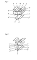
- Fig. 1 eine schaubildliche Darstellung einer erfindungsgemäßen Profildichtung vor dem Einbringen zwischen zwei Platten,
- Fig. 2 eine schaubildliche Darstellung der erfindungsgemäßen _ Profildichtung nach Fig. 1 in geänderter Ausführungsform und
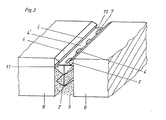
- Fig. 3 zwei verlegte Bauplatten in schaubildlicher Darstellung mit einer dazwischen verlegten Profildichtung nach Fig. 1.
- 1 is a perspective view of a profile seal according to the invention before insertion between two plates,
- 2 shows a diagrammatic representation of the profile seal according to the invention according to FIG. 1 in a modified embodiment and
- 3 shows two laid building boards in a diagrammatic representation with a profile seal according to FIG. 1 laid in between.
Die Profildichtung 1 besteht, wie die Fig. 1 und 2 zeigen, aus einem Mittelsteg 2, von dem beidseitig je zwei in Höhenabstand seitlich abstehende Querleisten 3 bzw. 3' angeordnet sind. Der Mittelsteg 2 trägt auf seiner Oberseite eine U-förmige Rinne 4, deren Seitenwände 5 zunächst nach oben verlaufen und anschließend seitlich abstehende Fortsätze 6 aufweisen. Im Boden der U-förmigen Rinne 4 können Durchbrechungen 7 vorhanden sein, die als Drainage dienen, wenn keine Vergußmasse in die Rinne 4 eingefüllt wird.As shown in FIGS. 1 and 2, the
Im vorliegenden Fall verlaufen die Querleisten 3 bzw. 3' schräg nach oben, sie können aber auch schräg nach unten abstehen oder horizontal verlaufen, und allenfalls nur die Enden abgebogen haben, sodaß die Leisten 3 bzw. 3' unter seitlichem Druck nach innen abgebogen werden. Vorzugsweise verlaufen die Fortsätze 6 horizontal und die Seitenwände 5 vertikal nach oben. Die Profildichtung 1 ist aus einem Material vorzugsweise Kunststoff hergestellt, welches bzw. welcher soweit elastisch ist, daß die Querleisten 3 bzW. 3' und die Seitenwände 5 zueinander abgebogen werden können, sodaß die Seitenwände 5 in der Gebrauchslage eine schwalbenschwanzförmige Nut bilden.In the present case, the
Bei der Ausführungsform der Profildichtung 1 nach Fig. 1 ist zwischen dem Boden 10 und der obersten Querleiste 3 ein Streifen 11 aus einem dämpfenden Material, z.B. Schaumgummi, eingeklemmt, welcher sich im vorliegenden Fall entlang der gesamten Länge des Mittelstegs 2 erstreckt. Dieser Streifen kann aber auch nur abschnittweise vorgesehen sein. Er kann auch zusätzlich zwischen den Querleisten 3 und 3' oder nur zwischen diesen, oder wie Fig. 2 zeigt, bei Ausbildung eines doppelwandigen Mittelsteges 2 zwischen den beiden Wänden 2',2" des Mittelstegs 2 angeordnet sein. Es besteht aber auch die Möglichkeit, ihn unterhalb der Leisten 3' bzw. des Mittelstegs 2 anzuordnen. Die Anzahl der seitlich abstehenden Querleisten 3 bzw. 3' ist dem Konstrukteur überlassen.In the embodiment of the
Die Streifen 11 können eingelegt oder eingegossen bzw. eingespritzt werden, es besteht aber auch die Möglichkeit, das gesamte Profil mit dem Streifen 11 in Guß- oder Spritzgußmaterial herzustellen, welches so beschaffen ist, daß die Profilwände versteifen und nach innen um die Wurzel eindrückbare Querleisten 3 bzw.3' und Seitenwände 5 bilden.The
Die Streifen 11 können mit der Leiste 3 abschließen, sie können aber auch über die Leiste 3, wie in Fig. 1 dargestellt, hinausragen, und erst im zusammengedrückten Zustand in den Raum zwischen den Leisten 3 und dem Boden 10 bzw. zwischen den Leisten 3,3' eingedrückt werden.The
Fig. 3 zeigt die Profildichtung 1 im eingebauten Zustand zwischen zwei Platten 8. Hiebei sind die Seitenwände 5 bedingt durch die an den Platten 8 anliegenden Fortsätze 6 gegeneinander zusammengedrückt und bilden dadurch eine schwalbenschwanzförmige Nut 4', durch welche die Vergußmasse verankert wird. Wie in Fig. 3 bei 9 angedeutet ist, kann die Fuge zwischen den Platten auch bodenseitig vergossen sein. In diesem Fall kann die Profildichtung 1 in die Fuge mit einem Preßstempel so weit eingedrückt werden, daß die untersten Querleisten 3' in die Vergußmasse 9 eindringen und an ihren Enden sich nach innen verformen, sodaß die Vergußmasse in den Raum zwischen den Querleisten 3,3' und dem Mittelsteg 2 eindringt und dadurch eine Verankerung der Vergußmasse und der Querleisten herbeigeführt wird.Fig. 3 shows the
Die Vergußmasse verbindet sich mit dem Kunststoff und verhindert unter Mitwirkung der Verankerung, wie sie in Fig. 3 dargestellt ist, daß sie aus der Fuge austreten kann. Ein weiterer Vorteil der erfindungsgemäßeqProfildichtung besteht darin, daß diese Profildichtung mit der oberen Fahrbahn oder Gehfläche abschließt, sodaß die Vergußmasse mit den Seitenwänden der Platten nicht oder nur im geringen Ausmaß in Berührung tritt und daher die Seitenwinde nicht verklebt, wodurch es möglich ist, bei Erneuerungs- oder Verbesserungsarbeiten die Vergußmasse mit der Profildichtung aus den Fugen herauszunehmen, worauf die gelockerten Platten leicht aus dem Boden gehoben werden können.The sealing compound connects to the plastic and, with the participation of the anchoring, as shown in FIG. 3, prevents it from escaping from the joint. Another advantage of the profile gasket according to the invention is that this profile gasket is flush with the upper carriageway or walking surface, so that the sealing compound does not come into contact with the side walls of the plates or only comes into contact to a small extent and therefore the side winds not glued, which makes it possible to remove the sealing compound with the profile seal from the joints during renovation or improvement work, after which the loosened panels can be easily lifted off the floor.
Falls die Rinne 4 bzw. Nut 4' mit Vergußmasse nicht ausgefüllt wird, kann durch die Durchbrechungen 7 Wasser abfließen, welches in den Raum zwischen der oberen Querleiste 3 und dem Boden 10 der Rinne 4 gelangt, und seitlich abgeführt werden kann, falls kein Streifen 14 aus dämpfendem Material vorhanden ist, oder dieser Streifen aus offenzelligem Schaumstoff besteht.If the
Die Profildichtung wirkt nach Art eines Stoß- und Schalldämpfers und kann auch in Fugen bereits verlegter Platten eingebracht werden.The profile seal works like a shock absorber and muffler and can also be installed in joints in panels that have already been laid.
Durch den infolge der Profildichtung gebildeten Luftpolster zwischen den Platten wird auch eine Wärme- und Kältedämmung erzielt.The air cushion formed between the panels as a result of the profile seal also provides thermal and cold insulation.
Ein weiterer Vorteil der Profildichtung ergibt sich aus der Tatsache, daß die Vergußmasse nicht mehr wie bisher die gesamte Fuge ausfüllen muß, sodaß eine Verbilligung der Bauweise erzielt wird, da die Vergußmasse in der Beschaffung wesentlich teurer als die Profildichtung ist.Another advantage of the profile seal results from the fact that the sealing compound no longer has to fill the entire joint as before, so that the construction is cheaper because the sealing compound is much more expensive to procure than the profile seal.
Selbstverständlich können im Rahmen der Erfindung verschiedenekonstruktive Abänderungen vorgenommen werden. So besteht die Möglichkeit, beim Einschäumen des Streifens 11, in den ihm benachbarten Mittelsteg 2 Durchbrechungen vorzusehen, durch welche das Schaummaterial von einer auf die andere Seite des Profils eindringen kann, wodurch die benachbarten Streifen 11 miteinander verbunden werden, sodaß eine Verankerung der Streifen im Profil stattfindet. Schließlich besteht auch die Möglichkeit, daß die Profilleiste zwishen eine Platte und der Schiene eingelegt wird.Of course, various constructive changes can be made within the scope of the invention. So there is the possibility, when foaming the
Claims (8)
Applications Claiming Priority (4)
| Application Number | Priority Date | Filing Date | Title |
|---|---|---|---|
| AT204584A AT380500B (en) | 1984-06-25 | 1984-06-25 | ELASTIC PROFILE GASKET FOR FILLING THE JOINTS OF PANELS |
| AT2045/84 | 1984-06-25 | ||
| AT1867/85 | 1985-06-24 | ||
| AT186785A AT386852B (en) | 1985-06-24 | 1985-06-24 | Profiled seal |
Publications (2)
| Publication Number | Publication Date |
|---|---|
| EP0166719A2 true EP0166719A2 (en) | 1986-01-02 |
| EP0166719A3 EP0166719A3 (en) | 1986-05-28 |
Family
ID=25597027
Family Applications (1)
| Application Number | Title | Priority Date | Filing Date |
|---|---|---|---|
| EP85890142A Withdrawn EP0166719A3 (en) | 1984-06-25 | 1985-06-25 | Structural joint |
Country Status (1)
| Country | Link |
|---|---|
| EP (1) | EP0166719A3 (en) |
Cited By (5)
| Publication number | Priority date | Publication date | Assignee | Title |
|---|---|---|---|---|
| US4889445A (en) * | 1988-08-12 | 1989-12-26 | Vittone Larry W | Expansion joint for settable compositions |
| EP1460177A3 (en) * | 2003-03-18 | 2005-04-27 | Franken-Schotter GmbH & Co. KG | Surfacing of slabs made of mineral material |
| EP2108739A2 (en) * | 2008-04-10 | 2009-10-14 | DENSO-Holding GmbH & Co. | Road construction system for sealing joints |
| WO2018172778A1 (en) * | 2017-03-23 | 2018-09-27 | Grass Concrete Limited | Slot drain for concrete slabs and method of forming concrete paving |
| CN109537746A (en) * | 2018-12-27 | 2019-03-29 | 上海建工五建集团有限公司 | Assembled architecture component piece scissors divide storehouse plugging construction tool and its method |
Citations (7)
| Publication number | Priority date | Publication date | Assignee | Title |
|---|---|---|---|---|
| DE1534336A1 (en) * | 1965-05-11 | 1970-02-12 | Mac Lellan Rubber Ltd | Joint sealing strip for use in road and bridge ceiling construction |
| US3604169A (en) * | 1969-06-02 | 1971-09-14 | J D Distributing Co | Sealing strips |
| DE7308706U (en) * | 1973-09-13 | Heinz Gerhard | ||
| DE1937996B2 (en) * | 1969-07-25 | 1973-10-18 | Bostik Gmbh, 6370 Oberursel | Sealing profile for pressing into expansion joints in buildings |
| DE2218655A1 (en) * | 1972-04-18 | 1973-10-25 | Bosch & Wuestenrot Strukturbau | PROFILE STRAND FOR SEALING STRUCTURAL JOINTS |
| US4090800A (en) * | 1976-07-15 | 1978-05-23 | Koch Vergil W | Joint-forming device |
| US4346542A (en) * | 1979-07-09 | 1982-08-31 | Kohkichi Tateno | Joint for use in concrete deposit |
-
1985
- 1985-06-25 EP EP85890142A patent/EP0166719A3/en not_active Withdrawn
Patent Citations (7)
| Publication number | Priority date | Publication date | Assignee | Title |
|---|---|---|---|---|
| DE7308706U (en) * | 1973-09-13 | Heinz Gerhard | ||
| DE1534336A1 (en) * | 1965-05-11 | 1970-02-12 | Mac Lellan Rubber Ltd | Joint sealing strip for use in road and bridge ceiling construction |
| US3604169A (en) * | 1969-06-02 | 1971-09-14 | J D Distributing Co | Sealing strips |
| DE1937996B2 (en) * | 1969-07-25 | 1973-10-18 | Bostik Gmbh, 6370 Oberursel | Sealing profile for pressing into expansion joints in buildings |
| DE2218655A1 (en) * | 1972-04-18 | 1973-10-25 | Bosch & Wuestenrot Strukturbau | PROFILE STRAND FOR SEALING STRUCTURAL JOINTS |
| US4090800A (en) * | 1976-07-15 | 1978-05-23 | Koch Vergil W | Joint-forming device |
| US4346542A (en) * | 1979-07-09 | 1982-08-31 | Kohkichi Tateno | Joint for use in concrete deposit |
Cited By (8)
| Publication number | Priority date | Publication date | Assignee | Title |
|---|---|---|---|---|
| US4889445A (en) * | 1988-08-12 | 1989-12-26 | Vittone Larry W | Expansion joint for settable compositions |
| EP1460177A3 (en) * | 2003-03-18 | 2005-04-27 | Franken-Schotter GmbH & Co. KG | Surfacing of slabs made of mineral material |
| EP2108739A2 (en) * | 2008-04-10 | 2009-10-14 | DENSO-Holding GmbH & Co. | Road construction system for sealing joints |
| DE102008018499A1 (en) * | 2008-04-10 | 2009-10-15 | Denso-Holding Gmbh & Co. | System for road construction for closing joints |
| EP2108739A3 (en) * | 2008-04-10 | 2013-01-02 | DENSO-Holding GmbH & Co. | Road construction system for sealing joints |
| WO2018172778A1 (en) * | 2017-03-23 | 2018-09-27 | Grass Concrete Limited | Slot drain for concrete slabs and method of forming concrete paving |
| CN109537746A (en) * | 2018-12-27 | 2019-03-29 | 上海建工五建集团有限公司 | Assembled architecture component piece scissors divide storehouse plugging construction tool and its method |
| CN109537746B (en) * | 2018-12-27 | 2024-04-02 | 上海建工五建集团有限公司 | Assembled building component joint shear type separate bin plugging construction tool and method thereof |
Also Published As
| Publication number | Publication date |
|---|---|
| EP0166719A3 (en) | 1986-05-28 |
Similar Documents
| Publication | Publication Date | Title |
|---|---|---|
| WO2012089697A1 (en) | Method for producing a slab trackway | |
| EP1658405B1 (en) | Insulating shuttering element, in particular for producing a building floor plate shuttering and method for producing said shuttering | |
| DE4439894C2 (en) | Track superstructure | |
| DE10325166B4 (en) | Track construction for rail vehicles, especially railways | |
| DE10004194C2 (en) | Process for the production of a fixed railroad track on a bridge | |
| EP0166719A2 (en) | Structural joint | |
| EP0849412A2 (en) | Wooden panel | |
| DE2647839B2 (en) | Joint sealing profile made of plastic to close a joint | |
| AT386852B (en) | Profiled seal | |
| DE10311894A1 (en) | Covering consisting of individual plates made of mineral material | |
| DE10261641A1 (en) | Method of making a slab track and track | |
| AT411694B (en) | DEVICE FOR THE ELASTIC STORAGE OF A RILLED RAIL | |
| DE102005032566A1 (en) | Joint between concrete slabs, forming a walking/driving surface e.g. for multi-story car park decks and roofs, has an inserted joint profile to block poured concrete and support a joint seal | |
| DE202006015909U1 (en) | Concrete slab construction covering roof or ground surfaces accessible or suitable for traffic, inserts jointing profiles and spacers into gaps between concrete panels | |
| EP0952252B1 (en) | Shuttering for embedding a rail | |
| DE4325476A1 (en) | Method for producing a substructure for a track for rail vehicles | |
| DE3405628A1 (en) | Fall protection surface | |
| DE2827743A1 (en) | Replaceable road or paving kerbstone - has slot, deformable dividing layer, grooved bedding stone and mortar filling | |
| AT380500B (en) | ELASTIC PROFILE GASKET FOR FILLING THE JOINTS OF PANELS | |
| DE202009008365U1 (en) | Railway track, in particular for a tunnel or bridge area | |
| DE202013103285U1 (en) | Dilatation and contraction joints in concrete traffic areas | |
| EP0814197B1 (en) | Track in stable position made of precast concrete parts | |
| EP2829657B1 (en) | Dilatation and contraction joints in traffic areas made of concrete | |
| DE2046400C3 (en) | Method for installing a joint insert in road surfaces or the like. and lost joint formwork to carry out the process | |
| DE19509862A1 (en) | Track system for rail vehicles designed for ease of construction |
Legal Events
| Date | Code | Title | Description |
|---|---|---|---|
| PUAI | Public reference made under article 153(3) epc to a published international application that has entered the european phase |
Free format text: ORIGINAL CODE: 0009012 |
|
| AK | Designated contracting states |
Designated state(s): BE CH DE FR GB IT LI NL SE |
|
| PUAL | Search report despatched |
Free format text: ORIGINAL CODE: 0009013 |
|
| AK | Designated contracting states |
Kind code of ref document: A3 Designated state(s): BE CH DE FR GB IT LI NL SE |
|
| STAA | Information on the status of an ep patent application or granted ep patent |
Free format text: STATUS: THE APPLICATION IS DEEMED TO BE WITHDRAWN |
|
| 18D | Application deemed to be withdrawn |
Effective date: 19861201 |