EP0166499A2 - Präzisionsbewegungsmechanismus - Google Patents
Präzisionsbewegungsmechanismus Download PDFInfo
- Publication number
- EP0166499A2 EP0166499A2 EP85301092A EP85301092A EP0166499A2 EP 0166499 A2 EP0166499 A2 EP 0166499A2 EP 85301092 A EP85301092 A EP 85301092A EP 85301092 A EP85301092 A EP 85301092A EP 0166499 A2 EP0166499 A2 EP 0166499A2
- Authority
- EP
- European Patent Office
- Prior art keywords
- base
- movable section
- piezoelectric element
- section
- movable
- Prior art date
- Legal status (The legal status is an assumption and is not a legal conclusion. Google has not performed a legal analysis and makes no representation as to the accuracy of the status listed.)
- Granted
Links
Images


Classifications
-
- H—ELECTRICITY
- H02—GENERATION; CONVERSION OR DISTRIBUTION OF ELECTRIC POWER
- H02N—ELECTRIC MACHINES NOT OTHERWISE PROVIDED FOR
- H02N2/00—Electric machines in general using piezoelectric effect, electrostriction or magnetostriction
- H02N2/10—Electric machines in general using piezoelectric effect, electrostriction or magnetostriction producing rotary motion, e.g. rotary motors
- H02N2/101—Electric machines in general using piezoelectric effect, electrostriction or magnetostriction producing rotary motion, e.g. rotary motors using intermittent driving, e.g. step motors
-
- H—ELECTRICITY
- H01—ELECTRIC ELEMENTS
- H01J—ELECTRIC DISCHARGE TUBES OR DISCHARGE LAMPS
- H01J37/00—Discharge tubes with provision for introducing objects or material to be exposed to the discharge, e.g. for the purpose of examination or processing thereof
- H01J37/02—Details
- H01J37/20—Means for supporting or positioning the object or the material; Means for adjusting diaphragms or lenses associated with the support
-
- H—ELECTRICITY
- H10—SEMICONDUCTOR DEVICES; ELECTRIC SOLID-STATE DEVICES NOT OTHERWISE PROVIDED FOR
- H10P—GENERIC PROCESSES OR APPARATUS FOR THE MANUFACTURE OR TREATMENT OF DEVICES COVERED BY CLASS H10
- H10P72/00—Handling or holding of wafers, substrates or devices during manufacture or treatment thereof
- H10P72/50—Handling or holding of wafers, substrates or devices during manufacture or treatment thereof for positioning, orientation or alignment
Definitions
- the present invention relates to a precision moving mechanism which can move an object to a desired position at high speed and with a high precision.
- apparatus for forming fine patterns on a semiconductor wafer, mask film or the like have been developed.
- these apparatus are an electron beam exposure apparatus, a reduced image projection apparatus and an X-ray image transfer apparatus.
- These apparatus need to have a precision moving mechanism for moving a sample (i.e., a wafer, mask film, etc.) so slightly that patterns may be drawn on the sample with a high precision of a submicron.
- Some of the apparatus used in other fields of art may require a precision moving mechanism.
- the table can indeed be rotated at a desired speed, but it rotates intermittently. Obviously, it takes much longer to move the sample to a desired position than when the table is continuously rotated.
- the stoppers may be driven more frequently and a voltage of a higher frequency may be applied to the piezoelectric element.
- the higher the frequency of the voltage the lower is the impedance of the load circuit including this element. This is because a piezoelectric element is a capacitive load.
- the output impedance of the voltage generator must be proportionally lowered.
- the object of this invention is to provide a precision moving mechanism which can move or rotate an object to a desired position at high speed and with high precision.
- two slight moving mechanism units for rotating or linearly moving an object are coupled, functioning as a master unit and a slave unit, respectively.
- a precision moving mechanism of this invention comprises a first base, a first drive disk movably mounted on the first base and having first and second movable sections, a first piezoelectric element connected at one end to the first movable section and at the other end to the second movable section, a first member for attaching the first movable section to the first base, and a second member for attaching the second movable section to the first base.
- the mechanism further comprising a second base supported by the first or second movable section, a second drive disk movably mounted on the second base and having third and fourth movable sections, a second piezoelectric element connected at one end to the third movable section and at the other end to the fourth movable section, a third member for attaching the third movable section to the second base, a fourth member for attaching the fourth movable section to the second base, and a table supported by the third or fourth movable section.
- the mechanism further includes a drive means and a voltage generating means. The drive means alternately drives the first and second members and alternately drives the third and fourth members.
- the voltage generating means applies a voltage to the first and second piezoelectric elements. This voltage varies in synchronism with the drive cycle of the first and third members and causes the first and second piezoelectric elements to expand and contract with a phase difference of 180°.
- the first base, first drive disk, first piezoelectric element, first member and second member constitute a first slight moving mechanism unit.
- the second base, second drive disk, second piezoelectric element, third member and fourth member constitute a second slight moving mechanism unit.
- One of these units is driven, while the other is not, or vice versa.
- the table is continuously rotated at a speed twice higher than in the known precision moving mechanism, when the voltage applied to the piezoelectric elements are the same as that of the voltage applied to the piezoelectric element of the known mechanism.
- the voltage generating means need not be so complex, nor so expensive as that used in the known mechanism. The mechanism of this invention can thus be made at low cost.
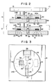
- Figs. 1 and 2 show the main section 10 of'a precision moving mechanism according to the invention.
- this section 10 comprises a first slight moving mechanism unit 12, a second slight moving mechanism unit 14 mounted on the unit 12 and having the same structure as the unit 12, and a turntable 16 supported by the second unit 14.
- the first slight moving mechanism unit 12 comprises a first base 18 and a first drive disk 22.
- the base 18 is a square plate.
- a ring 20 is formed on the upper surface of the base 18.
- the ring 20 has a smooth upper surface, on which the first drive disk 22 is mounted.
- the disk 22 consists of a first movable section 24a and a second movable section 24b, both being semicircular plates, and a resilient hinge 26 connecting the center portions of these sections 24a and 24b.
- the disk 22 is made by cutting two slits 28 and 30 in a disk, which extend in opposing radial directions and do not reach the center of the disk. That portion of the disk, which is left between the closed ends of these slits 28 and 30 is the resilient hinge 26.
- the two halves, which are separated by the slits 28 and 30, are the first and second movable sections 24a and 24b.
- a hole 32 is cut in the lower surface of the hinge 26.
- the base 18 has a through hole 34. This hole 34 is coaxial with the hole 32.
- a shaft 36 is fitted in the hole 34 and protrudes into the hole 32. Hence, the drive disk 22 may rotate around this shaft.
- the slit 30 has an inner, narrow portion and an outer, broad portion.
- a first piezoelectric element 38 made of zirconium titanate, lead titanate, or the like, is put in the outer portion of the slit 30.
- the element 38 is shaped like a rod and secured at one end to the first movable section 24a and at the other end to the second movable section 24b, by means of adhesive, screws, etc. Alternatively, holes may be cut in the opposing faces of the sections 24a and 24b, and the end portions of the elements 38 may be fitted in these holes. As illustrated in Fig. 2, two square recesses 40 and 42 are cut in the lower surfaces of the movable sections 24a and 24b, and open to the ring member 20. Two electrostatic chucks 44 and 46 (i.e., first and second members) are held within these recesses 40 and 42, respectively.
- the chuck 44 consists of an electrode 48 and an insulative member 52 wrapping the electrode 48.
- the chuck 46 consists of an electrode 50 and an insulative member 54 wrapping the electrode 50.
- the chuck 44 is energized to attach the first movable section 24a to the first base 18, and the chuck 46 is energized to attach the second movable section 24b to the base 18.
- a support 56 is secured, at its lower end, to the upper surface of the second movable section 24b. The upper end of this support 56 is fastened to that portion of a second base 58 which deviates from the center of rotation of the base 58.
- the second slight moving mechanism unit 14 is structurally identical with the first unit 12, except that the second base 58 is a disk, unlike the first base 18 that is a square plate.
- the base 58 is coaxial with the shaft 36.
- the unit 14 comprises a ring member 60 formed on the upper surface of the base 58, and a second drive disk 62 mounted on the ring member 60.
- the disk 62 consists of third and fourth movable sections 64a and 64b, and a resilient hinge 66 connecting these sections 64a and 64b.
- the unit 14 further comprises a shaft 72, a second piezoelectric element 74, two electrostatic chucks 76 and 78, and a support 80.
- the shaft 72 is fitted in a center hole of the base 58, positioned coaxially with the shaft 36 and supporting the drive disk 62.
- the element 74 is placed in the slit 70 of the disk 62.
- the chucks 76 and 78 i.e., third and fourth members
- the support 80 is secured at one end to the movable section 64b and at the other end to the turntable 16.
- the precision moving mechanism When the precision moving mechanism is used in an electron beam exposure apparatus, a reduced image projection apparatus or an X-ray image transfer apparatus, it is desired that the turntable 16, bases 18 and 58, drive disks 22 and 62 and other associated parts be made of nonmagnetic materials such as beryllium copper, aluminum and titanium. These parts, if made of nonmagnetic materials, do not adversely influence the magnetic field, which is necessary in these apparatus, so that patterns may be drawn on or transferred to a sample with a high precision.
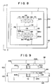
- Fig. 4 schematically shows the precision moving mechanism.
- the piezoelectric elements 38 and 74 and the electrodes of the chucks 44, 46, 76 and 78 are connected to a driver unit 82.
- This driver unit 82 is connected to a controller 84 made of a microcomputer or the like.
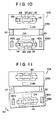
- a start signal Sl is supplied to the controller 84 at time t 0 .
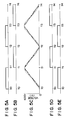
- the driver unit 82 starts and applies a voltage signal (Fig. 5A) to the electrostatic chuck 44. Simultaneously, it supplies a voltage signal (Fig 5E) to the electrostatic chuck 78.
- Fig. 5A a voltage signal
- Fig 5E a voltage signal
- the first movable section 24a is attached to the first base 18, and the fourth movable section 64b is attached to the second base 58.
- the driver unit 82 starts applying the voltage shown in Fig. 5C to the piezoelectric element 38.
- the drive disks 22 and 62 take the positions shown in Fig. 6A during a period T, time to to time t l .
- the turntable 16 rotates from the position indicated by a broken-line arrow 86 to the position indicated by a solid-line arrow 88.
- the voltage applied to the element 38 reaches its maximum as shown in Fig. 5C.
- any electrostatic chuck that is energized is indicated by a solid line
- any electrostatic chuck that is deenergized is indicated by a broken line.
- the voltage application to the chuck 44 is stopped as shown in Fig. 5A.
- the voltage application to the chuck 46 is started as shown in Fig. 5B.
- the voltage application to the chuck 78 is stopped as shown in Fig. 5E, and the voltage application to the chuck 76 is started as shown in Fig. 5D.
- the movable sections 24b and 64a are attached to the base plates 18 and 58 at time t l .
- the voltage applied to the element 38 starts falling stepwise at time t l .
- a voltage (Fig. 5F) is applied to the element 74.
- the movable section 64a is attached to the base 58 at this time, and the disk 62 is rotatable about the shaft 72. Therefore, the movable section 64b rotates counterclockwise by a very small angle. Since the section 64b is coupled to the table 16 by the support 80, the turntable 16 is rotated in the same direction by a small angle.
- the voltage application to the chuck 46 is stopped as illustrated in Fig. 5B.
- the voltage application to the chuck 44 is started as shown in Fig. 5A
- the voltage application to the chuck 76 is stopped as shown in Fig. 5D
- the voltage application to the chuck 78 is started as shown in Fig. 5E. Consequently, the movable sections 24a and 64b are attached to the bases 18 and 58.
- the voltage applied to the piezoelectric element 38 starts rising stepwise as shown in Fig. 5C
- the voltage applied to the element 74 begins to fall stepwise as shown in Fig. 5F.
- the element 38 therefore expands.
- the movable section 24a is attached to the base 18, and the movable section 24b is rotatable at this time. Hence, the section 24b rotates counterclockwise by a very small angle. This rotation is transmitted to the turntable 16 through the support 56, base 58, movable section 64b now attached to the base 58, and support 80. The turntable 16 therefore rotates coulterclockwise by a very small angle.
- the piezoelectric element 74 begins to contract. Since the section 64a is rotatable at this time, it is rotated counterclockwise by the restoring force of the resilient hinge 66, thus taking the initial positional relation with the movable section 64b (Fig. 6C). The rotation of the section 64a is not transmitted to the turntable 16.
- the voltages applied to piezoelectric elements 38 and 74 have a phase difference of 180°. Therefore, one of these elements expands, while the other contracts.
- the turntable 16 continues to rotate. The voltages are applied to the elements until the turntable rotates to the position specified by the data input to the controller 84.
- Fig. 6D illustrates the positional relation that the drive disks 22 and 62 take immediately before time t 4 , and the angle of rotation of the table 16 at time t 4 .
- the order in which the electrostatic chucks are energized may be reversed and the phase relation of the voltages applied to the elements 38 and 74 may be altered, so as to rotate the turntable 16 clockwise.
- the mechanism can rotate a sample two times faster than the conventional precision moving mechanism when the piezoelectric elements expand and contract at the same frequency. Unlike the known mechanism, it can move a sample at high speed without causing the piezoelectric elements to expand and contract more frequently.
- a voltage whose waveform is triangular and which stepwise rises and falls is applied to each piezoelectric element.
- This voltage may be replaced by a voltage which changes along sine waves as indicated by chain lines in Figs. 5C and 5F.
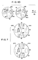
- a piezoelectric element is placed in only one of the slits of each drive disk.
- a third piezoelectric element 90 may be arranged in the slit 28 of the drive disk 22, and a fourth piezoelectric element 92 may be provided in the slit 68 of the drive disk 62.
- This embodiment operates in the same way as the mechanism of Figs. 1 to 4, when voltages are applied to the four piezoelectric elements in the following manner. First, a rising voltage is applied to the element 38 to make it expand, while a falling voltge is applied to the element 90 to make it contract. A falling voltage is then applied to the element 38, while a rising voltage is applied to the element 90. This two-step voltage application is repeated. Rising and falling voltages are applied to the elements 74 and 92 attached to the drive disk 62, exactly in the same manner as in the case of the elements 38 and 90. The four piezoelectric elements alternately expand and contract, thereby rotating the turntable 16 continuously.
- the main section 98 of this precision moving mechanism comprises a first slight moving mechanism unit 100, a second slight moving mechanism unit 102 supported by the unit 100, and a table 104 supported by the unit 102.
- the first slight moving mechanism 100 comprises a first base 106 and a first drive plate 108 mounted on the base 106.
- first drive plate 108 consists of a first movable section 109a and a second movable section 109b.
- These sections 109a and 190b are rectangular plates of the same size and positioned in the same plane side by side. They are connected to each other by a first piezoelectric element 110 and a third piezoelectric element 112. More specifically, the elements 110 and 112 are coupled at one end to one longer side of the movable section 109a and at the other end to that longer side of the movable section 109b which opposes said longer side of the section 109a.
- the sections 109a and 109b have rectangular holes 114 and 116 extending at right angles to the line along which the elements 110 and 112 expand and contract when voltages are applied to them.
- a first assist movable section 118 and a second assist movable section 120 are arranged in these holes 114 and 116, respectively.
- the sections 118 and 120 have a shape similar to that of the holes 114 and 116.
- Four resilient hinges 122 connect the assist movable section 118 to the longer inner edges of the hole 114.
- four resilient hinges 124 connect the assist movable section 120 to the longer edges of the hole 116.
- a piezoelectric element 126 is provided between the right end of the section 118 and the right shorter edge of the hole 114, and a piezoelectric element 128 is placed between the left end of the section 118 and the left shorter edge of the hole 114.
- a piezoelectric element 130 is provided between the right end of the section 120 and the right shorter edge of the hole 116, and a piezoelectric element 132 is provided between the left end of the section 120 and the left shorter edge of the hole 116.
- These elements 126, 128, 130 and 132 can expand and contract in the direction crossing the direction of the expansion and contraction of the first and third piezoelectric elements 110 and 112.
- Two electrostatic chucks 134 and 136 are secured to the lower surfaces of the movable sections 109a and 109b. Also, two electrostatic chucks 138 and 140 are secured to the lower surfaces of the assist movable sections 118 and 120.
- the movable section 109a is coupled to the base 146 of the second slight moving mechanism unit 102 by two supports 142a and 142b.
- the second slight moving mechanism unit 102 has almost the same structure as the first slight moving mechanism unit 100.
- it comprises the second base 146 and a second drive plate 148 mounted on the base 146.
- the plate 148 consists a third movable section 150a and a fourth movable section 150b.
- the sections 150a and 150b are coupled by second and fourth piezoelectric elements 152 and 154.
- the sections 150a and 150b have rectangular holes 156 and 158.
- a third assist moving section 160 is arranged in the hole 156, and a fourth assist moving section 162 is positioned in the hole 158.
- the section 160 is connected to the longer edges of the hole 156 by four resilient hinges 164.
- the section 162 is coupled to the longer edges of the hole 158 by four resilient hinges 166.
- a piezoelectric element 168 is provided between the right end of the section 160 and the right shorter edge of the hole 156, and a piezoelectric element 170 is placed between the left end of the section 160 and the left shorter edge of the hole 156.
- a piezoelectric element 172 is provided between the right end of the section 162 and the right shorter edge of the hole 158, and a piezoelectric element 174 is provided between the left end of the section 162 and the left shorter edge of the hole 158.
- Two electrostatic chucks 176 and 178 are secured to the lower surfaces of the sections 150a and 150b.
- Two more electrostatic chucks 180 and 182 are secured to the lower surfaces of the assist movable sections 160 and 162.
- the movable section 150a is coupled to the table 104 by a two support 184a and 184b.
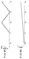
- the mechanism of Figs. 8 to 10 operates in the following way to rotate the table 104 continuously.
- the electrostatic chucks 136 and 176 are energized, thereby attaching the movable sections 109b and 150a to the bases 106 and 146.
- the piezoelectric elements 112 and 152 are made to expand, and the elements 110 and 154 are simultaneously made to contract, as illustrated in Fig. ll.
- the movable section 109a rotates by a very small angle, counterclockwise as indicated by arrow 191
- the movable section 150b rotates by a very small angle.
- the section 150a Since the section 150a is attached to the base 146, the rotation of the section 109a is transmitted to the table 104 through the base 146 and movable section 150a. The rotation of the movable section 150b is not transmitted to the table 104 since it is not coupled to the table 104 unlike the section 150a.
- the chucks 136 and 176 are deenergized, releasing the movable sections 109b and 150a from the bases 106 and 146, and the chucks 134 and 178 are energized, thus attaching the movable sections 109a and 150b to the bases 106 and 146.
- the elements 112 and 152 are made to contract, and the elements 110 and 154 are made to expand at the same time.
- the movable sections 109b and 150a rotate by a very small angle. Since the section 109a is attached to the base 106 during the second period, the rotation of only the section 150a is conveyed to the table 104.
- the table 104 continues to rotate counterclockwise.
- the order in which the electrostatic chucks are energized may be reversed, the phase relation of the voltages applied to the elements 110 and 112, and the phase relation of the voltages applied to the elements 152 and 154 may be altered, so as to rotate the table 104 clockwise.
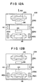
- the electrostatic chuck 134 is energized, thus attaching the movable section 109a to the base 106, and the piezoelectric elements 110 and 112 are made to expand, as illustrated in Fig. 13A.
- the section 109b thus moves from the position indicated by chain lines to the position indicated by solid lines.
- the electrostatic chuck 136 is energized, thereby attaching the movable section 109b to the base 100.
- the elements 110 and 112 are made to contract as shown in Fig. 12B.
- the movable section 109a therefore moves from the position indicated by chain lines to the position indicated by solid lines.
- the movable section 109a which is coupled to the base 146 by supports 142a and 142b, and the movable section 109b do not move during the first period and do move during the second period. That is to say, they intermittently move.
- the movable sections 150a and 150b are very slightly moved. While these sections 150a and 150b are at rest, the sections 109a and 109b are very slightly moved. Consequently, the table 104 is continuously moved in the direction of arrow 192 shown in Fig. 12A, or in the opposite direction.
- the electrostatic chucks 134 and 136 are energized, thus attaching the movable sections 109a and 109b to the base 106 as shown in Fig. 13A.
- the elements 126 and 130 are made to expand, and the elements 128 and 132 are made to contract.
- the assist movable sections 118 and 120 move very slightly to the left as shown in Fig. 13A.
- the resilient hinges 122 and 124 are deformed.
- the chucks 134 and 136 are deenergized, thus releasing the sections 109a and 109b from the base 106, and the chucks 138 and 140 are energized, thus attaching the assist movable sections 118 and 132 to the base 106.
- the elements 126 and 130 are made to contract, whereas the elements 128 and 132 are made to expand.
- the sections 109a and 109b move from the positions indicated by chain lines to the positions indicated by solid lines, as shown in Fig. 13B.
- the section 109a which is coupled to the base 146 by the supports 142a and 142b, and the section 109b are immovable during the first period and move very slightly during the second period.
- the precision moving mechanism of this invention unlike with the conventional mechanism, it is possible to rotate or move a table continuously and at high speed without actuating piezoelectric elements very frequently.
- a simple and inexpensive power source can therefore be used to apply voltages to the piezoelectric elements. Since the table is rotated or moved by the expansion and contraction of the piezoelectric elements, which can be precisely controlled electrically, the table can be moved to any position and stopped at it.
- the mechanism is simple in structure and does not require such parts as may easily be broken or deformed. Hence, it is reliable enough to be used in measuring apparatus or in apparatus for manufacturing semiconductor devices. Since all the parts of this mechanism can be made of nonmagnetic material, the mechanism can reliably function even if used in apparatus which use charged particles in the form of an electron beam or an ion beam.
- the present invention is not limited to the embodiments described above.
- the electrostatic chucks used to selectively attach the movable sections to the bases may be replaced by vacuum chucks or electromagnetic chucks.
- the driving unit for the piezoelectric elements may be constructed in various ways to suit the use. For example, it may be constructed such that a high voltage may be applied when it is desired to cause a very rough motion while a low voltage may be applied when it is desired to cause a fine motion.
- various changes and modifications can be made within the scope of the present invention.
Landscapes
- Chemical & Material Sciences (AREA)
- Analytical Chemistry (AREA)
- General Electrical Machinery Utilizing Piezoelectricity, Electrostriction Or Magnetostriction (AREA)
- Exposure And Positioning Against Photoresist Photosensitive Materials (AREA)
Applications Claiming Priority (2)
| Application Number | Priority Date | Filing Date | Title |
|---|---|---|---|
| JP130539/84 | 1984-06-25 | ||
| JP59130539A JPH0614789B2 (ja) | 1984-06-25 | 1984-06-25 | テーブル微動方法およびこの方法を用いた微動装置 |
Publications (3)
| Publication Number | Publication Date |
|---|---|
| EP0166499A2 true EP0166499A2 (de) | 1986-01-02 |
| EP0166499A3 EP0166499A3 (en) | 1987-05-13 |
| EP0166499B1 EP0166499B1 (de) | 1990-05-02 |
Family
ID=15036702
Family Applications (1)
| Application Number | Title | Priority Date | Filing Date |
|---|---|---|---|
| EP85301092A Expired EP0166499B1 (de) | 1984-06-25 | 1985-02-19 | Präzisionsbewegungsmechanismus |
Country Status (4)
| Country | Link |
|---|---|
| US (1) | US4585969A (de) |
| EP (1) | EP0166499B1 (de) |
| JP (1) | JPH0614789B2 (de) |
| DE (1) | DE3577495D1 (de) |
Cited By (5)
| Publication number | Priority date | Publication date | Assignee | Title |
|---|---|---|---|---|
| US4746800A (en) * | 1986-03-27 | 1988-05-24 | Asm Lithography B.V. | Positioning device comprising a z-manipulator and a θ-manipulator |
| US4785177A (en) * | 1986-03-27 | 1988-11-15 | Kernforschungsanlage Julich Gesellschaft Mit Beschrankter Haftung | Kinematic arrangement for the micro-movements of objects |
| WO1988009945A1 (en) * | 1987-06-04 | 1988-12-15 | Renishaw Plc | Positioning apparatus particularly for use in a vacuum environment |
| WO1991009428A1 (de) * | 1989-12-16 | 1991-06-27 | Teldix Gmbh | Schrittmotor zum antrieb eines körpers, insbesondere einer welle, um kleine drehwinkel pro schritt |
| US5325010A (en) * | 1988-07-03 | 1994-06-28 | Forschungszentrum Julich Gmbh | Micromanipulator |
Families Citing this family (18)
| Publication number | Priority date | Publication date | Assignee | Title |
|---|---|---|---|---|
| JPH0648910B2 (ja) * | 1987-02-12 | 1994-06-22 | 日本電気株式会社 | 圧電モ−タ |
| JPH0295180A (ja) * | 1988-09-29 | 1990-04-05 | Canon Inc | 尺取り虫型駆動機構 |
| US4968914A (en) * | 1989-03-24 | 1990-11-06 | Quanscan, Inc. | High resolution electromechanical translation device |
| US5631824A (en) * | 1994-05-26 | 1997-05-20 | Polytechnic University | Feedback control apparatus and method thereof for compensating for changes in structural frequencies |
| US6154000A (en) * | 1994-09-07 | 2000-11-28 | Omnitek Research & Development, Inc. | Apparatus for providing a controlled deflection and/or actuator apparatus |
| US5604413A (en) * | 1994-09-07 | 1997-02-18 | Polytechnic University | Apparatus for improving operational performance of a machine or device |
| US5751090A (en) * | 1995-05-17 | 1998-05-12 | Burleigh Instruments Inc | Peristaltic driver apparatus |
| TW360115U (en) * | 1998-03-12 | 1999-06-01 | Ind Tech Res Inst | Micro-positioning platform |
| GB2369489B (en) * | 2000-11-23 | 2004-03-10 | Khaled Karrai | Inertial rotation device |
| DE10224019B4 (de) * | 2002-05-24 | 2006-02-23 | Leibniz-Institut für Festkörper- und Werkstoffforschung e.V. | Drehbare Probenträgeraufnahmevorrichtung |
| NL1022886C2 (nl) * | 2003-03-10 | 2004-09-14 | Fei Co | Deeltjes optische inrichting voor het bestralen van een object. |
| EP1619468A1 (de) * | 2004-07-22 | 2006-01-25 | Leica Geosystems AG | Geodätisches Messgerät mit Piezo-Antrieb |
| DE102004054359B4 (de) * | 2004-11-10 | 2015-11-05 | Fraunhofer-Gesellschaft zur Förderung der angewandten Forschung e.V. | Vorrichtung zur Erzeugung einer Torsionsbewegung und Verwendung derselben |
| WO2010051797A2 (de) * | 2008-11-10 | 2010-05-14 | Richter, Berta | Elektrischer piezomotor-universalantrieb |
| JP2010162487A (ja) * | 2009-01-16 | 2010-07-29 | Sony Corp | 圧電振動機器システムおよび電子機器 |
| CN102141739B (zh) * | 2011-04-01 | 2013-01-16 | 清华大学 | 光刻机硅片台双台交换系统 |
| CN102508414B (zh) * | 2011-11-12 | 2013-09-18 | 哈尔滨工业大学 | 一种基于转台齿轮同步调向的双工件台回转交换方法与装置 |
| KR102396865B1 (ko) * | 2021-12-08 | 2022-05-12 | 주식회사 미코세라믹스 | 정전척 |
Family Cites Families (8)
| Publication number | Priority date | Publication date | Assignee | Title |
|---|---|---|---|---|
| US3684904A (en) * | 1969-04-24 | 1972-08-15 | Gennady Vasilievich Galutva | Device for precision displacement of a solid body |
| JPS5112497B1 (de) * | 1971-04-21 | 1976-04-20 | ||
| JPS5315060A (en) * | 1976-07-28 | 1978-02-10 | Hitachi Ltd | Inching device |
| SU871845A1 (ru) * | 1980-02-19 | 1981-10-15 | За витель А. П. Плешко | Пъезоэлектрический вибратор |
| US4455501A (en) * | 1982-02-09 | 1984-06-19 | Tokyo Shibaura Denki Kabushiki Kaisha | Precision rotation mechanism |
| JPS58139681A (ja) * | 1982-02-09 | 1983-08-19 | Toshiba Corp | 回転微動機構 |
| US4399386A (en) * | 1982-02-11 | 1983-08-16 | Rca Corporation | Rotative motor using plural arrays of piezoelectric elements |
| JPS5976184A (ja) * | 1982-10-22 | 1984-05-01 | Hitachi Ltd | アクチユエ−タ |
-
1984
- 1984-06-25 JP JP59130539A patent/JPH0614789B2/ja not_active Expired - Lifetime
-
1985
- 1985-02-15 US US06/702,074 patent/US4585969A/en not_active Expired - Fee Related
- 1985-02-19 EP EP85301092A patent/EP0166499B1/de not_active Expired
- 1985-02-19 DE DE8585301092T patent/DE3577495D1/de not_active Expired - Lifetime
Cited By (5)
| Publication number | Priority date | Publication date | Assignee | Title |
|---|---|---|---|---|
| US4746800A (en) * | 1986-03-27 | 1988-05-24 | Asm Lithography B.V. | Positioning device comprising a z-manipulator and a θ-manipulator |
| US4785177A (en) * | 1986-03-27 | 1988-11-15 | Kernforschungsanlage Julich Gesellschaft Mit Beschrankter Haftung | Kinematic arrangement for the micro-movements of objects |
| WO1988009945A1 (en) * | 1987-06-04 | 1988-12-15 | Renishaw Plc | Positioning apparatus particularly for use in a vacuum environment |
| US5325010A (en) * | 1988-07-03 | 1994-06-28 | Forschungszentrum Julich Gmbh | Micromanipulator |
| WO1991009428A1 (de) * | 1989-12-16 | 1991-06-27 | Teldix Gmbh | Schrittmotor zum antrieb eines körpers, insbesondere einer welle, um kleine drehwinkel pro schritt |
Also Published As
| Publication number | Publication date |
|---|---|
| JPH0614789B2 (ja) | 1994-02-23 |
| EP0166499A3 (en) | 1987-05-13 |
| DE3577495D1 (de) | 1990-06-07 |
| US4585969A (en) | 1986-04-29 |
| EP0166499B1 (de) | 1990-05-02 |
| JPS6110971A (ja) | 1986-01-18 |
Similar Documents
| Publication | Publication Date | Title |
|---|---|---|
| US4585969A (en) | Precision rotary moving mechanism using piezoelectric drive elements | |
| US5015906A (en) | Electrostatic levitation control system for micromechanical devices | |
| US6198180B1 (en) | Micromechanisms with floating pivot | |
| US5132582A (en) | Recording medium transferring apparatus and vibrating element used therein | |
| EP0633616B1 (de) | Keramischer Motor | |
| US3952215A (en) | Stepwise fine adjustment | |
| US4455501A (en) | Precision rotation mechanism | |
| JP2004500252A (ja) | 多層自己整列型垂直櫛形ドライブ静電アクチュエータ及びその製造方法 | |
| US5418418A (en) | Micro-actuator | |
| Fan et al. | Electrostatic microactuator and design considerations for HDD applications | |
| EP0143549B1 (de) | Genauer Drehmechanismus zur geringen Drehung eines Gegenstandes | |
| EP0160707B1 (de) | Piezoelektrischer Rotationsschrittantrieb | |
| JPH0373236B2 (de) | ||
| JPH10293979A (ja) | 剪断型圧電素子を用いたアクチュエータ及びこのアクチュエータを使用したヘッド微小移動機構 | |
| JP3677604B2 (ja) | 磁気アクチュエータ | |
| WO2004036727A2 (en) | Piezoelectric driving apparatus | |
| JPS6044838B2 (ja) | 回転微動機構 | |
| JP3183319B2 (ja) | 静電アクチュエータ | |
| JP3173261B2 (ja) | 静電アクチュエータ | |
| JPH0381119B2 (de) | ||
| JPH0527034Y2 (de) | ||
| JPH041512B2 (de) | ||
| JPH05185383A (ja) | 多自由度アクチュエータ | |
| JPH0365082A (ja) | 静電モータ | |
| JPH011481A (ja) | 圧電アクチュエ−タ− |
Legal Events
| Date | Code | Title | Description |
|---|---|---|---|
| PUAI | Public reference made under article 153(3) epc to a published international application that has entered the european phase |
Free format text: ORIGINAL CODE: 0009012 |
|
| 17P | Request for examination filed |
Effective date: 19850225 |
|
| AK | Designated contracting states |
Designated state(s): DE FR GB NL |
|
| PUAL | Search report despatched |
Free format text: ORIGINAL CODE: 0009013 |
|
| AK | Designated contracting states |
Kind code of ref document: A3 Designated state(s): DE FR GB NL |
|
| 17Q | First examination report despatched |
Effective date: 19881025 |
|
| GRAA | (expected) grant |
Free format text: ORIGINAL CODE: 0009210 |
|
| AK | Designated contracting states |
Kind code of ref document: B1 Designated state(s): DE FR GB NL |
|
| PG25 | Lapsed in a contracting state [announced via postgrant information from national office to epo] |
Ref country code: NL Effective date: 19900502 |
|
| REF | Corresponds to: |
Ref document number: 3577495 Country of ref document: DE Date of ref document: 19900607 |
|
| ET | Fr: translation filed | ||
| NLV1 | Nl: lapsed or annulled due to failure to fulfill the requirements of art. 29p and 29m of the patents act | ||
| PLBE | No opposition filed within time limit |
Free format text: ORIGINAL CODE: 0009261 |
|
| STAA | Information on the status of an ep patent application or granted ep patent |
Free format text: STATUS: NO OPPOSITION FILED WITHIN TIME LIMIT |
|
| 26N | No opposition filed | ||
| PGFP | Annual fee paid to national office [announced via postgrant information from national office to epo] |
Ref country code: FR Payment date: 19960125 Year of fee payment: 12 |
|
| PGFP | Annual fee paid to national office [announced via postgrant information from national office to epo] |
Ref country code: GB Payment date: 19960212 Year of fee payment: 12 |
|
| PGFP | Annual fee paid to national office [announced via postgrant information from national office to epo] |
Ref country code: DE Payment date: 19960227 Year of fee payment: 12 |
|
| PG25 | Lapsed in a contracting state [announced via postgrant information from national office to epo] |
Ref country code: GB Effective date: 19970219 |
|
| GBPC | Gb: european patent ceased through non-payment of renewal fee |
Effective date: 19970219 |
|
| PG25 | Lapsed in a contracting state [announced via postgrant information from national office to epo] |
Ref country code: FR Effective date: 19971030 |
|
| PG25 | Lapsed in a contracting state [announced via postgrant information from national office to epo] |
Ref country code: DE Effective date: 19971101 |
|
| REG | Reference to a national code |
Ref country code: FR Ref legal event code: ST |