EP0166460A2 - Tête optique pour mémoire magnéto-optique - Google Patents
Tête optique pour mémoire magnéto-optique Download PDFInfo
- Publication number
- EP0166460A2 EP0166460A2 EP85108077A EP85108077A EP0166460A2 EP 0166460 A2 EP0166460 A2 EP 0166460A2 EP 85108077 A EP85108077 A EP 85108077A EP 85108077 A EP85108077 A EP 85108077A EP 0166460 A2 EP0166460 A2 EP 0166460A2
- Authority
- EP
- European Patent Office
- Prior art keywords
- laser beam
- optical
- lens
- laser
- beam splitter
- Prior art date
- Legal status (The legal status is an assumption and is not a legal conclusion. Google has not performed a legal analysis and makes no representation as to the accuracy of the status listed.)
- Granted
Links
Images


Classifications
-
- G—PHYSICS
- G11—INFORMATION STORAGE
- G11B—INFORMATION STORAGE BASED ON RELATIVE MOVEMENT BETWEEN RECORD CARRIER AND TRANSDUCER
- G11B11/00—Recording on or reproducing from the same record carrier wherein for these two operations the methods are covered by different main groups of groups G11B3/00 - G11B7/00 or by different subgroups of group G11B9/00; Record carriers therefor
- G11B11/10—Recording on or reproducing from the same record carrier wherein for these two operations the methods are covered by different main groups of groups G11B3/00 - G11B7/00 or by different subgroups of group G11B9/00; Record carriers therefor using recording by magnetic means or other means for magnetisation or demagnetisation of a record carrier, e.g. light induced spin magnetisation; Demagnetisation by thermal or stress means in the presence or not of an orienting magnetic field
- G11B11/105—Recording on or reproducing from the same record carrier wherein for these two operations the methods are covered by different main groups of groups G11B3/00 - G11B7/00 or by different subgroups of group G11B9/00; Record carriers therefor using recording by magnetic means or other means for magnetisation or demagnetisation of a record carrier, e.g. light induced spin magnetisation; Demagnetisation by thermal or stress means in the presence or not of an orienting magnetic field using a beam of light or a magnetic field for recording by change of magnetisation and a beam of light for reproducing, i.e. magneto-optical, e.g. light-induced thermomagnetic recording, spin magnetisation recording, Kerr or Faraday effect reproducing
- G11B11/10532—Heads
Definitions
- This invention relates an optical head for a magneto-optical memory, and more particularly to an optical head which detects, with a high sensitivity, the direction of polarization rotating through a very small angle in a relation corresponding to the direction of magnetization of a perpendicular magnetic thin film, so that information recorded on the perpendicular magnetic thin film can be reproduced with a high S/N ratio.
- a magneto-optical disc memory is known as one of erasable (rewritable) optical information recording apparatus.
- An apparatus of this kind is described in, for example, N. Inamura and C. Ota; Japan J. Appl. Phys. 19 (1980) L731. According to the reported apparatus, information can be easily recorded and erased since the apparatus utilizes the light-induced thermo-magnetic effect. However, the reported apparatus, in which rotation, less than 1 degree, of the direction of polarization due to the magnetization is detected for reproducing recorded information, has had such a demerit that the quantity of reproduced signal light is very small, resulting in a low S/N ratio.
- a magneto-optical information recording and reproducing apparatus such as a magneto-optical disc memory
- its optical head must show a high extincition ratio so that slight rotation of the direction of polarization can be detected with a high sensitivity.
- the present invention is based on the finding of the relation between the optical anisotropy of a convergent lens (focusing lens) focusing a laser beam onto a magneto-optical recording medium (a perpendicular magnetic thin film) and the extinction ratio of an optical head and is featured by the fact that coincidence is attained between the major axis (the phase advance axis or phase lag axis) of optical anisotropy of the lens and the direction of linear polarization of the laser beam incident upon the lens, thereby improving the extincition ratio of the optical head.
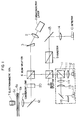
- Fig. 1 shows the structure of an embodiment of the optical head for a magneto-optical disc memory, according to the present invention.
- a divergent laser beam of elliptical cross-section emitted from a semiconductor laser device 1 is turned into a parallel beam by a collimating lens 2 of rotation symmetry configuration, and is then turned by a prism 3 into a parallel beam in which the beam intensity distribution in cross-section is circular, i.e. isotropic.
- the prism 3 is provided for tuning the incident beam into a parallel beam of circular cross-section as described above.
- the optical element in the system for providing such a beam configuration is in no way limited to the prism, and at least one cylindrical lens can also be used for that purpose.
- the numerical aperture of the collimating lens 2 may be suitably selected so that the collimating lens 2 can single provide the parallel beam of circular cross-section.
- the parallel beam After passing through a beam splitter (a palarizing prism) 4, the parallel beam is converged by a focusing lens 5 of rotation symmetry configuration into a bean spot of diffraction limit which is incident upon a magneto-optical disc 6 including a recording film (a perpendicular magnetic thin film) 6a.
- the magneto-optical disc 6 is adapted to be rotated by a drive motor (not shown).
- the magneto-optical disc 6 is comprised of a transparent substrate 6b, a recording film 6a and a protective layer 6c.
- the recording film 6a is in the form of a perpendicular magnetic thin film whose principal component is, for example, Tb-Te and which has a thickness of about 1,000 ⁇ .
- the protective layer 6c covering the recording film 6a is formed of, for 0 example, Si0 2 and has a thickness of about 1,400 A.
- spiral or concentric guide tracks (not shown) of phase structure acting as an optical guide for the beam spot may be provided on the recording film 6a with a pitch of, for example, 1.6 ⁇ m, when so required.
- each guide track is divided into many sectors.
- Each of the individual sectors includes a header part and a data recording part.
- contents required for management of information in the specific sector are provided in the form of, for example, a phase structure (concave and convex pits), as required and include the sector mark indicating the head of the specific sector, the synchronizing signal and the address such as the track number and the sector number used for the indentification of the specific sector.
- information is recorded by mangetization.
- the header information may be provided in the guide tracks or on the flat area between the guide tracks.
- An electromangetic coil 7 is disposed opposite to the disc 6 for applying a recording and erasing magnetic field.
- the convergent lens (focusing lens) 5 is mounted on a voice coil (not shown) so as to be moved to follow up vertical deflection of the disc 6.
- a mirror 12, such as, for example, a galvano-mirror is provided so that the beam spot can be shifted to follow up any eccentiricity of the disc 6.
- the drive current driving the semiconductor laser device 1 is modulated by an information signal to be recorded.
- the beam pulse signal corresponding to the information to be recorded is directed toward and onto the perpendicular magnetic thin film 6a of the disc 6 thereby locally raising the temperature of the perpendicular magnetic thin film 6a.
- the magnetization of the perpendicular magnetic thin film disappears locally.
- a magnetic field whose direction is opposite to the direction of magnetization of the surrounding magnetized portion is applied from the electromagnetic coil 7 to the portion from which the magnetization has disappeared locally, so that a domain (a magnetization domain) having the magnetization of the opposite direction is formed in the irradiated portion only.
- the process of erasing information recorded or written already on the perpendicular magnetic thin film by magnetization includes supplying a constant current to the semiconductor laser device 1 to direct the laser beam toward and onto the perpendicular magnetic thin film 6a thereby causing the magnetization of the magnetic thin film to disappear once, and, then, applying a magnetic field of the direction opposite to the direction applied by the electromagnetic coil 7 in the record mode, thereby restoring the direction of magnatiza- tion of the perpendicular magnetic thin film to the same direction as that of the surrounding non-recorded area.
- the Kerr effect is such that, depending on whether the direction of magnetization of the perpendicular magnetic thin film is upward or downward, the direction of polarization of the incident beam rotates slightly in opposite directions respectively.
- the beam reflected from the disc 6 passes through the convergent lens (focusing lens) 5 again and, after being split by the beam splitter 4 and then by another beam splitter 8, passed through an analyzer 9 to be reflected by a mirror 13.
- the beam reflected by the mirror 13 is guided through a lens 14 to a beam detector 10 which detects the magnetization information and the header signal.
- the analyzer 9 is an optical element which permits transmission of a specific polarized beam compent only.
- the beam passed through the beam splitter 8 is guided to an optical system 11 which detects the control signals used for the automatic focusing and tracking control.
- the beam passed through the beam splitter 8 is split into halves by another beam splitter 111.
- One of the split beams is guided through a spherical lens 112 to a half-split beam detector (two divided light detector) 113 which detects a tracking error singal, if any.
- the other beam passes through an astigmatic optical system composed of a shperical lens 114 and a cylindrical lens 115, and, after being partly shielded by a knife edge 116, is guided to another half-split beam detector (two divided light detector) 117 which detects a focusing error signal, if any. (Such a focusing signal detecting system is disclosed in, for example, U.S. Patent No. 4,450,547.)
- the differential output of the half-split beam detector (two divided light detector) 113 is detected by a tracking servo circuit (not shown), and the output of the tracking servo circuit is fed back to the mirror 12, which is a tracking actuator, for effecting the tracking control.
- the output of the half-split beam detector (two divided light detector) 117 is applied to an automatic focusing servo circuit (not shown), and the differential output of the automatic focusing servo circuit is fed back to the voice coil mounted on the convergent lens (focusing lens) 5, for effecting the focusing control.
- the header signal is also obtained from the sum output form the half-split beam detector (two divided light detector) 113.
- any one of the known methods is applicable to the optical head of the present invention.
- the combination of a cylindrical lens and a quarter-split beam detector (four divided light detector), as disclosed in U.S. Patent No. 4,293,944 may be used, so that the header signal, focusing signal and tracking signal can be detected by a single detection system.
- Such an optical head is so arranged that it can be wholly or partly shifted to any desired radial position of the disc 6 by a carriage motor such as a linear motor.
- Fig. 2 shows the principal parts extracted from Fig. 1. It is supposed that the laser beam emitted from the semiconductor laser device 1 is linearly polarized, and the irradiating laser beam passed through the polarization prism 4 is the P polarized beam polarized in the plane of the drawing sheet. The direction of polarization of the beam reflected from the perpendicular magnetic thin film 6a of the disc 6 is rotated by a Kerr rotation angle ⁇ ⁇ by the Kerr effect, and the polarized beam includes an S polarized beam component which is perpendicular to the plane of the drawing sheet.
- the direction of polarization of the beam rotates in opposite directions respectively depending on whether the direction of magnetization of the perpendicular magnetic thin film 6a is upward or downward. Therefore, when the beam reflected from the perpendicular magnetic thin film 6a is guided through the analyzer 9 to the beam detector 10, a change in the beam intensity is detected.
- Fig. 3 illustrates how the rotation of the direction of polarization is converted into a relative magnitude of the beam intensity by the analyzer 9.
- 8A designates the angle of rotation of the analyzer 9 from the extinction position S.
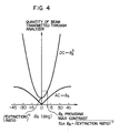
- the quantity of the beam transmitted through the analyzer 9 is given by the second power of the projected portion (the amplitude) of the electrical vector relative to the analyzer transmission axis. Therefore, the difference between the beams rotated throught the Kerr rotation angles +8 K and -6K in the opposite directions respectively, that is, the transmitted signal beam quantity S is given by the following expression:
- Fig. 4 is a graphic illustration of the expressions (1) and (2), and the horizontal axis represents the rotation angle ⁇ A .
- the S/N ratio becomes maximum when ⁇ A is selected to provide a largest AC/DC ratio, that is, a maximum contrast. From the expressions (1) and (2), the following equation is obtained:
- Fig. 5 is a graphic illustration of the dependence of the S/N ratio on the value of 8A when the signal S and the noise N are logarithmically expressed.
- Fig. 5 illustrates two cases of respectively different extinction ratios. It will be seen that the larger the extinction ratio and the smaller the (extinction ratio) -1 , the better is the S/N ratio. This is achieved when the direction of polarization of the incident polarized beam coincides with the optical anisotropic axis of the convergent lens (focusing lens) 5. When the direction of polarization of the incident polarized beam does not coincide with the optical anisotropic axis of the convergent lens (focusing lens) 5, the noise level rises, resulting in a lowered S/N ratio. It can be seen that the value of 6A providing the maximum S/N ratio becomes small.
- the extinction ratio of the optical head is an important factor for determining the S/N ratio. Selection of a good extinction ratio contributes to the improvement of the S/N ratio. The fact that the extinction ratio is determined by the optical anisotropy of the convergent lens (focusing lens) 5 will be proved on the basis of experimental date.
- Fig. 6 shows data obtained as a result of evaluation of the extinction ratio on the illustrated measuring system.
- the horizontal axis represents the rotation angle 6A of the analyzer
- the minimum value of I/Io increases, and the value of ⁇ A gaving the minimum value of I/Io is not zero. Further, rotaion of the focusing lens around the optical axis changes the extinction ratio.
- insertion of the focusing lens in the optical system leads to a worse extinction ratio, and the degree of worsening of the extinction ratio is dependent on whether the focusing lens is perfectly finished or not and dependent also on the angular position of rotation of the lens around the optical axis.
- Fig. 6 shows the results of measurment using two different focusing lenses.
- Fig. 7 is a graph in which the rotation angle of a certain focusing lens around the optical axis is plotted on the horizontal axis, and the (extrinction ratio) -1 is plotted on the vertical axis. It will be seen that rotation of the lens changes the value of the (extinction ratio) -1 .
- the result of checking on the state of polarization of the beam having transmitted through the convergent lens proves that the beam is no more linearly polarized but is elliptically polarized due to rotation of the major axis.
- This optical anisotropy of the lens is considered to be attributable to, for example, distortion of the glass body forming the lens and misalignment of the lens axis during assembling.
- the (extinction ratio) changes with the period of 180° in terms of the rotation angle of the focusing lens. It will also be seen that the (extinction ratio) -1 takes its minimum value with the period of about 90°. That is, the beam transmitted through the focusing lens advances in a state in which it is divided into a phase advance axis component and a phase lag axis component which are two oscillation components substantially orthogonal to each other, and, with the rotation of the focusing lens, the (extinction ratio) becomes minimum when coincidence is reached between the phase advance axis or phase lag axis of the lens and the direction of linear polarization of the incident laser beam.
- the (extinction ratio) changes with the period of 180° in terms of the rotation angle of the focusing lens.
- the (extinction ratio) -1 takes its minimum value with the period of about 90°. That is, the beam transmitted through the focusing lens advances in a state in which it is divided into a phase advance axis component and a phase lag axis component which are two oscillation components substantially orthogonal to
- an optical head having a small value of the (extinction ratio) -1 is obtained when the major axis (the phase advance axis or phase lag axis) of optical anisotropy of the focusing lens is selected to substantially coincide with the direction.of linear polarization of the incident laser beam, and information recorded by magnetization can be reproduced with a high S/N ratio.
- the optical anisotropy of the collimating lens 2 need not be strictly specified. This is because the beam splitter 4 reflects almost 100% of the S polarized beam and permits transmission of about 50% of the P polarized beam only, and the transmission of the linearly polarized beam through the beam splitter 4 improves the P : S ratio of the linearly polarized beam.
- the focusing lens 5 is rotated around the center of the optical axis of the optical system to attain coincidence between the major axis of optical anisotropy of the lens and the direction of linear polarization of the incident laser beam.
- the coincidence therebetween can also be attained by rotating the direction of linear polarization of the incident laser beam.
- a a/2 plate 20 (where ⁇ is the wavelength) as shown by dotted lines in Fig. 1 is interposed between the beam splitter 4 and the focusing lens 5.
- This ⁇ /2 plate 20 is rotated around the center of the optical axis of the optical system to cause rotation of the direction of linear polarization of the laser beam incident upon the focusing lens 5 until the direction of linear polarization of the incident laser beam coincides substantially with the major axis of optical anisotropy of the convergent lens 5.
- the direction of linear polarization of the linearly polarized beam transmitted through the beam splitter 4 is caused to coincide with the major axis of optical anisotropy of the focusing lens 5 by the function of the a/2 plate 20, and such a laser beam is focused by the focusing lens 5 onto the disc 6 as a beam spot.
- the beam reflected from the disc 6 passes through the focusing lens 5 and X/2 plate 20 again and is then reflected by the polarized beam splitter 4. After being then reflected by the polarized beam splitter 8, the beam is guided through the analyzer 9 to the beam detector 10.
- Fig. 8 illustrates the state of polarization when the laser beam, whose direction of linear polarization P is caused to coincide with the optical anisotropic axis of the convergent lens (focusing lens) 5 by the function of the a/2 plate 20, is reflected from the disc 6.
- the direction of linear polarization of the laser beam transmitted through the polarized beam splitter 4 in Fig. 1 corresponds to P shown in Fig. 8.
- the optical anisotropic axis (the phase advance axis or phase lag axis) of the focusing lens 5 makes an angle of ⁇ p with the direction of linear polarization P.
- the crystallographic axis of the a/2 plate 20 is selected to make an angle of ⁇ p /2 with the direction of polarization P, coincidence is reached between the direction of linear polarization of the incident laser beam and the optical anisotropic axis of the lens 5, and such a laser beam is focused by the lens 5 to form a beam spot on the disc 6.
- the direction of polarization of the linearly polarized beam reflected from the disc 6 rotates by ⁇ K around the optical anisotropic axis of the focusing lens 5 depending on the direction of magnetization of the perpendicular magnetic thin film 6a of the disc 6.
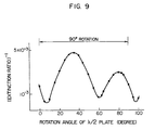
- Fig. 9 is a graph in which the rotation angle of the A/2 plate 20 around the optical axis is plotted on the horizontal axis, and the (extinction ratio) -1 is plotted on the vertical axis. It will be seen that the rotation of the a/2 plate 20 changes the value of the (extinction ratio) -1 , as in the case of Fig. 7. That is, the (extinction ratio) -1 changes with the period of about 90° in terms of the rotation angle of the ⁇ /2 plate 20, and becomes minimum with the period of about 45°.
- the ⁇ /2 plate 20 is so disposed as to make an angle of, for example, about 10° with the direction of linear polarization of the laser beam emitted from the simi- conductor laser device 1 and passed through the beam splitter 4, in the case of the example shown in Fig. 9, coincidence is substantially reached between the direction of linear polarization of the laser beam incident upon the focusing lens 5 and the major axis (the phase advance axis or phase lag axis) of optical anisotropy of the focusing lens 5.
- the major axis the phase advance axis or phase lag axis
Applications Claiming Priority (4)
| Application Number | Priority Date | Filing Date | Title |
|---|---|---|---|
| JP59133162A JPS6113462A (ja) | 1984-06-29 | 1984-06-29 | 光磁気ヘツド |
| JP133162/84 | 1984-06-29 | ||
| JP59211318A JPS6190346A (ja) | 1984-10-11 | 1984-10-11 | 光磁気再生装置 |
| JP211318/84 | 1984-10-11 |
Publications (3)
| Publication Number | Publication Date |
|---|---|
| EP0166460A2 true EP0166460A2 (fr) | 1986-01-02 |
| EP0166460A3 EP0166460A3 (en) | 1988-06-01 |
| EP0166460B1 EP0166460B1 (fr) | 1991-04-03 |
Family
ID=26467573
Family Applications (1)
| Application Number | Title | Priority Date | Filing Date |
|---|---|---|---|
| EP85108077A Expired - Lifetime EP0166460B1 (fr) | 1984-06-29 | 1985-06-28 | Tête optique pour mémoire magnéto-optique |
Country Status (4)
| Country | Link |
|---|---|
| US (1) | US4672593A (fr) |
| EP (1) | EP0166460B1 (fr) |
| KR (1) | KR920007294B1 (fr) |
| DE (1) | DE3582366D1 (fr) |
Cited By (1)
| Publication number | Priority date | Publication date | Assignee | Title |
|---|---|---|---|---|
| EP0372881A2 (fr) * | 1988-12-02 | 1990-06-13 | Mitsui Petrochemical Industries, Ltd. | Méthode de contrôle d'un signal de sortie optique et appareil à cet effet |
Families Citing this family (10)
| Publication number | Priority date | Publication date | Assignee | Title |
|---|---|---|---|---|
| JPS6185653A (ja) * | 1984-10-02 | 1986-05-01 | Sharp Corp | 光磁気メモリ素子 |
| US5249171A (en) * | 1984-12-30 | 1993-09-28 | Olympus Optical Company Ltd. | Opto-magnetic pick-up device including phase difference correcting means |
| JP2531626B2 (ja) * | 1986-04-10 | 1996-09-04 | オリンパス光学工業株式会社 | 光学的記録媒体用基盤の光学的特性測定装置 |
| JPH07101523B2 (ja) * | 1986-09-12 | 1995-11-01 | キヤノン株式会社 | 光磁気信号再生装置 |
| US4813032A (en) * | 1986-10-17 | 1989-03-14 | Canon Kabushiki Kaisha | Magneto-optical information reproducing apparatus in which the azimuth angle of the transmission axis of an analyzer is optimized so that the C/N ratio of a reproducing signal is maximum |
| JPH0677351B2 (ja) * | 1986-11-15 | 1994-09-28 | ソニー株式会社 | 光学ピツクアツプ装置 |
| US4918675A (en) * | 1986-12-04 | 1990-04-17 | Pencom International Corporation | Magneto-optical head with separate optical paths for error and data detection |
| US4905216A (en) * | 1986-12-04 | 1990-02-27 | Pencom International Corporation | Method for constructing an optical head by varying a hologram pattern |
| JPH0435222U (fr) * | 1990-07-23 | 1992-03-24 | ||
| WO1998027553A1 (fr) * | 1996-12-19 | 1998-06-25 | Matsushita Electric Industrial Co., Ltd. | Disque optique, procede d'enregistrement et lecture sur disque optique d'information non effaçable, dispositif de lecture de disque optique, dispositif d'enregistrement et lecture de disque optique, dispositif d'enregistrement d'information non effaçable sur disque optique et dispositif d'enregistrement de disque optique |
Citations (1)
| Publication number | Priority date | Publication date | Assignee | Title |
|---|---|---|---|---|
| EP0078673A2 (fr) * | 1981-10-29 | 1983-05-11 | Sharp Kabushiki Kaisha | Montage de tête magnéto-optique |
Family Cites Families (6)
| Publication number | Priority date | Publication date | Assignee | Title |
|---|---|---|---|---|
| JPS57147148A (en) * | 1981-03-05 | 1982-09-10 | Olympus Optical Co Ltd | Information reproducer with magnetooptic system |
| US4561032A (en) * | 1981-06-02 | 1985-12-24 | Canon Kabushiki Kaisha | Magnetooptic reproducing device |
| DE3376172D1 (en) * | 1982-01-22 | 1988-05-05 | Hitachi Ltd | Method and apparatus for reducing semiconductor laser optical noise |
| US4558440A (en) * | 1982-08-19 | 1985-12-10 | Canon Kabushiki Kaisha | System for recording patterns of magnetically recorded information by utilizing the magneto-optic effect |
| JPS5945646A (ja) * | 1982-09-07 | 1984-03-14 | Hitachi Ltd | 光学的情報再生装置 |
| JPS5963040A (ja) * | 1982-09-16 | 1984-04-10 | Canon Inc | 光磁気情報読取装置 |
-
1985
- 1985-06-25 KR KR1019850004501A patent/KR920007294B1/ko not_active IP Right Cessation
- 1985-06-28 EP EP85108077A patent/EP0166460B1/fr not_active Expired - Lifetime
- 1985-06-28 DE DE8585108077T patent/DE3582366D1/de not_active Expired - Lifetime
- 1985-07-01 US US06/750,476 patent/US4672593A/en not_active Expired - Lifetime
Patent Citations (1)
| Publication number | Priority date | Publication date | Assignee | Title |
|---|---|---|---|---|
| EP0078673A2 (fr) * | 1981-10-29 | 1983-05-11 | Sharp Kabushiki Kaisha | Montage de tête magnéto-optique |
Cited By (2)
| Publication number | Priority date | Publication date | Assignee | Title |
|---|---|---|---|---|
| EP0372881A2 (fr) * | 1988-12-02 | 1990-06-13 | Mitsui Petrochemical Industries, Ltd. | Méthode de contrôle d'un signal de sortie optique et appareil à cet effet |
| EP0372881A3 (fr) * | 1988-12-02 | 1991-05-29 | Mitsui Petrochemical Industries, Ltd. | Méthode de contrôle d'un signal de sortie optique et appareil à cet effet |
Also Published As
| Publication number | Publication date |
|---|---|
| US4672593A (en) | 1987-06-09 |
| DE3582366D1 (de) | 1991-05-08 |
| EP0166460B1 (fr) | 1991-04-03 |
| KR860000634A (ko) | 1986-01-29 |
| KR920007294B1 (ko) | 1992-08-29 |
| EP0166460A3 (en) | 1988-06-01 |
Similar Documents
| Publication | Publication Date | Title |
|---|---|---|
| US4985881A (en) | Record carrier for a magneto-optical disc memory having guide grooves of a plurality of tracks disposed with a predetermined relation to light spot diameter | |
| US5189655A (en) | Optical head for optical disk recording/reproducing apparatus including modified wollaston prism | |
| US4787076A (en) | Optical disc tracking system with switching of tracking error signals at boundary between track guide and track address | |
| US6363039B2 (en) | Disk tilting compensation with an offset signal to control the location of a light beam | |
| US4656618A (en) | Optical information recording and reproducing apparatus | |
| US4549287A (en) | System for recording and playing back information with magneto-optical disk memory using record and readout light beams of different wavelengths | |
| EP0166460B1 (fr) | Tête optique pour mémoire magnéto-optique | |
| US4695992A (en) | Optical information recording-reproducing apparatus in which the relative position of a primary beam and secondary beams on recording medium is varied during recording and reproduction of information | |
| US5490133A (en) | Optical information processing apparatus and method of controlling position of optical spot and reproducing signals | |
| US5903529A (en) | Optical pickup device and disk player apparatus | |
| US4977552A (en) | Split type optical pick-up device with a tracking error detector on the moving part | |
| JPH0581977B2 (fr) | ||
| EP0195227A2 (fr) | Mémoire à disque magnéto-optique | |
| US5119352A (en) | Magneto optic data storage read out apparatus and method | |
| JP3260771B2 (ja) | 光学焦点検出装置と光ビームの焦点を検出する方法 | |
| EP0324949A1 (fr) | Système de suivi de piste pour mémoire à disque optique | |
| JP2613921B2 (ja) | 光磁気メモリ装置 | |
| EP0555037B1 (fr) | Appareil d'enregistrement/reproduction d'information magnétooptique | |
| US5490129A (en) | Optical head and optical information reading apparatus | |
| JP2667678B2 (ja) | 光磁気メモリ装置 | |
| JP2859519B2 (ja) | 光情報再生装置 | |
| JPS6254857A (ja) | 光磁気情報記録装置 | |
| JPS6236760A (ja) | 記録再生方式 | |
| JPH0386953A (ja) | 光磁気記録再生装置 | |
| JPS6113462A (ja) | 光磁気ヘツド |
Legal Events
| Date | Code | Title | Description |
|---|---|---|---|
| PUAI | Public reference made under article 153(3) epc to a published international application that has entered the european phase |
Free format text: ORIGINAL CODE: 0009012 |
|
| AK | Designated contracting states |
Designated state(s): DE FR GB NL |
|
| PUAL | Search report despatched |
Free format text: ORIGINAL CODE: 0009013 |
|
| AK | Designated contracting states |
Kind code of ref document: A3 Designated state(s): DE FR GB NL |
|
| 17P | Request for examination filed |
Effective date: 19880603 |
|
| 17Q | First examination report despatched |
Effective date: 19891110 |
|
| GRAA | (expected) grant |
Free format text: ORIGINAL CODE: 0009210 |
|
| AK | Designated contracting states |
Kind code of ref document: B1 Designated state(s): DE FR GB NL |
|
| REF | Corresponds to: |
Ref document number: 3582366 Country of ref document: DE Date of ref document: 19910508 |
|
| ET | Fr: translation filed | ||
| PLBE | No opposition filed within time limit |
Free format text: ORIGINAL CODE: 0009261 |
|
| STAA | Information on the status of an ep patent application or granted ep patent |
Free format text: STATUS: NO OPPOSITION FILED WITHIN TIME LIMIT |
|
| 26N | No opposition filed | ||
| PGFP | Annual fee paid to national office [announced via postgrant information from national office to epo] |
Ref country code: FR Payment date: 20010418 Year of fee payment: 17 |
|
| PGFP | Annual fee paid to national office [announced via postgrant information from national office to epo] |
Ref country code: GB Payment date: 20010525 Year of fee payment: 17 |
|
| PGFP | Annual fee paid to national office [announced via postgrant information from national office to epo] |
Ref country code: NL Payment date: 20010630 Year of fee payment: 17 |
|
| PGFP | Annual fee paid to national office [announced via postgrant information from national office to epo] |
Ref country code: DE Payment date: 20010830 Year of fee payment: 17 |
|
| REG | Reference to a national code |
Ref country code: GB Ref legal event code: IF02 |
|
| PG25 | Lapsed in a contracting state [announced via postgrant information from national office to epo] |
Ref country code: GB Free format text: LAPSE BECAUSE OF NON-PAYMENT OF DUE FEES Effective date: 20020628 |
|
| PG25 | Lapsed in a contracting state [announced via postgrant information from national office to epo] |
Ref country code: NL Free format text: LAPSE BECAUSE OF NON-PAYMENT OF DUE FEES Effective date: 20030101 Ref country code: DE Free format text: LAPSE BECAUSE OF NON-PAYMENT OF DUE FEES Effective date: 20030101 |
|
| GBPC | Gb: european patent ceased through non-payment of renewal fee |
Effective date: 20020628 |
|
| PG25 | Lapsed in a contracting state [announced via postgrant information from national office to epo] |
Ref country code: FR Free format text: LAPSE BECAUSE OF NON-PAYMENT OF DUE FEES Effective date: 20030228 |
|
| NLV4 | Nl: lapsed or anulled due to non-payment of the annual fee |
Effective date: 20030101 |
|
| REG | Reference to a national code |
Ref country code: FR Ref legal event code: ST |