EP0166129B1 - Vorrichtung zum druckdichten Befestigen von Rohren in Rohrböden - Google Patents
Vorrichtung zum druckdichten Befestigen von Rohren in Rohrböden Download PDFInfo
- Publication number
- EP0166129B1 EP0166129B1 EP85105459A EP85105459A EP0166129B1 EP 0166129 B1 EP0166129 B1 EP 0166129B1 EP 85105459 A EP85105459 A EP 85105459A EP 85105459 A EP85105459 A EP 85105459A EP 0166129 B1 EP0166129 B1 EP 0166129B1
- Authority
- EP
- European Patent Office
- Prior art keywords
- pressure
- piston
- pressure piston
- low
- probe
- Prior art date
- Legal status (The legal status is an assumption and is not a legal conclusion. Google has not performed a legal analysis and makes no representation as to the accuracy of the status listed.)
- Expired
Links
- 239000000523 sample Substances 0.000 claims abstract description 28
- 238000000034 method Methods 0.000 description 4
- 238000007789 sealing Methods 0.000 description 4
- 238000010276 construction Methods 0.000 description 2
- 230000006378 damage Effects 0.000 description 2
- 230000000149 penetrating effect Effects 0.000 description 2
- 238000010521 absorption reaction Methods 0.000 description 1
- 230000015572 biosynthetic process Effects 0.000 description 1
- 238000010586 diagram Methods 0.000 description 1
- 238000005553 drilling Methods 0.000 description 1
- 230000002349 favourable effect Effects 0.000 description 1
- 238000003780 insertion Methods 0.000 description 1
- 230000037431 insertion Effects 0.000 description 1
- 239000000463 material Substances 0.000 description 1
- 230000001105 regulatory effect Effects 0.000 description 1
Images

Classifications
-
- B—PERFORMING OPERATIONS; TRANSPORTING
- B21—MECHANICAL METAL-WORKING WITHOUT ESSENTIALLY REMOVING MATERIAL; PUNCHING METAL
- B21D—WORKING OR PROCESSING OF SHEET METAL OR METAL TUBES, RODS OR PROFILES WITHOUT ESSENTIALLY REMOVING MATERIAL; PUNCHING METAL
- B21D39/00—Application of procedures in order to connect objects or parts, e.g. coating with sheet metal otherwise than by plating; Tube expanders
- B21D39/08—Tube expanders
- B21D39/20—Tube expanders with mandrels, e.g. expandable
- B21D39/203—Tube expanders with mandrels, e.g. expandable expandable by fluid or elastic material
-
- B—PERFORMING OPERATIONS; TRANSPORTING
- B21—MECHANICAL METAL-WORKING WITHOUT ESSENTIALLY REMOVING MATERIAL; PUNCHING METAL
- B21D—WORKING OR PROCESSING OF SHEET METAL OR METAL TUBES, RODS OR PROFILES WITHOUT ESSENTIALLY REMOVING MATERIAL; PUNCHING METAL
- B21D39/00—Application of procedures in order to connect objects or parts, e.g. coating with sheet metal otherwise than by plating; Tube expanders
- B21D39/06—Application of procedures in order to connect objects or parts, e.g. coating with sheet metal otherwise than by plating; Tube expanders of tubes in openings, e.g. rolling-in
Definitions
- the invention relates to a device for the pressure-tight fastening of tubes in tube sheets by widening the tube end lying inside the tube sheet with a probe which can be inserted into the respective tube end and which forms an annular space with the tube piece to be expanded by means of at least two seals arranged on the outer surface thereof and spaced apart from one another.
- a pressure intensifier arranged on the probe brings the pressure medium to the pressure required for the respective expansion process, the pressure intensifier comprising a low-pressure piston to which working medium can be applied and a high-pressure piston with a smaller piston area acting on the pressure medium in the annular space.
- a device of the type described above is known for example from DE-B-2 616 523.
- the high-pressure piston is connected to the low-pressure piston and protrudes with its front end into a cylinder housing which is connected via a high-pressure line to the jacket surface of the probe between the seals.
- the invention is therefore based on the object of facilitating the operation of a device of the type described above in that the pressure intensifier connected to the probe is made considerably smaller and lighter.
- the solution to this problem by the invention is characterized in that the low-pressure piston, which is displaceably guided in a housing, is provided with a central bore into which the high-pressure piston, which is fixedly connected to the housing, protrudes and which communicates with the jacket surface of the probe between the high-pressure piston and the high-pressure line the seals are connected.
- the design according to the invention eliminates the need for an additional housing for the high-pressure piston because it is formed by the low-pressure piston provided with the central bore. However, this not only achieves a spatial reduction in the pressure intensifier, but also a considerably more favorable absorption of the pressures prevailing in the high-pressure chamber.
- the high-pressure chamber formed by the bore in the low-pressure piston is in fact not only surrounded by the wall of the low-pressure piston, which is very strong because of the pressure area difference, but also by the wall of the housing in which the low-pressure piston is guided. Both components thus absorb the forces prevailing in the high-pressure chamber, so that lighter materials and smaller dimensions can be used for the pressure intensifier, which can therefore not only be made considerably smaller, but also considerably lighter.
- the end face of the low-pressure piston and / or the high-pressure piston are curved outwards and the counter surface of the housing or the bore in the low-pressure piston is correspondingly concave.
- the low-pressure piston is provided with a thick-walled extension of its piston jacket.
- the invention also proposes to design the extension of the low-pressure piston with conical stop surfaces for corresponding contact surfaces which are formed on that part of the housing which surrounds the high-pressure piston. This further development protects the pressure intensifier from damage or destruction if, for example, leaks in the annular space to be expanded cause the low-pressure piston to reach its end position within the housing.
- the housing is formed by a sleeve-shaped housing main part with the cylindrical guide surface for the low-pressure piston and by a housing front part carrying the high-pressure piston, to which the probe is also attached.
- a further simplification is obtained if a two-way valve is arranged in the front part of the housing, through which the high-pressure line can be connected either to an unpressurized reservoir or to the pressure line of a pump for the pressure medium.
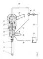
- the device for the pressure-tight fastening of tubes in tube sheets comprises a housing 1, which is formed by a sleeve-shaped housing main part 1a and a housing front part 1b, which are screwed together in the exemplary embodiment.
- a housing 1a In the main housing part 1a is one cylindrical guide surface 1c formed for a low-pressure piston 2, which is provided on its piston jacket with sealing rings 3.
- the piston surface 2a of the low-pressure piston 2 is curved outwards.
- the counter surface 1 d of the main housing part 1 a is concave.
- This high-pressure piston 4 is also provided with a plurality of sealing rings 5 in order to achieve a seal between the high-pressure piston 4 and the low-pressure piston 2.
- the high-pressure piston 4 is fixed on the housing 1. In the embodiment, it is made in one piece with the front housing part 1b. In the high-pressure piston 4 too, the piston surface 4a is curved outwards. The corresponding counter surface 2c in the base of the central bore 2b in the low-pressure piston 2 is again made concave.
- a probe 6 to be inserted into the pipe end to be widened is attached directly to the front part 1 b of the housing 1.
- two seals 7 are arranged which, after insertion of the probe 6 into a tube end lying inside a tube sheet, form an annular space with the pipe piece to be expanded and the lateral surface of the probe 6 lying between the seals 7, which is filled with pressure medium for expansion .
- the pressure of this pressure medium required for the respective expansion process is generated in the high-pressure chamber 3 of the pressure intensifier described above.
- the high-pressure chamber 8 is connected to the lateral surface of the probe 6 between the seals 7 via a high-pressure line 9 penetrating the high-pressure piston 4.
- this high-pressure line 9 consists of a longitudinal bore penetrating the high-pressure piston 4 and the front housing part 1 b and part of the probe 6.
- the main housing part 1a is provided with a pistol-like handle 10 in the exemplary embodiment.
- An additional handle 11 is attached to the front housing part 1.
- the drawing also schematically shows a circuit diagram for the pressure medium used for expanding.
- the illustration shows an unpressurized reservoir 12 for the pressure medium, which is connected via a suction line 13 to a pump 14.
- the pressure line 15 of this pump 14 leads to the main housing part 1a in order to apply pressure medium to the piston surface 2a of the low-pressure piston 2.
- a switchover valve 16 is arranged in the pressure line 15 of the pump 14, via which the pressure line 15 can be connected to the high-pressure chamber 8 leading to the high-pressure chamber 8 in the front part 1b of the housing.
- the connection takes place with the aid of a connecting line 17 and a two-way valve 18 which is arranged in the front housing part 1b.
- the pump 14 sucks pressure medium from the reservoir 12 via the suction line 13 and supplies it to the two-way valve 18 via the pressure line 15, the changeover valve 16 and the connecting line 17.
- This two-way valve 18 establishes the connection with the high-pressure line 9, so that both the annular space sealed by the seals 7 around the probe 6 and the high-pressure space 8 of the pressure booster are filled with pressure medium.
- the low-pressure piston 2 is moved into its starting position shown in the drawing.
- the changeover valve 16 is then brought into the position shown in the drawing, in which it connects the pump 14 to the piston surface 2 a of the low-pressure piston 2.
- the low-pressure piston 2 is moved to the left in the drawing. This movement causes an increase in pressure in the high-pressure chamber 8 and thus in the annular space within the pipe end to be expanded. This pressure increase corresponds to the ratio of the piston area 2a to the piston area 4a. Any desired expansion pressure can then be generated by regulating the pressure generated in the pressure line 15.
- the two-way valve 18 is switched over such that the high-pressure line 9 is now connected to the return line 19.
- the pressure medium reaches the reservoir 12 before the probe 6 is pulled out of the widened pipe end.
- the low-pressure piston 2 Due to the arrangement of the high-pressure piston 4 within the low-pressure piston 2, the high pressure forces arising in the high-pressure chamber 8 are absorbed by both the low-pressure piston 2 and the main housing part 1. Two components are thus used to absorb the very high forces.
- the curved piston surfaces 2a and 4a as well as counter surfaces 1d and 2c prevent the creation of notch stresses and create a reliable contact of the piston in the respective end position.
- the low-pressure piston 2 is provided with a thick-walled extension 2e of its piston jacket. This extension 2e is designed with conical stop surfaces 2f for corresponding contact surfaces 1e, which are formed on the housing front part 1 in the area that surrounds the high-pressure piston 4.
Landscapes
- Engineering & Computer Science (AREA)
- Mechanical Engineering (AREA)
- Measuring Fluid Pressure (AREA)
- Rigid Pipes And Flexible Pipes (AREA)
- Details Of Reciprocating Pumps (AREA)
- Infusion, Injection, And Reservoir Apparatuses (AREA)
- Investigating Strength Of Materials By Application Of Mechanical Stress (AREA)
- Reciprocating Pumps (AREA)
- Supply Devices, Intensifiers, Converters, And Telemotors (AREA)
- External Artificial Organs (AREA)
- Arc Welding In General (AREA)
- Electrical Discharge Machining, Electrochemical Machining, And Combined Machining (AREA)
Priority Applications (1)
| Application Number | Priority Date | Filing Date | Title |
|---|---|---|---|
| AT85105459T ATE33458T1 (de) | 1984-06-29 | 1985-05-04 | Vorrichtung zum druckdichten befestigen von rohren in rohrboeden. |
Applications Claiming Priority (2)
| Application Number | Priority Date | Filing Date | Title |
|---|---|---|---|
| DE19843423961 DE3423961A1 (de) | 1984-06-29 | 1984-06-29 | Vorrichtung zum druckdichten befestigen von rohren in rohrboeden |
| DE3423961 | 1984-06-29 |
Publications (3)
| Publication Number | Publication Date |
|---|---|
| EP0166129A2 EP0166129A2 (de) | 1986-01-02 |
| EP0166129A3 EP0166129A3 (en) | 1986-10-08 |
| EP0166129B1 true EP0166129B1 (de) | 1988-04-13 |
Family
ID=6239438
Family Applications (1)
| Application Number | Title | Priority Date | Filing Date |
|---|---|---|---|
| EP85105459A Expired EP0166129B1 (de) | 1984-06-29 | 1985-05-04 | Vorrichtung zum druckdichten Befestigen von Rohren in Rohrböden |
Country Status (5)
| Country | Link |
|---|---|
| EP (1) | EP0166129B1 (cs) |
| AT (1) | ATE33458T1 (cs) |
| CS (1) | CS261225B2 (cs) |
| DE (2) | DE3423961A1 (cs) |
| PL (1) | PL146829B1 (cs) |
Families Citing this family (1)
| Publication number | Priority date | Publication date | Assignee | Title |
|---|---|---|---|---|
| DE102012021643B4 (de) * | 2012-11-03 | 2014-12-24 | Peter Lischka | Preiswerter Druckübersetzer für hohe Drücke |
Family Cites Families (2)
| Publication number | Priority date | Publication date | Assignee | Title |
|---|---|---|---|---|
| DE607951C (de) * | 1933-02-03 | 1935-01-12 | Bergue S Patents Ltd De | Vorrichtung fuer Niet-, Loch-, Press-, Stanz- und andere Arbeiten aehnlicher Art mit Pressluftantrieb und einem mit diesem zusammenarbeitenden Fluessigkeitsdruckuebersetzer |
| GB1249993A (en) * | 1968-09-07 | 1971-10-13 | Tucker Eyelet Co George | Improvements in or relating to tools adapted for use in blind-riveting |
-
1984
- 1984-06-29 DE DE19843423961 patent/DE3423961A1/de not_active Withdrawn
-
1985
- 1985-05-04 EP EP85105459A patent/EP0166129B1/de not_active Expired
- 1985-05-04 AT AT85105459T patent/ATE33458T1/de not_active IP Right Cessation
- 1985-05-04 DE DE8585105459T patent/DE3562116D1/de not_active Expired
- 1985-06-26 CS CS854707A patent/CS261225B2/cs unknown
- 1985-06-27 PL PL1985254210A patent/PL146829B1/pl unknown
Also Published As
| Publication number | Publication date |
|---|---|
| PL146829B1 (en) | 1989-03-31 |
| DE3562116D1 (en) | 1988-05-19 |
| DE3423961A1 (de) | 1986-01-09 |
| EP0166129A2 (de) | 1986-01-02 |
| PL254210A1 (en) | 1986-06-03 |
| EP0166129A3 (en) | 1986-10-08 |
| CS261225B2 (en) | 1989-01-12 |
| ATE33458T1 (de) | 1988-04-15 |
Similar Documents
| Publication | Publication Date | Title |
|---|---|---|
| DE102007036844B4 (de) | Verfahren zum Betrieb einer hydropneumatischen Vorrichtung zur Druckübersetzung | |
| DE4221638B4 (de) | Verfahren für einen hydraulischen Druckübersetzer | |
| EP0579037A1 (de) | Hydropneumtischer Druckübersetzer | |
| DE3415627A1 (de) | Rohrpruefgeraet | |
| EP3322903A1 (de) | Doppeltwirkender hydraulikzylinder | |
| DE3941718C2 (cs) | ||
| DE2521458A1 (de) | Vorrichtung zur emission akustischer wellen durch implosion | |
| EP0166129B1 (de) | Vorrichtung zum druckdichten Befestigen von Rohren in Rohrböden | |
| CH615369A5 (en) | Method for the hydraulic pressure-tight fixing of tubes in holes of tube plates | |
| DE4224419C2 (de) | Vorrichtung zur Abdichtung von Rohren | |
| DE102006019448A1 (de) | Abziehvorrichtung | |
| DE2443627A1 (de) | Pruefdruckvorrichtung insbesondere fuer rohre | |
| DE3720485A1 (de) | Vorrichtung zum aufweiten von rohren | |
| EP0554760A1 (de) | Hydropneumatischer Druckübersetzer | |
| DE2732164A1 (de) | Hydraulisch angetriebene schlagvorrichtung | |
| EP0087505B1 (de) | Vorrichtung zur Behandlung von Werkstücken, insbesondere thermische Entgratanlage | |
| DE1752115A1 (de) | Verfahren zum druckmittelgesteuerten Feinverstellen von Teilen einer Werkzeugmaschine und Einrichtung zur Durchfuehrung des Verfahrens | |
| EP0836974A2 (de) | Zweistufiges Bremsventil | |
| DE1426533C (de) | Spannelement | |
| DE2304752A1 (de) | Vorrichtung zur pneumatisch - hydraulischen uebertragung von kraeften | |
| DE7430693U (de) | Prüfdruckvorrichtung insbesondere für Rohre | |
| DE2644577C3 (de) | Füll- und Entlüftungsvorrichtung für ein hydraulisches Druckgefäß | |
| CH564694A5 (en) | Pneumatic piston and cylinder combination - uses double acting hollow piston on central slide to pump hydraulic fluid | |
| DE1041313B (de) | Hilfsabsperrvorrichtung fuer Anbohrventile | |
| DE2616523C2 (de) | Vorrichtung zum Aufweiten von Rohrenden innerhalb einer Rohrscheibe |
Legal Events
| Date | Code | Title | Description |
|---|---|---|---|
| PUAI | Public reference made under article 153(3) epc to a published international application that has entered the european phase |
Free format text: ORIGINAL CODE: 0009012 |
|
| AK | Designated contracting states |
Designated state(s): AT BE CH DE FR GB LI NL |
|
| PUAL | Search report despatched |
Free format text: ORIGINAL CODE: 0009013 |
|
| AK | Designated contracting states |
Kind code of ref document: A3 Designated state(s): AT BE CH DE FR GB LI NL |
|
| 17P | Request for examination filed |
Effective date: 19860905 |
|
| 17Q | First examination report despatched |
Effective date: 19871001 |
|
| GRAA | (expected) grant |
Free format text: ORIGINAL CODE: 0009210 |
|
| AK | Designated contracting states |
Kind code of ref document: B1 Designated state(s): AT BE CH DE FR GB LI NL |
|
| REF | Corresponds to: |
Ref document number: 33458 Country of ref document: AT Date of ref document: 19880415 Kind code of ref document: T |
|
| GBT | Gb: translation of ep patent filed (gb section 77(6)(a)/1977) | ||
| REF | Corresponds to: |
Ref document number: 3562116 Country of ref document: DE Date of ref document: 19880519 |
|
| ET | Fr: translation filed | ||
| PLBE | No opposition filed within time limit |
Free format text: ORIGINAL CODE: 0009261 |
|
| STAA | Information on the status of an ep patent application or granted ep patent |
Free format text: STATUS: NO OPPOSITION FILED WITHIN TIME LIMIT |
|
| 26N | No opposition filed | ||
| PGFP | Annual fee paid to national office [announced via postgrant information from national office to epo] |
Ref country code: GB Payment date: 19960412 Year of fee payment: 12 |
|
| PGFP | Annual fee paid to national office [announced via postgrant information from national office to epo] |
Ref country code: BE Payment date: 19960521 Year of fee payment: 12 |
|
| PGFP | Annual fee paid to national office [announced via postgrant information from national office to epo] |
Ref country code: AT Payment date: 19960522 Year of fee payment: 12 |
|
| PGFP | Annual fee paid to national office [announced via postgrant information from national office to epo] |
Ref country code: CH Payment date: 19960524 Year of fee payment: 12 |
|
| PGFP | Annual fee paid to national office [announced via postgrant information from national office to epo] |
Ref country code: NL Payment date: 19960529 Year of fee payment: 12 |
|
| PG25 | Lapsed in a contracting state [announced via postgrant information from national office to epo] |
Ref country code: GB Effective date: 19970504 Ref country code: AT Effective date: 19970504 |
|
| PG25 | Lapsed in a contracting state [announced via postgrant information from national office to epo] |
Ref country code: LI Free format text: LAPSE BECAUSE OF NON-PAYMENT OF DUE FEES Effective date: 19970531 Ref country code: CH Free format text: LAPSE BECAUSE OF NON-PAYMENT OF DUE FEES Effective date: 19970531 Ref country code: BE Effective date: 19970531 |
|
| BERE | Be: lapsed |
Owner name: BALCKE-DURR A.G. Effective date: 19970531 |
|
| PG25 | Lapsed in a contracting state [announced via postgrant information from national office to epo] |
Ref country code: NL Effective date: 19971201 |
|
| GBPC | Gb: european patent ceased through non-payment of renewal fee |
Effective date: 19970504 |
|
| REG | Reference to a national code |
Ref country code: CH Ref legal event code: PL |
|
| NLV4 | Nl: lapsed or anulled due to non-payment of the annual fee |
Effective date: 19971201 |
|
| PGFP | Annual fee paid to national office [announced via postgrant information from national office to epo] |
Ref country code: FR Payment date: 20020502 Year of fee payment: 18 |
|
| PGFP | Annual fee paid to national office [announced via postgrant information from national office to epo] |
Ref country code: DE Payment date: 20020712 Year of fee payment: 18 |
|
| PG25 | Lapsed in a contracting state [announced via postgrant information from national office to epo] |
Ref country code: DE Free format text: LAPSE BECAUSE OF NON-PAYMENT OF DUE FEES Effective date: 20031202 |
|
| PG25 | Lapsed in a contracting state [announced via postgrant information from national office to epo] |
Ref country code: FR Free format text: LAPSE BECAUSE OF NON-PAYMENT OF DUE FEES Effective date: 20040130 |
|
| REG | Reference to a national code |
Ref country code: FR Ref legal event code: ST |